A numerical analysis of the influence of the cavitator’s deflection angle on flow features for a free moving supercavitated vehicle*
2014-06-01CHENXin陈鑫LUChuanjing鲁传敬CHENYing陈瑛CAOJiayi曹嘉怡
CHEN Xin (陈鑫), LU Chuan-jing (鲁传敬), CHEN Ying (陈瑛), CAO Jia-yi (曹嘉怡)
Department of Engineering Mechanics, Shanghai Jiao Tong University, Shanghai 200240, China
MOE Key Laboratory of Hydrodynamics, Shanghai Jiao Tong University, Shanghai 200240, China, E-mail: xinchen@sjtu.edu.cn
A numerical analysis of the influence of the cavitator’s deflection angle on flow features for a free moving supercavitated vehicle*
CHEN Xin (陈鑫), LU Chuan-jing (鲁传敬), CHEN Ying (陈瑛), CAO Jia-yi (曹嘉怡)
Department of Engineering Mechanics, Shanghai Jiao Tong University, Shanghai 200240, China
MOE Key Laboratory of Hydrodynamics, Shanghai Jiao Tong University, Shanghai 200240, China, E-mail: xinchen@sjtu.edu.cn
(Received March 15, 2013, Revised January 14, 2014)
When a high-speed cavitated weapon moves under water, the flow properties are important issues for the sake of the trajectory predication and control. In this paper, a single-fluid multiphase flow method coupled with a natural cavitation model is proposed to numerically simulate the free moving phase of an underwater supercavitated vehicle under the action of the external thrust. The influence of the cavitator’s deflection angle ranging from -3oto 3oon the cavity pattern, the hydrodynamics and the underwater trajectory is investigated. Based on computational results, several conclusions are qualitatively drawn by an analysis. The deflection angle has very little effect on the cavity pattern. When the deflection angle increases, the variation curves of the vertical linear velocity, the lift coefficient and the pitching moment coefficient become flatter. In the phase of the second natural cavitation, at a same time, the greater the deflection angle is, the lower the drag and the lift coefficients will be and the higher the pitching moment coefficient becomes. At the finishing time of the free moving phase, when the deflection angle lies in the small range of -1o-1o, the position of the center of mass and the pitching angle of the vehicle are more close to each other. However, when the deflection angle is less than -1oor greater than 1o, the position of the center of mass and the pitching angle change greatly. If a proper deflection angle of the cavitator is adopted, the underwater vehicle can navigate in a pseudo-fixed depth.
cavitation, multiphase, underwater trajectory, dynamic mesh
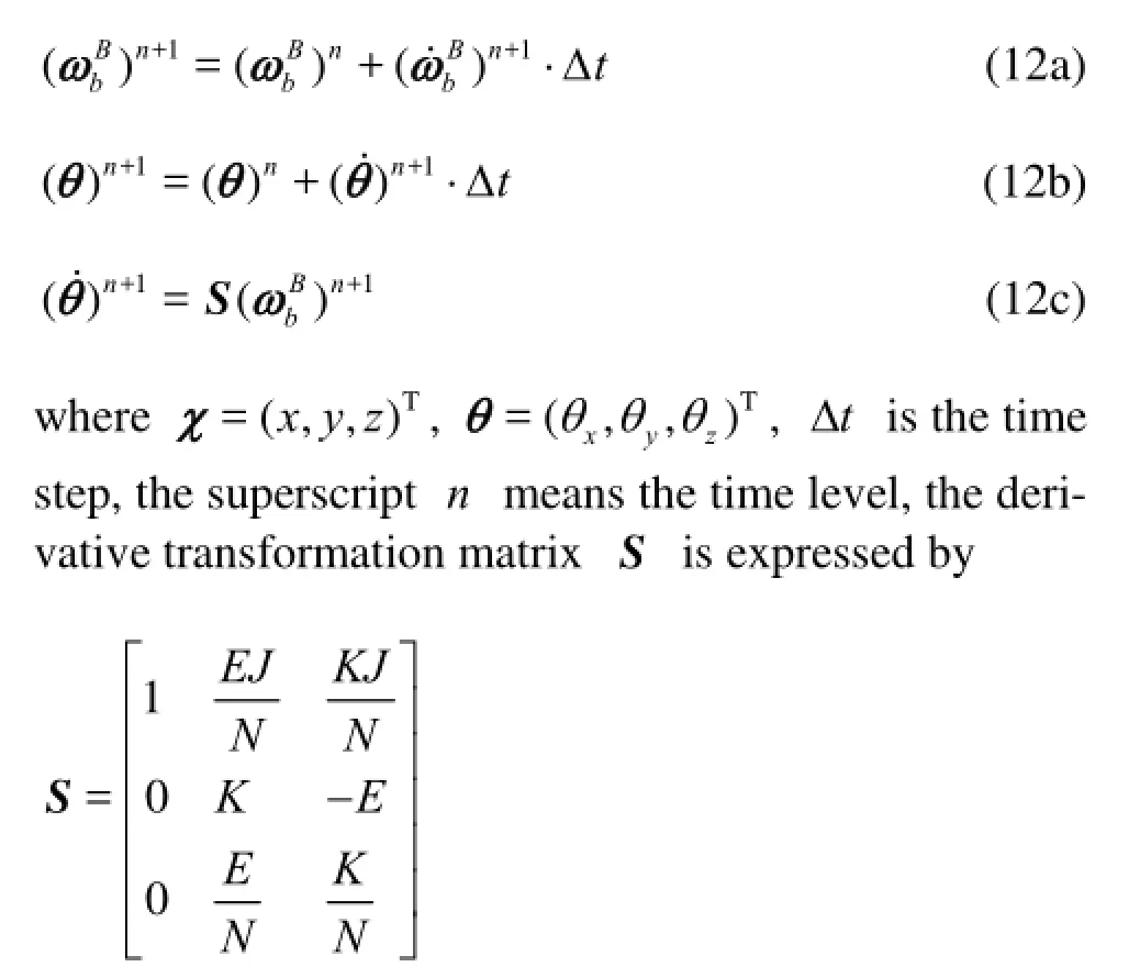
Introduction
When a high-speed weapon covered with natural and ventilated cavities moves under water, the flow features are important issues for the research and development. Because of some unavoidable objective factors in the process of trajectory controls, such as that of adjusting the deflection angle of the cavitator, there exist abnormal deviations in the cavity pattern, the hydrodynamics and the underwater trajectory in some phase of motion. These deviations can degrade the weapon’s combat performance. Thus, the prediction of the flow properties of the vehicle is very important.
For a submarine-launched missile model under the action of a fixed external thrust, Wang et al.[1]experimentally measured the thrust, the pressure overload and the structural strain of the model, and theoretically analyzed the underwater trajectory. Based on the theorems of the momentum and the moment of the momentum, Zhang et al.[2]built a mathematical model of the trajectory for a carrier with six degrees of freedom in the dynamic coordinate system. They proposed a control scheme of a rocket-assisted torpedo’s underwater trajectory using MATLAB/SIMULINK. Gu et al.[3]studied a problem of the underwater trajectory for a mine launched from a submarine in the phase of motion without external forces, and they put forward a theoretical model to analyze the underwater trajectory under the effect of the current in the simulation environment of MATLAB. An improved control and guidance system for supercavitating vehicles was designed. Cao et al.[4]established simplified equationsfor the longitudinal motion of supercavitating vehicles to simulate the trajectory of vehicles travelling at a speed of around 90 m/s. The calculating results show that the motion of a supercavitating vehicle at changeable depth and direction can be handled using typical control schemes of the top steer without a feedback system.
The previous simulations are mostly carried out in the framework of self-developed programs or other tools like MATLAB based on many hypotheses using several semi-experimental and semi-theoretical formulas. These studies point to a kind of study method, to obtain the laws of vehicles’ motion affected by single-factor or multi-factors in an ideal state. However, with the development of computer hardware and numerical techniques, it is possible to couple the solution of the flow field and the body’s motion. This kind of study method[5]is advantageous in analyzing the flow structures and the mechanisms of a complicated physical phenomenon.
1. Governing equations of the flow field
The vapor phase should also satisfy the continuity condition during the phase-transition process[8]
where ρ is the density, t stands for the time, u denotes the velocity vector, p is the pressure, the subscripts m, l and v, respectively, indicate the mixture, the liquid phase and the vapor phase.
The volume fractions of the phases satisfy
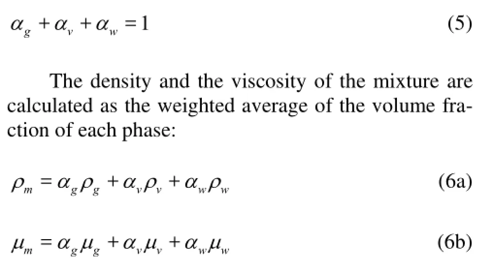
Additionally, two individual transport equations are employed to describe the phase-transition process between the vapor and the liquid.
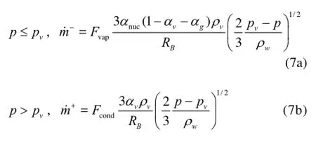
where RBis the radius of the vapor bubble, and a value of 10-6m is selected, αnucdenotes the volume fraction of the gas nuclei in the liquid, and here a value of 10-5is specified. In addition, Fvap=0.02, Fcond=0.001.
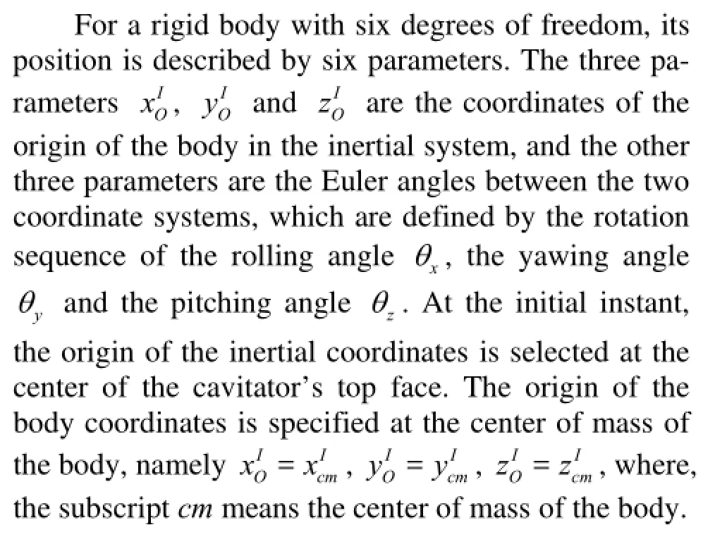
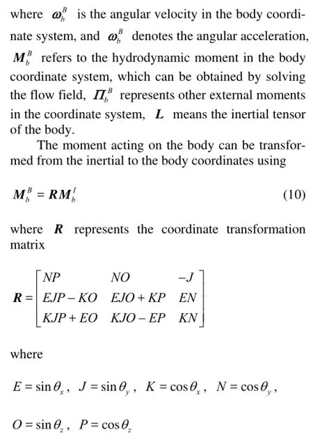
2. Equations of motion for the free rigid body
2.1Coordinate system
The coordinate systems with the right-hand rule are defined as in Fig.1. The superscripts I and B refer to the inertial system and the body system, respectively. The cavitator’s deflection angle αd(<90o) is determined by the anticlockwise angle from the axis of yBto the plane of the cavitator. The different lift force can be obtained by adjusting the deflection angle to change the body’s attitude motion.
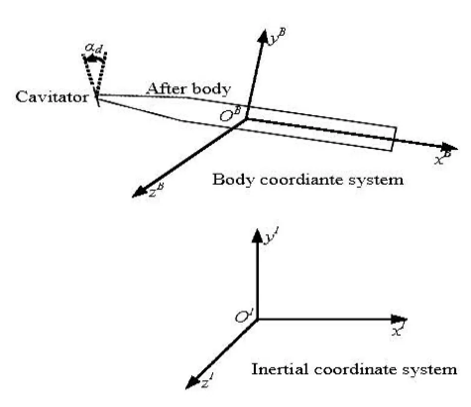
Fig.1 The coordinate systems, cavitator’s deflection angle
2.2Governing equations
In the inertial coordinate system, the body’s translational motion is governed by the equation

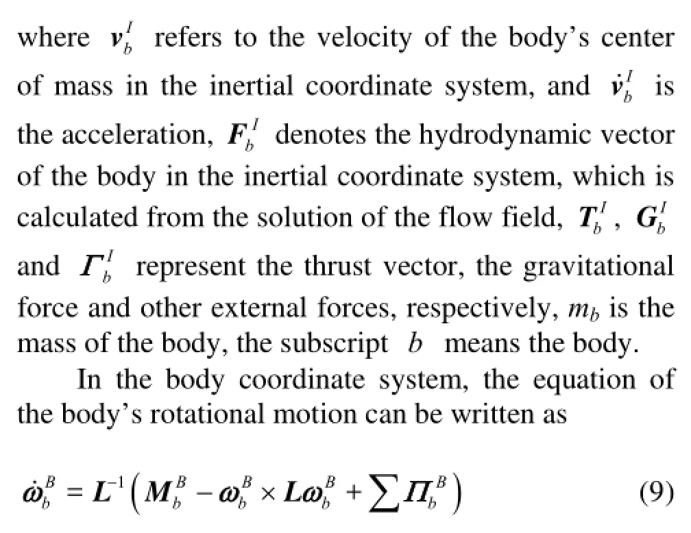
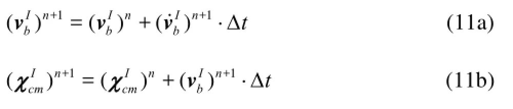
After the accelerations are computed from Eq.(8) and Eq.(9), the velocities, the coordinates of the body’s center of mass and the angular velocities, the Euler angles are derived by an explicit difference scheme.
2.3Dynamic mesh method
The dynamic mesh method can be used to model the flows where the shape of the domain changes with time due to the motion on the domain boundaries. The motion can be a prescribed motion or/and unprecribed motion where the sequence motion is determined based on the solution at the current time. The updating of the volume mesh is handled automatically at each time step on the basis of the new positions of the boundaries. At present, there are three kinds of dynamic mesh methods used widely: the fixed-grid method[15], the sliding mesh method[16]and the local remeshing method[17].
In the process of updating the volume mesh, the integral form of the conservation equation for a general scalar ζ on an arbitrary control volume V with a moving boundary can be expressed as
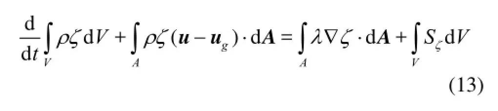
where ugis the mesh velocity of the moving mesh, λ is the diffusion coefficient, Sζis the source term of ζ, A is used to represent the boundary of the control volume V.
In the fixed-grid method adopted in this paper, the mesh in the computational domain moves with the motion of the body. In other words, the number of the grid and the relative positions between the grid nodes remain unchanged during the whole calculation.
3. Results and discussions
3.1Computational parameters
The vehicle’s total length and maximal diameter are denoted by L and D, respectively, and the components along the axial direction include a cavitator (head rudder), two bowl-shaped flow guides, an afterbody, a cross trailing rudder and a trailing cylinder. The cavitator is a disk with a diameter of Dn.
In the course of the simulation, the motion of the vehicle is confined entirely to the plane of the pitch. Thus, the flow is symmetrical with respect to the plane of zI=0, and there are just three degrees of freedom, namely (xI,yI,θz). The flow domain can be reduced by half to save the calculation time. A multi-block structured mesh is generated, containing a total number of about 1.5×10⁶cells.
The upstream boundary and the external boundary are disposed with a constant velocity. The downstream boundary is specified with a fixed static pressure. A fixed mass flux is set on the ventilating nozzle. The surface of the vehicle is under no-slip wall condition.
The deflection angle of the cross trailing rudder is selected as 0oand keeps constant. The initialized velocities are set to a value of vIbx0in x direction, and 0 in both y and z directions. A starting coordinates of (0.5L,0,0) are specified at the center of mass of the vehicle. Each component of the initialized angular velocity is given a value of 0 rad/s. The Euler angles of (0,0,θz0) are given in the startup solution.
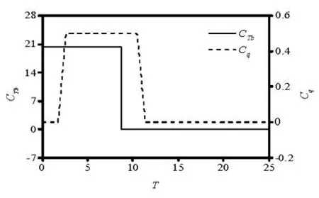
Fig.2 CTb, Cqvs. T
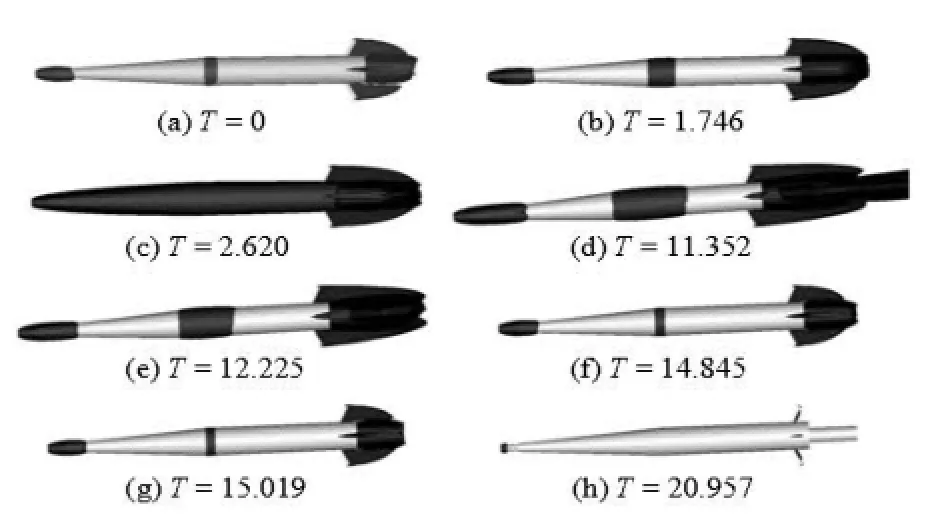
Fig.3 Shapes of cavity at different times, αd=0o
3.2Cavity pattern
Figure 3 illustrates the history of the shape of the cavity when αdis equal to 0o. It can be seen from Fig.3(a) and Fig.3(b) that before the gas ventilating, namely T<1.746, the vehicle is in the phase of the early acceleration accompanying the natural cavitation occurred at the head-body, near the shoulder and the end of the big cylinder and downstream from the cross trailing rudder.
Figure 4 presents the relationships between the cavitation number, the cavity length and the cavitator’s deflection angles at T=0 and T=1.746, where


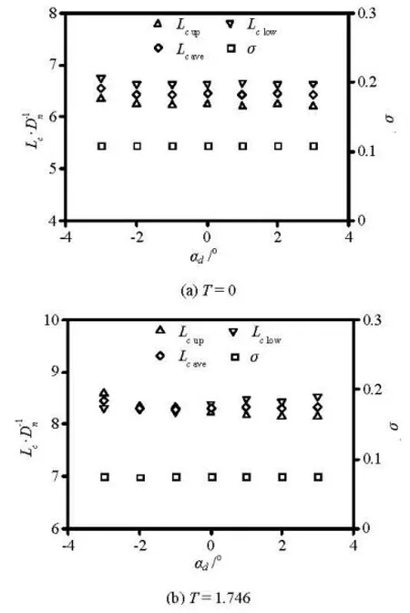
Fig.4 Relations of σ,cL withdα at different times
During the time T in the range of 1.746-12.225, the vehicle is in the phase of the acceleration and the ventilated cavitation. It is found from Fig.3(c) that, within the non-dimensional time of 0.837 after ventilating the gas, a supercavity is formed rapidly, and a natural cavity with a length of 1/3L-2/5L appears downstream from the cross trailing rudder. During the phase of the ventilated cavitation, the difference in the vehicle’s motion attitude between the cavitator’s deflection angles becomes gradually notable because of the variation of the lift.
When T is equal to 11.352, the gas supply is stopped. After a time measured by the non-dimensional time of about 0.837, namely, T>12.225, the vehicle resumes to a state of natural cavitation again as shown in Fig.3(e). Meanwhile, the vehicle is already released from the external thrust at T=8.732. Therefore, the vehicle is in the phase of the deceleration, and the cavity length is reduced gradually as illustrated in Fig.3(h).
3.3Hydrodynamics

Fig.5 Relation ofdC with time

Fig.6 Relation of Cpwith time, αd=0o
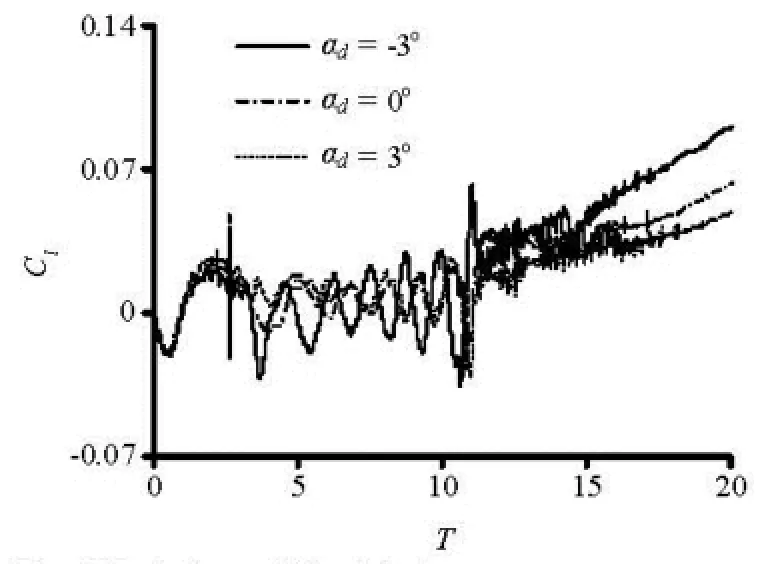
Fig.7 Relation oflC with time
It can be seen from Fig.5 that, during the phase of the acceleration, the drag coefficient goes down at first quickly and then slowly. After stopping the gas supply, the drag coefficient increases significantly. It should be noticed that, there are two distinctly sudden changes in the drag coefficient. The first sudden change results from the action of the ventilating gas. The second sudden change is caused by the transition from the cavitation to the non-cavitation on the trailing cylinder.
Taking αd=0ofor example, Fig.6 shows the variation of the pressure coefficient with time monitored at the point A, which is 0.8 radius away from the center of the trailing cylinder’s bottom face. Figure 3(f) demonstrates that the trailing cylinder is covered with the natural cavity at T<14.845. So, the pressure on the bottom of the trailing cylinder approaches the saturated pressure of the liquid to raise the bottom drag coefficient of the vehicle. As T is equal to 15.019, the bottom face of the trailing cylinder is in the vicinity of the natural cavity’s closure region due to the decreasing velocity of the vehicle and the increasing natural cavitation number, as shown in the Fig.3(g). Under the influence of the high pressure in the cavity’s closure region, the pressure on the bottom face goes up suddenly to have an evidently lower bottom drag coefficient than before. Then, because of the further decrease of the vehicle’s velocity, the size of the natural cavity reduces gradually, which weakens the influence of the high pressure in the closure region on the bottom of the trailing cylinder with the result of the enlarged bottom drag coefficient. In addition, at a same time, after stopping the gas supply, the greater the deflection angle of the cavitator is, the smaller the drag coefficient is.
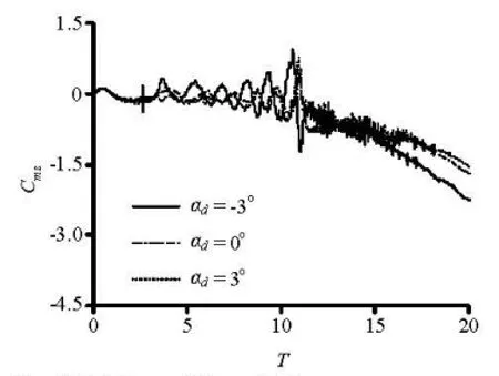
Fig.8 Relation of Cmzwith time
It can be seen from Fig.7 that the lift coefficient curve has an upward tendency as a whole. During the artificial ventilation, one sees propagations of the disturbance caused by the supercavity’s formation and disappearance, and the sharp variation in the wet area of the vehicle. Under these conditions, the lift coefficient assumes a wavy curve, as well as the pitching moment, the linear velocity in y direction, and the angular velocity about z axis. Moreover, the greater thecavitator’s deflection angle, the smaller the lift coefficient is. After the gas supply is stopped, the magnitude of the wavy curve drops step by step. At a same time, the larger the cavitator’s deflection angle is, the less the lift coefficient becomes.
Figure 8 shows that the lift has a strong influence on the pitching moment. Both of them vary in a manner opposite to each other.
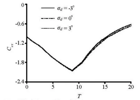
Fig.9 Relation of Cvxwith time
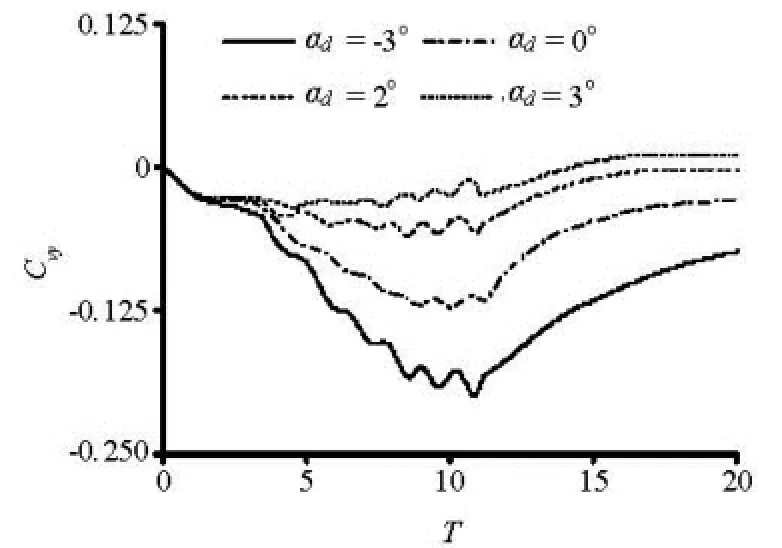
Fig.10 Relation of Cvywith time
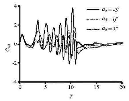
Fig.11 Relation ofzCωwith time
3.4Underwater trajectory

Fig.12 Distribution of the center of mass, T=20.957
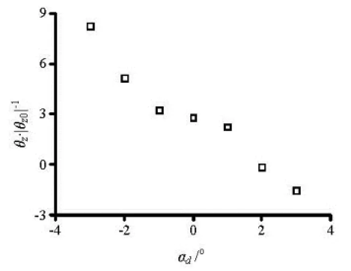
Fig.13 Distribution of θ2, T=20.957
Figures 12-13 show the distributions of the center of mass and the pitching angle of the vehicle in the computational range of the cavitator’s deflection angle at T=20.957. It is found from these scattered points that the pitching angle turns from positive to negative with the increase of αd, and the navigation distance becomes greater, whereas the navigation depth becomes smaller. When the deflection angle lies in the small range of -1o-1o, the position of the center of mass and the pitching angle of the vehicle are more close to each other. However, when the deflection angle are less than -1oor greater than 1o, the position of the center of mass and the pitching angle change significantly.
4. Conclusions
In the present work, a method of numerical simulation is put forward to calculate the free moving phase of an underwater supercavitated vehicle under the action of an external thrust. The influences of the cavitator’s deflection angle ranging from-3oto 3oon the cavity pattern, the hydrodynamicsand the underwater trajectory are investigated. Based on computational results, several conclusions can be qualitatively drawn by analysis as follows:
(1) According to the segmental law of the gas supply, the cavity pattern can be divided into three phases in order, namely, the natural cavitation, the ventilated cavitation and the natural cavitation. The deflection angle has very little impact on the cavity pattern.
(2) The relation of the drag coefficient versus time is very complicated with some sudden changes under the action of a thrust and under ventilation conditions. On the whole, the lift coefficient goes up while the pitching moment coefficientgoes down, along with oscillations in the phase of the ventilated cavitation. When the deflection angle increases, the variation curves of the lift and the pitching moment coefficient become flatter. In the phase of the second natural cavitation, at a same time, the greater the deflection angle is, the lower the drag and the lift coefficients are, whereas the higher the pitching moment coefficient is.
(3) The effect of the external thrust makes the horizontal linear velocity accelerate at first, and then decelerate. Furthermore, the vertical linear velocity changes in a wave shape. At a given moment, the greater the deflection angle, the larger the vertical linear velocity is. With the growing deflection angle, the variation curves of the vertical linear velocity and the pitching angle velocity become flatter, along with oscillations in the phase of the ventilated cavitation. With a certain deflection angle of the cavitator, the underwater vehicle can navigate in a pseudo-fixed depth.
(4) At the finishing time of the free moving phase, with an increase in the deflection angle, the navigation distance of the vehicle increases, but the depth decreases. In addition, the pitching angle varies from positive to negative. As the deflection angle lies in the small range of -1o-1o, the position of the center of mass and the pitching angle of the vehicle are close to each other. However, when the deflection angle are less than -1oor greater than 1o, the position of the center of mass and the pitching angle change significantly.
[1] WANG Cong, WANG Xue-xiao and XU Shi-chang et al. Analysis and testing on dynamic property of submarine-launched missile[J]. Missiles and Space Vehicles, 2002, 2: 12-15(in Chinese).
[2] ZHANG Xue-feng, PAN Guang and WANG Peng. Underwater trajectory design of rocket assisted torpedo[J]. Torpedo Technology, 2007, 15(4): 11-14(in Chinese).
[3] GU Chuang, PANG Hong-zhao and ZHANG Yong. Research of sea water that affect the trajectory of mine projected by submarine[J]. Ship Electronic Engineering, 2010, 30(2): 168-171(in Chinese).
[4] CAO Wei, WEI Ying-jie and HAN Wan-jin et al. Simulating the trajectory of supercavitating vehicles[J]. Journal of Harbin Engineering University, 2010, 31(3): 323-328(in Chinese).
[5] YANG Xiao-guang, CHEN Huan-long and LIU Huaping et al. Simulation about 3D flow field of missile underwater motion and water-exit process[J]. Journal of Ballistics, 2010, 22(1): 107-110(in Chinese).
[6] MANNINEN M., TAIVASSALO V. and KALLIO S. On the mixture model for multiphase flow[M]. Espoo, Finland: VTT Publications, 1996.
[7] HUANG Biao, WANG Guo-yu and ZHAO Yu. Numerical simulation unsteady cloud cavitating flow with a filter-based density correction model[J]. Journal of Hydrodynamics, 2014, 26(1): 26-36.
[8] ZWART P. J., GERBER A. G. and BELAMRI T. A two-phase flow model for predicting cavitation dynamics[C]. Fifth International Conference on Multiphase Flow. Yokohama, Japan, 2004.
[9] SPALART P., ALLMARAS A. A one-equation turbulence model for aerodynamic flows[R]. Technical Report AIAA-92-0439, American Institute of Aeronautics and Astronautics, 1992.
[10] HUA Zu-lin, XING Ling-hang and GU Li. Application of a modified quick scheme to depth-averaged -kε turbulence model based on unstructured grids[J]. Journal of Hydrodynamics, 2008, 20(4): 514-523.
[11] YANG Guo-gang, DING Xin-wei and BI Ming-shu et al. Improved SIMPLE algorithm used in numerical simulation of flammable gas cloud deflagration[J]. Journal of Dalian University of Technology, 2004, 44(6): 789-792(in Chinese).
[12] CHENG Guang-hui, HUANG Ting-zhu and CHENG Xiao-yu. Preconditioned Gauss-Seidel type iterative method for solving linear systems[J]. Applied Mathematics and Mechanics (English Edition), 2006, 27(9): 1275-1279.
[13] CHEN Xin, LU Chuan-jing and LI Jie et al. The wall effect on ventilated cavitating flows in closed cavitation tunnels[J]. Journal of Hydrodynamics, 2008, 20(5): 561-566.
[14] HU Yong, CHEN Xin and LU Chuan-jing et al. Study on the interaction between ventilated cavitating flow and the exhausted gas of an underwater vehicle[J]. Chinese Journal of Hydrodynamics, 2008, 23(4): 438-445(in Chinese).
[15] AZCUETA R. Computation of turbulent free-surface flows around ships and floating bodies[J]. Ship Technology Research, 2002, 49: 999-1022.
[16] BASARA B., ALAJBEGOVIC A. and BEADER D. Simulation of single- and two-phase flows on sliding unstructured meshes using finite volume method[J]. International Journal for numerical methods in fluids, 2004, 45(10): 1137-1159.
[17] CHIANG C. H., JONG B. S. and LIN T. W. A robust feature-preserving semi-regular remeshing method for triangular meshes[J]. Visual Computer, 2011, 27(9): 811-825.
10.1016/S1001-6058(14)60078-0
* Project supported by the National Natural Science Foundation of China (Grant Nos. 11372185, 11102110) and the Shanghai Leading Academic Discipline Project (Grant No. B206).
Biography: CHEN Xin (1976-), Male, Ph. D.,
Associate Professor
猜你喜欢
杂志排行

水动力学研究与进展 B辑的其它文章
- Stability of fluid flow in a Brinkman porous medium-A numerical study*
- Multi-point design optimization of hydrofoil for marine current turbine*
- An iterative Rankine boundary element method for wave diffraction of a ship with forward speed*
- Sediment rarefaction resuspension and contaminant release under tidal currents*
- Vadose-zone moisture dynamics under radiation boundary conditions during a drying process*
- Experimental and numerical study on hydrodynamics of riparian vegetation*