Relativistic effect on synergy of electron cyclotron and lower hybrid waves on EAST
2022-01-10LonghaoMA马龙豪NongXIANG项农YuehengHUANG黄跃恒YeminHU胡业民andXuemeiZHAI翟雪梅
Longhao MA(马龙豪) ,Nong XIANG(项农),Yueheng HUANG(黄跃恒),Yemin HU (胡业民)and Xuemei ZHAI (翟雪梅)
1Institute of Plasma Physics, Chinese Academy of Sciences, Hefei 230031, Peopleʼs Republic of China
2 University of Science and Technology of China, Hefei 230026, Peopleʼs Republic of China
3 Advanced Energy Research Center,Shenzhen University,Shenzhen 518060,Peopleʼs Republic of China
4 Key Laboratory of Optoelectronic Devices and Systems of Ministry of Education and Guangdong Province, College of Optoelectronic Engineering, Shenzhen University, Shenzhen 518060, Peopleʼs Republic of China
Abstract In recent experiments on EAST, the electron temperature at the center can be raised to 9.7 keV by injecting electron cyclotron (EC) and lower hybrid (LH) waves simultaneously.With such strong core electron heating,the relativistic effect could play an important role in the interactions between the plasma and waves.In order to explore the relativistic effect on synergy between the EC and LH waves on EAST, ray-tracing/Fokker–Planck simulations are conducted to investigate electron heating for a typical discharge with a center electron temperature of 9.7 keV.It is found that the relativistic effect can cause the EC wave to deposit its power deeper in the plasma core, where the synergy between the EC and LH waves occurs and enhances the absorption of the LH waves.As a result, a high center electron temperature can be achieved.
Keywords: electron cyclotron waves, lower hybrid waves, synergy effect, relativistic effect
1.Introduction
The Experimental Advanced Superconducting Tokamak(EAST) is a fully superconducting tokamak device with advanced divertor configuration and International Thermonuclear Experimental Reactor (ITER)-like scheme heating [1].The heating and current drive(CD)on EAST is mainly provided by radiofrequency(RF)waves,among which electron cyclotron(EC)and lower hybrid(LH)waves are important.In the past few years,experimental campaigns have achieved steady-state longpulse plasmas with pure RF heating on EAST [2–4].The development of a special scenario with a high center electron temperature was one of the main goals of EAST in experimental activities in 2018 and 2019.In recent experiments, the center electron temperature has reached 9.7 keV through the launch of both EC (140 GHz) and two LH (4.6 GHz and 2.45 GHz)waves.This temperature cannot be achieved,however,if the EC and LH waves are launched separately with the same input power.Therefore, the enhanced electron temperature might be caused by the synergy of the EC and LH waves.
In the early 1980s, Fidone first proposed that the total CD injected with EC and LH waves simultaneously was greater than the sum of the CD by the two waves injected separately, and then synergy of two waves happened.Henceforth, targeted verification experiments have been carried out on many devices,such as WT-2 [5, 6], JFT-2M [7, 8] and WT-3 [9, 10].These experiments suggested that the EC waves could be interacting with the suprathermal electron tail driven by the LH waves and provide an obvious current ramp-up.However, none of the works mentioned above analyzed the synergy effect both qualitatively and quantitatively.In 2004, a qualitative and quantitative assessment of the synergy effect was performed by Giruzziet alin an experiment on Tore Supra, in which the synergy made the efficiency of ECCD of the same order of magnitude as that of LHCD [11].Giruzzi found that the electrons accelerated by the EC waves could be scattered into the resonance region of the LH waves and further accelerated by the LH waves.As a result, electrons resonating with LH waves carried a higher perpendicular velocity,from which the synergy effect originated.The analytical calculations of the synergy effect of two waves were investigated.According to the condition of the synergy effect,the quasi-linear domains of the two waves have to be within or close to each other[12],and it was found that the synergy effect between EC and LH waves depended on the resonance positions of the two waves and the power of the EC waves (with the LH wave power fixed) [13].On EAST a further effect exists due to the coupling of LH waves at 4.6 GHz and 2.45 GHz [14].
However, the relativistic effect has seldom been mentioned in previous works because of the low electron temperature, and it has not been investigated at comparable electron temperatures.It can be expected that if the electron temperature is high enough,the relativistic effect will become significant and will have an impact on the power deposition of the RF waves,which is consistent with the fact that there will be such strong core heating.
The ray-tracing/Fokker–Planck simulation results in our work show that the resonance layer of the EC wave will move from the low-field side to the near axis with the relativistic effect.The same simulation results with and without the relativistic effect were also found for other devices[15,16].Meanwhile,the position of the synergy effect between EC and LH waves was shifted due to the relativistic EC power deposition,which in turn affected the LH power deposition.The synergy effect between EC and LH waves near the axis was also found to enhance the power deposition of LH waves, maintaining the high temperature in the core.Consequently, we must pay attention to the relativistic effect when simulating the power absorption of RF waves at high temperatures.The main objective of this paper is to research the effects of relativity on the energy absorption at high temperatures in the presence of two-wave synergy.
The paper is arranged as follows:the physical mode land simulation setup is given in section 2; the simulation results and the corresponding physical pictures are shown in section 3; and a summary is given in section 4.
2.Physical model and simulation setup
The experiment (plasma current 0.5 MA) was carried out by injecting the two different frequencies of LH waves(f0=4.6 GHz and 2.45 GHz) and the EC wave (f0=140 GHz) in a discharge with the central line-averaged density (ne=2.0×10¹⁹m−3) and the vacuum magnetic fieldBT0=2.4 T (at the magnetic axis).The time traces of the plasma parameters(shot#90 466)are shown in figure 1.The equilibrium att=8.117 s was reconstructed by kinetic EFIT with constraints from Faraday angles measured by a polarimeter–interferometer (POINT) diagnostic [17].The peak parallel refraction indexes of the main lobe spectra for the 4.6GHz LH wave were 2.26 and −5.855, and the initial spectral width was 0.3.The 2.45 GHz LH wave was launched with the power spectral peaks at the parallel refraction indexes 2.1 and −7.3, and the initial spectral width was 0.5.The toroidal launch angle of the ECRH system(port M)was fixed at α=200° with a frequency of 140 GHz (X2-mode).
The temperature profiles are measured from Thomson scattering (TS) diagnostics because the ECE measurement is unavailable for this shot.Currently, there are 40 measurement points on the way along the laser beam which cover the radial range of 0–0.95aon EAST, whereais the minor radius.The principle of the TS diagnostic is that,when the laser pulse passes through an incoherent plasma,an accelerating electron generates a radiative electric field.As a result,the scattered spectra of the scattered waves can be measured and the scattered spectra are related to electron temperature.The relativistic effect on TS measurement has been discussed [18], and the scattered spectrum for the high temperature (Te<10 keV) becomes

where θ is the angle between the observation direction and the laser incidence direction, λ0is the wavelength of the incident wave, Δλ is the difference between the wavelength of the scattered wave and that of the incident wave,kis Boltzmann constant,Teis the electron temperature,cis the speed of light in a vacuum, andmeis the resting electron mass.The relativistic corrections have been included in the TS measurement of the electron temperature on EAST.
In this work, the ray-tracing codes GENRAY [19] and TORAY-GA[20]are used to obtain the wave electric field of the LH and EC waves along the ray trajectory, respectively.The ray tracing with the relativistic correction significantly reduces the computational speed.The effects of the relativistic effect on the wave ray tracing have been estimated and can be ignored.The ray-tracing codes and the quasi-linear Fokker–Planck code CQL3D [21] are combined to reconstruct the quasi-linear diffusion coefficient.The CQL3D code is used to calculate the evolved electron distribution functionfwith the quasi-linear diffusion coefficient and thefdistorted by the EC and LH waves is described as [22]:

where (∂f∂t)cis the relativistic collision term [23],u=p/m=γvis the particle momentum per rest mass, andis the relativistic factor.DECand DLHare the EC and LH wave quasi-linear diffusion tensors which can be obtained from the relativistic local expressions, respectively [24, 25]:

where

and

where ω is the wave frequency, andk‖(k⊥) is the parallel(perpendicular) component of the wave vector k (parallel and perpendicular directions are defined in terms of the equilibrium magnetic field).The argument of the Bessel functions isu‖(u⊥)is the parallel(perpendicular)component of u,andis the unit vector in theu‖(u⊥) direction.nis the order of cyclotron interaction,the zeroth harmonic(n=0)is for the LH waves andn=2 for the EC waves on EAST.is the local cyclotron frequency with charge.Ex,Ey, andE‖are the components of the wave electric field.It can be seen that the influence of the relativistic effect has been included in D.According to equation (2), the steady-state electron distribution function is determined by the interaction of the EC and LH waves.The cooperation could be stronger when the resonance regions of the EC and LH waves overlap.Equation(2)is solved by CQL3D code combined with the wave electric field along the ray trajectory obtained by GENRAY/TORAY-GA.
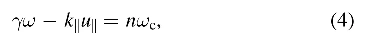
The resonance condition for an electron interacting with the EC and LH waves is
and the non-relativistic limit is obtained when taking γ=1.
The resonance curve in the momentum space for LH waves, according to equation (4) withn=0, is a hyperbola determined by

whereute=γvteandvte=Te/meis the electron thermal velocity, andmeis the electron rest mass.Similarly, the resonance condition for the EC waves is an ellipse in momentum space,

where

3.Simulation results
3.1.Influence of relativistic effect on RF wave power deposition
In this section, we will show the influence of the relativistic effect on RF waves alone,which can aid understanding of the influence of the relativistic effect on the synergy effect between EC and LH waves.
3.1.1.EC wave.Figure 2 displays the diagram of the cyclotron resonance layer with and without the relativistic effect in the poloidal cross-section (equation (4)) for shot #90 466 on EAST.Clear differences can be seen that are caused by the relativistic effect, and such differences are in the poloidal cross-section where the resonance layer is moved to the black dashed line from the blue dashed line.

Figure 1.Time traces of the EAST discharge parameters (shot # 90 466).(a) Plasma current (Ip), (b) central line-averaged electron density(ne), (c) loop voltage (Vloop), (d) power of the 4.6 GHz and 2.45 GHz LH waves, (e) power of the EC wave, and (f) and (g) electron temperature and density profiles at t=8.117 s, respectively.
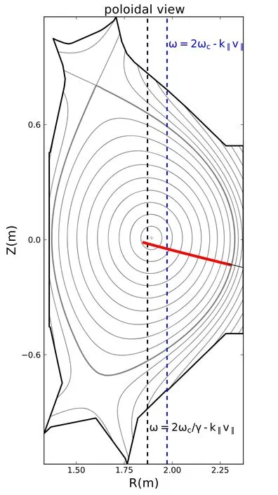
Figure 2.Diagram of a ray trajectory of the EC wave (solid red) in the poloidal cross-section.The resonance layers in the relativistic and non-relativistic cases are indicated by the black dashed and blue dashed lines, respectively (v‖=v⊥=vte and N‖=0.5).
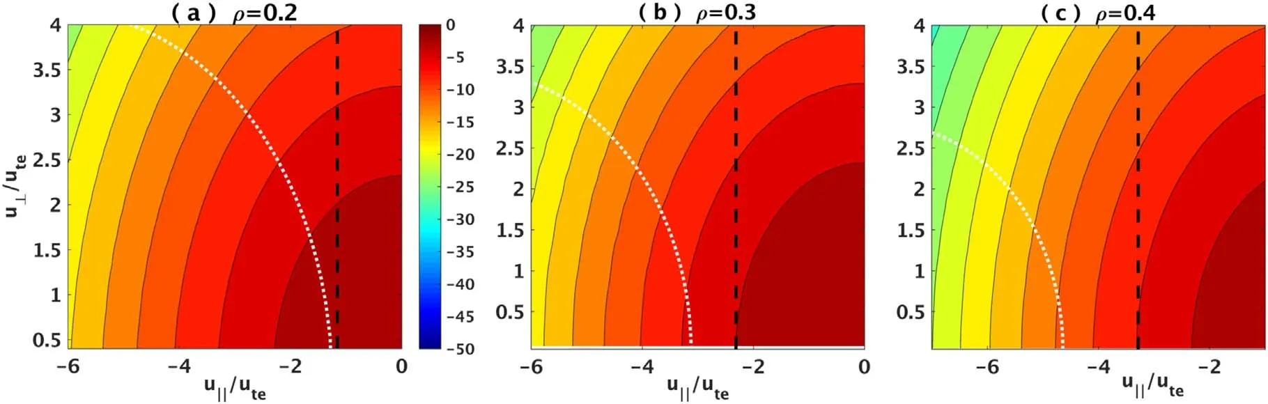
Figure 3.Contour plots of log(f)for different radial locations.The resonance curves for the non-relativistic and relativistic cases in the phase space are denoted by the black dashed and white dotted lines,respectively.The bending of the resonance curve comes from the inclusion of the relativistic effect in the resonance condition.
Figure 4.Power deposition profiles of the EC wave: the relativistic case (black solid line) is on-axis and the non-relativistic case (red dashed line) is off-axis.

Figure 5.Power deposition profiles of the 4.6 GHz wave alone with the relativistic effect(black solid line)and non-relativistic effect(red dashed line).
Contour plots of log(f) (using the relativistic Maxwellian and normalized by their maximum values) at different flux surfaces ρ and the corresponding resonance curves(equation(6))in momentum space are shown in figure 3, where ρ is the normalized square root of the toroidal magnetic flux.For a given magnetic flux surface, the number of resonance electrons is decreased due to the relativistic effect, since the resonance condition in equation (6) is modified now considering the relativistic effect.From figure 3(c), we see that the relativistic effect will be significant in spite of the low temperature and the resonant electrons are few in number.Since this is quite far in the distribution,there are few such electrons and the damping is weak.Considering the relativistic effect, the resonance curve bends and moves away from the center of the distribution function, while the number of resonant electrons decreases accordingly.It is known that the damping rate of the extraordinary mode(X-mode)is approximated by the expression[16,26]γeX∝exp[−u‖22(Teme)],so the closer to the center of the distribution function with the smaller Abs(u‖) (u⊥has been integrated), the more electrons there are, which means that the damping is stronger and the energy is absorbed more quickly.It can be predicted that the position where the power is completely absorbed is relatively outward in the nonrelativistic case.
The power deposition profiles of a single EC wave with(black solid) and without (red dashed) relativistic effects are shown in figure 4, in which the peak value of the power deposition profile is located at the magnetic flux surface ρ ∼0.25 for the non-relativistic case and ρ ∼0.06 for the relativistic case.We already know that the non-relativistic damping is stronger for the EC wave.Therefore,the energy of the EC wave in the non-relativistic case will be absorbed faster in the incident process, which coincides with what we expected above and the observations in the previous literature [15, 27].
3.1.2.LH wave.The Landau damping rate can be obtained by previous models[28,29]and the imaginary part of theN⊥(ImN⊥) is rewritten as

where∊Re is the real parts of the cold electrostatic dispersion relation of Stix [30] evaluated in the limitωci2≪and ∊iis the imaginary parts of the dispersion relation.Furthermore,the damping rate is rewritten as

It is obtained that the damping rate is approximately proportional toFor a relativistic Maxwellian distribution,
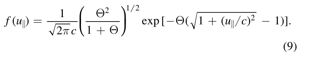
Heref(u‖) is the normalized function ofu‖only, where the perpendicular velocity is variable with an effective velocity spread of(Teme)12.Hence,

where

We compare the power deposition profiles of the LH waves with and without the relativistic effect, taking the 4.6 GHz LH wave as an example,which is shown in figure 5.The relativistic result is denoted by the black solid line and the non-relativistic result is denoted by the red dashed line.It is observed that the two power deposition profiles are close to each other in the range of 0<ρ<0.5, compared with the relatively strong shift of power deposition within 0.6<ρ<0.8.Based on the simulation, it is indicated that the rays nearN‖=2.5 andN‖=−7 are responsible for the power deposition in the ranges of 0<ρ<0.5 and 0.6<ρ<0.8, respectively.According to equation (10), we obtainwhere⊥NImRand⊥NImNRrepresent the relativistic and nonrelativisticN⊥Im ,respectively.It also explains why there is a bigger difference between the relativistic and non-relativistic cases at 0.6<ρ<0.8.In conclusion, the effect of relativity on the linear damping rate of the LH wave components with highN‖is more significant than that with lowerN‖.
3.2.Influence of relativistic effect on total power deposition
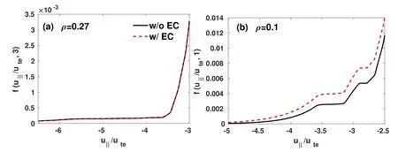
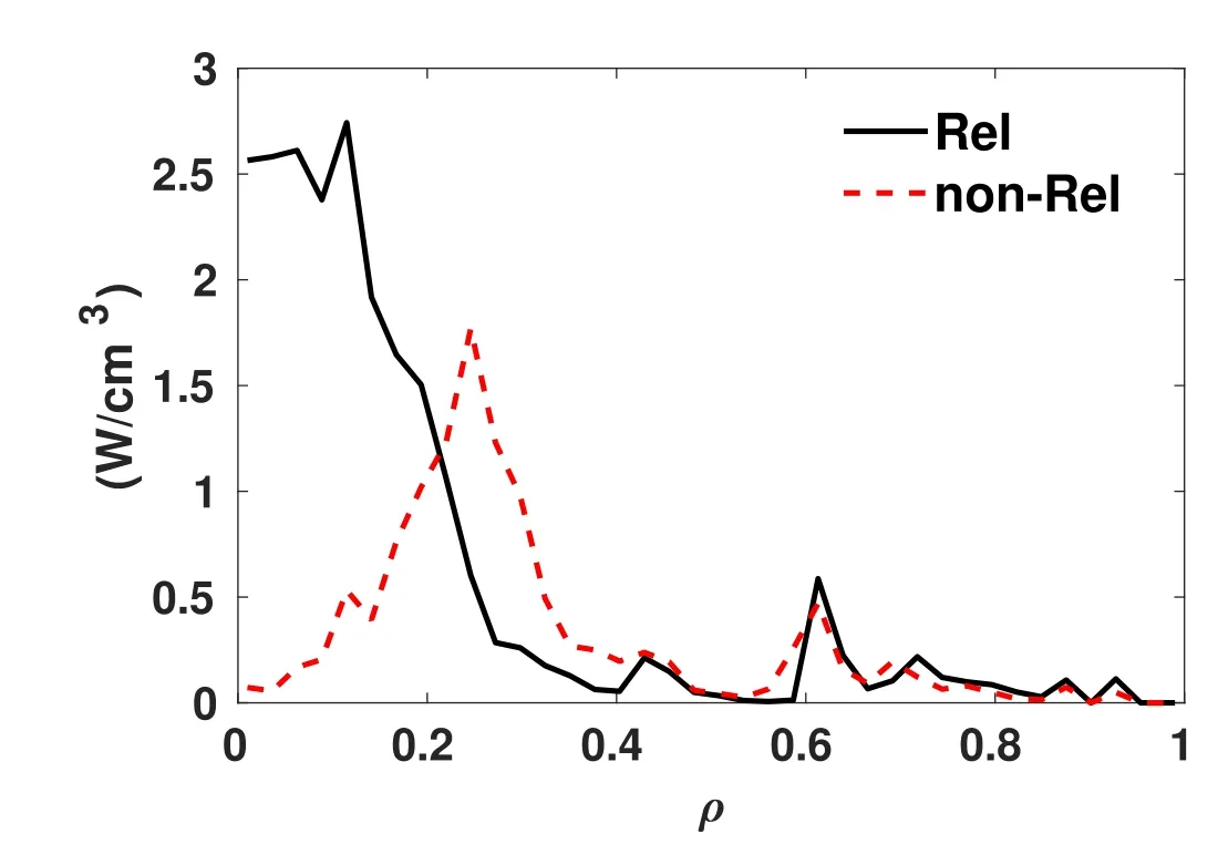
In the previous section, the relativistic effect on the power absorption of the individual EC and LH waves is discussed.In this section the electron simultaneously interacts with EC and LH waves, and the influence of the relativistic effect is investigated.The power deposition profiles of the LH waves(2.45 GHz and 4.6 GHz)with and without the EC wave in the non-relativistic cases are shown in figure 6.We can see that the LH wave power deposition in the region of 0.2<ρ<0.3 is faintly enhanced by the EC wave and the enhanced region is the power deposition region of the EC wave(see figure 4),which indicates that the synergy might occur between the EC and LH waves.Figure 7 displays the contour of the nonthermal electron distribution function at ρ=0.27 for the cases of figure 6.Figure 7(a) shows the contour of the nonthermal LH-drive electron distribution function, and the quasi-linear plateau corresponds to the velocity space range of approximately −6.5 Figure 6.Non-relativistic power deposition profiles of the two LH waves.The black solid line represents the result without the EC wave in simulation, while the red dashed line represents the case including the EC wave in simulation. Figure 7.Contour of the nonthermal electron distribution function fe in 2D velocity space and the corresponding resonance regions for the LH waves (blue dashed lines) and the EC wave (red dashed line) at ρ=0.27.(a) Without and (b) with the EC wave. Figure 8.Parallel velocity electron distribution functions versus the parallel velocity normalized by the local thermal velocity at v⊥/vte=3 in figure 7.The black solid and red dashed lines denote the f(v‖) of the cases without and with the EC wave, respectively. Here the value is taken atv⊥/vte=3 from figure 7,which is presented in figure 8.It can be clearly seen that the resonance plateau of the LH waves is lifted after joining the EC wave, indicating that more electrons resonate with the LH waves.The synergy effect happens and enhances the LH wave power deposition. As shown above,in the power deposition region of the EC wave,synergy between the EC and LH waves occurs.When the relativistic effect is taken into account the EC resonance is moved from ρ ∼0.3 to the near-axis region as indicated in figure 4.Hence it can be expected that the synergy might happen in the near-axis region with the relativistic effect.The influence of the relativistic effect on the LH power deposition during the simultaneous EC and LH wave injection is obtained by comparing figure 6 with figure 9.It can be found that the change of the position where LH waves power deposition is enhanced,which is consistent with the change of EC wave deposition.This agreement further confirms the conclusion that the synergy effect of the LH waves and EC wave is responsible for the enhancement of the LH power deposition.Additionally, based on the premise of the two LH waves coupling, the interaction between the EC waves and a sole frequency of LH waves is also analyzed.Figure 10 shows the simulated relativistic power deposition profiles of LH waves without and with the EC wave.As shown in figure 10(a),the injection of the EC wave leads to a pronounced modification of power deposition of the 4.6 GHz LH wave.In contrast, only very weak modification is observed on the power deposition profile of the 2.45 GHz LH wave as shown in figure 10(b).We also found that coupling the 4.6 GHz LH wave with the low-power 2.45 GHz LH wave resulted in a weak change in the power deposition profile of the 4.6 GHz LH wave, but a large change in the power deposition profile of the 2.45 GHz LH wave.Since the synergy effect between the 2.45 GHz and 4.6 GHz LH waves in our simulations coincides with that in[14],no extra effort is made to clarify the point here. To demonstrate the change of the location where the synergy effect occurs, we plot the nonthermal electron distribution function in figure 11 for two LH waves and a combination of EC and LH waves.Figures 11(a)and(c)show the electron distribution function at ρ=0.27.One can see that the modification of the electron distribution function is weak after the addition of the EC wave.Figures 11(b)and(d)show the electron distribution function at ρ=0.1.It is clear that the resonant electrons interacting with the LH waves have higher perpendicular velocity.As mentioned earlier, the change of the number of resonance electrons can be clearly shown by the change of the normalized parallel distribution function in figure 12.Comparing figures 12(a) and (b), we can see that the synergy effect appears at ρ=0.1, but disappears at ρ=0.27.The situation at ρ=0.2 is similar to that at ρ=0.1. Figure 10.Relativistic power deposition LH waves for(a)2.45 GHz and(b)4.6 GHz.The black solid lines and the red dashed lines represent the simulation results without and with the EC wave, respectively.It should be noted that the simulations are based on two kinds of parameters: the 2.45 GHz wave coupling with the 4.6 GHz wave, and the two waves coupling with the EC wave. Figure 11.Contour plots of the electron distribution function of the momentum space when the relativistic effect is taken into account.(a)and(b)Without the EC wave,(c)and(d)with the EC wave.Corresponding resonance regions for the LH waves(blue dashed lines)and the EC wave (red dashed lines). The total power deposition profiles are shown in figure 13.The power ratio between EC and LH is about 1:3 for the synergy cases from experimental data.The reason why figure 13 is similar to figure 4 is that the power deposition of the EC wave dominates near the core.It can be concluded that the total power is mainly deposited in the near-axis region with the relativistic effect, which is in agreement with the experimental observations.The interpretation of the above results is as follows.Firstly, the power deposition of the EC wave moves to the near axis for the case with the relativistic effect.Secondly, the LH power depositions near ρ=0.1 and ρ=0.2 are enhanced due to the synergy effect, which could result in an increase in wave power deposition near the axis.In fact,we also found the power deposition of the EC wave is enhanced due to the synergy effect.However, the enhancement is weak,because the power deposition of the EC wave is highly localized.The above investigation of the relativistic effect suggests that more wave power will be deposited in the core region due to the relativistic effect, thus achieving and maintaining a high electron temperature.Positive feedback loops in RF deposition using ECH-driven thermal perturbation have been studied [31].The confinement during ECH heating is investigated, and it is shown that the EC wave injection gives rise to a rapid rise in core electron temperature,and a slow increase in core electron temperature is caused by improved confinement due to the changes of the electron temperature and density profiles [32]. From the above simulation results, we have shown that the peak of the power deposition profile is closer to the axis when considering the relativistic effect.Therefore, it can be predicted that the current density profile is more peaked near the axis than that of the non-relativistic case.The simulation using Fokker–Plank code CQL3D and the transport code ONETWO [33] is performed to obtain the plasma current density profile.Figure 14 shows a comparison of the simulation results with and without the relativistic effect with the plasma current density profile reconstructed by POINT measurement.It can be obtained that the current density profile has a higher peak value with the relativistic effect near the axis,which agrees well with the measured values.Hence,including relativistic effect in simulations at higher temperature is crucial to predict the RF power deposition and CD for reactor-scale devices, e.g.for ITER or CFETR. Figure 12.Normalized parallel distribution function from figure 11 for(a) u⊥/ute=3,(b)u⊥/ute=1.The black solid lines are without EC and the red dashed lines are with EC. Figure 13.Total power deposition profiles of both the EC and LH waves with (black solid line) and without (red dashed line) the relativistic effect. Figure 14.Comparison of current density profiles with (red dashed line) and without (blue dotted line) the relativistic effect.The equilibrium plasma current density profile reconstructed by POINT measurement is indicated by the black solid line. Figure 15.FP versus electron temperature for v‖=v⊥=vte and N‖EC=0.5. From equation (4), we get the corresponding resonance positionsRPon EAST.The difference factorFP=ΔRP/aofRPversus temperature is shown in figure 15, where ΔRP=RPNR−RPR, the minor radiusa=0.45 m, andRPRandRPNRrepresent the relativistic and non-relativistic positions, respectively.Here the temperature is assumed to be a constant value.FPincreases with the electron temperature and is greater than 10% when the electron temperature exceeds 6 keV.Therefore,the influence of the relativistic effect cannot be ignored as the electron temperature is much higher than 6 keV.Once the temperature exceeds 6 keV, the relativistic effects will not be negligible, which can change the deposition position of the EC wave and thus affect the synergy of the EC wave with the LH waves.Even though the results of our simulations are dependent on the parameters of shot #90 466, the conclusions are not limited to this discharge. In recent EAST experiments,the central electron temperature has been raised to 9.7 keV by injecting EC and LH waves simultaneously.To understand the underlying physics of plasma–wave interaction and the role of the relativistic effect,ray-tracing/Fokker–Planck simulations for EAST # 90 466 are conducted.It is found that the relativistic effect plays an important role in the plasma–wave interaction as the electron temperature is sufficiently high. When the relativistic effect is taken into account, the EC power deposition region shifts from ρ=0.3 to the core,owing to the lower damping rate in the relativistic case.On the other hand,the relativistic effect on the damping of the LH wave components with highN‖is more significant than with lowerN‖,which leads to a greater difference in the power deposition of the LH waves in the range of 0.6<ρ<0.8.The analysis shows that the influence of the relativistic effect on LH waves mainly relies onN‖as well as the electron temperature. As the EC and LH waves are injected simultaneously,synergy between the two waves may occur.The simulation results show that the relativistic effect causes deeper deposition of the EC wave into the core compared to the non-relativistic case, where the synergy between the two waves enhances power absorption of the LH wave in the core region.A significant modification to the power deposition profile of the 4.6 GHz LH wave is observed when the EC and two LH waves are injected simultaneously.The synergy makes more fast electrons interact with the LH wave, which enhances the LH wave power deposition.The simulated current density profile including the relativistic effect has a higher peak value in the core and is in better agreement with the plasma current density profile reconstructed by POINT measurement than the case without the relativistic effect. Although the above conclusion is drawn from a typical strong electron heating discharge,the relativistic effect on the plasma–wave interactions is well pronounced.As the electron temperature is sufficiently high, the EC resonance layer is affected by the relativistic effect.As a result, the synergy between the EC and LH waves may also be influenced.To evaluate the dependency of the relativistic effect on the electron temperature, the change of the EC resonance layer affected by the relativistic effect for different electron temperatures is also analyzed.It is found that the modification of the resonance layers cannot be ignored as the electron temperature is much higher than 6 keV. In summary,the relativistic effect plays an important role in the electron heating on EAST as the electron temperature is over 6 keV.This means that the relativistic effect will have to be considered in simulating high electron temperature even at reactor scale. Acknowledgments The authors are grateful to Drs Jiale Chen and Zehua Qian for their useful suggestions and comments.This work was supported by the National Key R&D Program of China (No.2017YFE0300406)and National Natural Science Foundation of China (Nos.11 975 272, 12 075 276, 11 375 234, 11 805 133 and 12 005 258).The numerical computations were performed on the ShenMa High Performance Computing Cluster in the Institute of Plasma Physics (http://hpc.ipp.ac.cn), Chinese Academy of Sciences. ORCID iDs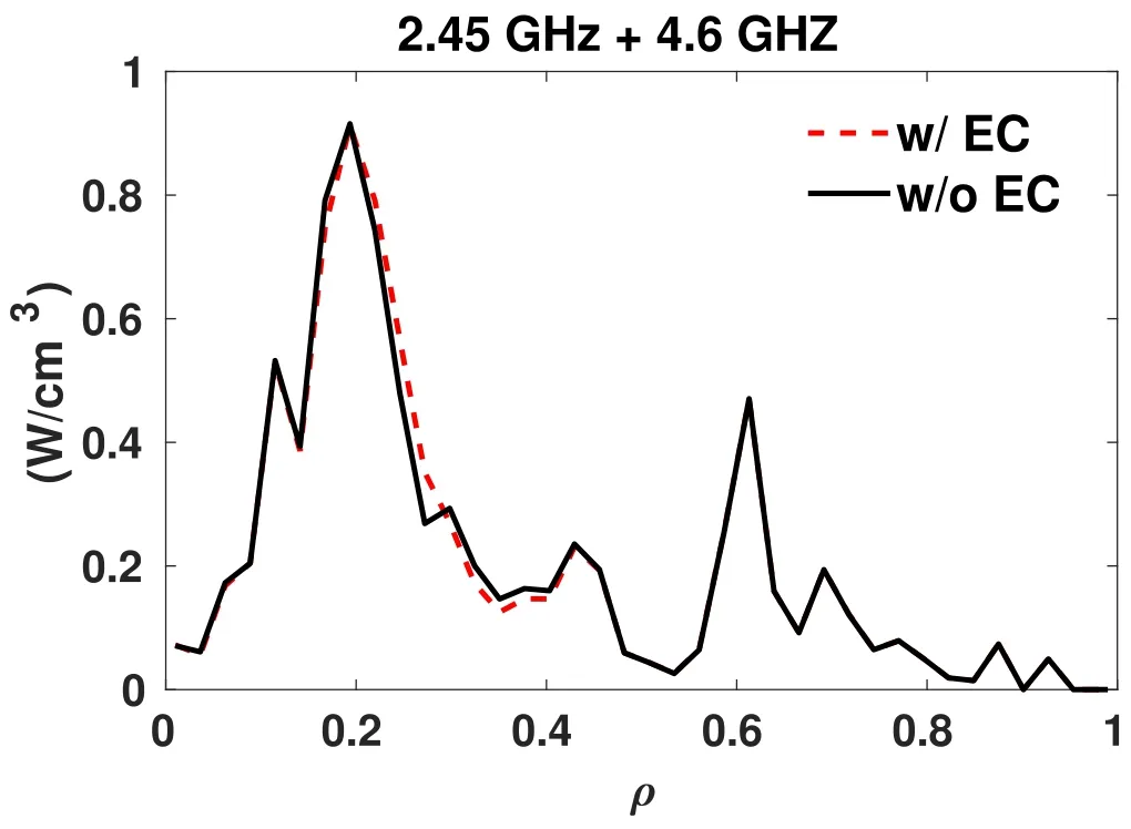


3.3.Influence of relativistic effect on total current


3.4.Relativistic effect on EC resonance layers
4.Summary
猜你喜欢
杂志排行

Plasma Science and Technology的其它文章
- Numerical simulation of nanosecond laser ablation and plasma characteristics considering a real gas equation of state
- The propagation dynamics and stability of an intense laser beam in a radial power-law plasma channel
- Effect of edge magnetic island on carbon screening in the J-TEXT tokamak
- Influence of the X-point location on edge plasma transport in the J-TEXT tokamak with a high-field-side single-null divertor
- A simulation study of protons heated by left/right-handed Alfvén waves generated by electromagnetic proton–proton instability
- Investigation of optimum discharge characteristics and chemical activity of AC driven air plasma jet and its anticancer effect