Effect of edge magnetic island on carbon screening in the J-TEXT tokamak
2022-01-10XiaolongZHANG张晓龙ZhifengCHENG程芝峰SongZHOU周松YunfengLIANG梁云峰WeiYAN严伟NengchaoWANG王能超XiaoyiZHANG张霄翼ZhongheJIANG江中和ZhoujunYANG杨州军XinXU徐鑫DaLI李达QiongLI李琼XiaodongLIN林晓东YonghuaDING丁永华ZhongyongCHEN陈忠勇ZhipengCHEN陈志鹏andT
Xiaolong ZHANG(张晓龙),Zhifeng CHENG(程芝峰) ,Song ZHOU(周松),Yunfeng LIANG (梁云峰),4, Wei YAN (严伟), Nengchao WANG (王能超),Xiaoyi ZHANG (张霄翼), Zhonghe JIANG (江中和), Zhoujun YANG (杨州军),Xin XU (徐鑫), Da LI (李达), Qiong LI (李琼), Xiaodong LIN (林晓东),Yonghua DING(丁永华),Zhongyong CHEN(陈忠勇),Zhipeng CHEN(陈志鹏) and J-TEXT Team,5
1Advanced Energy Research Center,Shenzhen University,Shenzhen 518060,People’s Republic of China
2 Key Laboratory of Optoelectronic Devices and Systems of Ministry of Education and Guangdong Province, College of Optoelectronic Engineering, Shenzhen University, Shenzhen 518060, People’s Republic of China
3 State Key Laboratory of Advanced Electromagnetic Engineering and Technology, School of Electrical and Electronic Engineering, Huazhong University of Science and Technology, Wuhan 430074, People’s Republic of China
4 Forschungszentrum Jülich GmbH, Institut für Energie und Klimaforschung-Plasmaphysik, 52425 Jülich,Germany
Abstract The effect of externally applied resonant magnetic perturbation (RMP) on carbon impurity behavior is investigated in the J-TEXT tokamak.It is found that the m/n=3/1 islands have an impurity screening effect, which becomes obvious while the edge magnetic island is generated via RMP field penetration.The impurity screening effect shows a dependence on the RMP phase with the field penetration, which is strongest if the O point of the magnetic island is near the low-field-side(LFS)limiter plate.By combining a methane injection experimental study and STRAHL impurity transport analysis, we found that the variation of the impurity transport dominates the impurity screening effect.The impurity diffusion at the inner plasma region(r/a<0.8) is enhanced with a significant increase in outward convection velocity at the edge region in the case of the magnetic island’s O point near the LFS limiter plate.The impurity transport coefficient varies by a much lower level for the case with the magnetic island’s X point near the LFS limiter plate.The interaction of the magnetic island and the LFS limiter plate is thought to contribute to the impurity transport variation with the dependence on the RMP phase.A possible reason is the interaction between the magnetic island and the LFS limiter.
Keywords: magnetic island, impurity transport, resonant magnetic perturbation, boundary plasma physics, J-TEXT tokamak
1.Introduction
Impurities affect plasma equilibrium, degrade plasma confinement, and even excite magnetohydrodynamic instability,leading to plasma disruption by increasing plasma radiation loss and resistivity.Thus, great efforts have been taken to reduce plasma impurity concentration on most magnetic confinement devices.Effectively controlling impurity is particularly critical for the International Thermonuclear Experimental Reactor(ITER)to achieve its desired fusion gain goal with limited auxiliary heating capacity [1].
The magnetic field geometry is considered to play an important role in plasma particle control due to the strong anisotropy of particle transport with respect to magnetic field vectors.Thus, the possibility of controlling the edge plasma behavior by changing the edge magnetic field structure has been studied in several devices, e.g., LHD [2, 3], TEXTORDED [4, 5], and DIII-D [6].In these cases, the external magnetic coils,named resonant magnetic perturbation(RMP)or dynamic ergodic divertor(DED)coils,are used to offer the RMP, which leads to near-field effects forming chains of magnetic islands.The magnetic island chains may overlap,resulting in a strong modification of the original magnetic structure [7].
In TEXTOR-DED operation,a so-called Pump Out effect was found, which is also observed in DIII-D [8], EAST [9],and JET [10] during edge-localized mode (ELM) mitigation experiments with RMP, characterized by a decrease in the plasma density.The Pump Out effect appears in J-TEXT RMP experiments withm/n=2/1 field penetration [11].However, underm/n=3/1 RMP, the electron density is found to increase in some scenarios due to the enhanced edge recycling [12].
Under the same regime, impurity behavior has also been found to be effectively affected by RMP on various devices[13–15].It is widely reported that the impurity concentration is reduced with the introduction of RMP in both L- and H-mode plasma.Carbon decontaminations in the core plasma are observed under various RMP modes in TEXTOR[16]and LHD[17].Fluorine concentration is found to be reduced in a DIII-D ELM suppression experiment by RMP [18].Furthermore, RMP is reported to reduce the concentration of higher charge impurities, such as argon/iron in TEXTOR [19], and tungsten/iron in EAST [20].
The role of RMP in reducing the impurity concentration is explored from the perspectives of the impurity transport and impurity source.In the TEXTOR-DED experiment with the basic mode ofm/n=3/1, a reduction in carbon con
finement time proportional toIDEDagrees with a diffusiondominated analytical model, whereIDEDis the coil current[16].Changes in the effective radial transport caused by classical parallel diffusivity along the stochastic field lines are believed to account for the changes in particle(and impurity)transport [21].The RMP-induced magnetic island may modify the electron or ion flow toward the wall,resulting in a change in the radial electric field [19].The possible mechanisms of the RMP effect on impurity transport are also reported in [22–24].In DIII-D, STRAHL code is applied to simulate the fluorine emissivity evolution in the RMP ELMsuppressed plasma [16].The impurity convection is found to become slightly positive due to the strong ion temperature gradient,which acts to screen impurities.The larger diffusion coefficientD∼5–10 m2s−1is also favorable for reducing impurity concentration.In EAST H-mode plasmas,the RMPs increase the diffusion coefficient and the outward convective velocity through the STRAHL simulation for iron spectra(Fe20+12.88 nm, Fe21+11.63 nm, Fe22+13.29 nm) [13].
Since the outward flux is significantly modified by RMP,it also affects the plasma–wall interaction and the production of impurity at the boundary.Strong local recycling is generally observed with the enhanced outward flux in DIII-D[25, 26], J-TEXT [12], MST [27], etc.The experimental results on DIII-D show that gross erosion differs significantly(>50%) at the different toroidal phases of the RMP field,consistent with a substantially three-dimensional (3D)impact [28].
The RMP coils on the J-TEXT could work at various RMP modes providing flexible experimental conditions to explore the RMP effect on the impurity transport.This paper specifically investigated the edge magnetic island topology’s impact on the carbon source (limiter) and the impurity transport correspondingly.The structure of the paper is as follows.In section 2, the experimental setups are given, and then the experimental results are described in section 3.In section 4, the carbon transport coefficients are analyzed with STRAHL code, and the effect of 3/1 magnetic island on a low-field-side (LFS) limiter is discussed.The paper is summarized in section 5.
2.Experimental setup
J-TEXT(formerly TEXT-U)is a conventional tokamak with a silicon carbide graphite limiter[29–31].It has a major radius of 1.05 m and a minor radius of 0.25–0.27 m.The typical discharge parameters are as follows:plasma current 100–220 kA,toroidal field 1.4–2.2 T, and line-averaged electron density(1–6) × 1019m−3.There are two sets of resonant magnetic perturbation coils constructed on the J-TEXT tokamak, which are placed around the torus uniformly [32–34].As shown in figure 1(a),the RMP system consists of 24 saddle coils divided into two groups colored blue and red,respectively.Figure 1(b)shows the spectrum of the RMP field when the 3/1 RMP component is dominant.The parameter φois defined to characterize the phase of the 3/1 magnetic island under the vacuum assumption.It refers to the toroidal angle of the O point for the 3/1 magnetic island with the poloidal angle at θ=0°, i.e.in the LFS mid-plane.The phase of φo=0 is as marked in figure 1(a).The RMP amplitude and the spatial phase can be adjusted by changing the coil current and configuration.In the study, various 3/1 RMP configurations are applied to investigate the impurity behaviors.

Figure 1.(a) Layout of the RMP coils on the J-TEXT tokamak;(b) spectrum of the perturbation field when 3/1 RMP is dominant.

Figure 2.Layout and composition of the spectral diagnostic system on the J-TEXT tokamak.The yellow and green blocks denote the carbon V and carbon VI diagnostics in the HFS of port 1,respectively;the three blue blocks(A,B,C)denote the carbon III diagnostics in the HFS of port 4, LFS of port 4, and HFS of port 10, respectively; the red block denotes the high-resolution spectrometer in the horizontal plane of port 3; the purple block denotes the vacuum ultraviolet (VUV) spectroscopy diagnostic; the black blocks in the left figure represent the layout of the three limiters; and the black point in port 10 represents the position of the supersonic molecular beam injection (SMBI) nozzle.
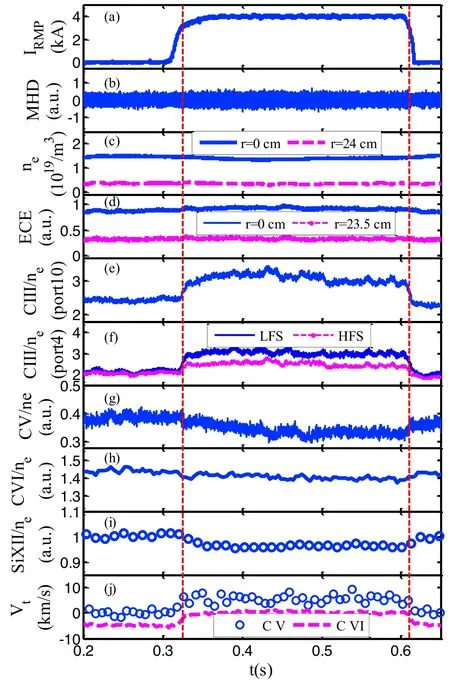
Figure 3.Evolution of plasma parameters at shot 1053337.(a)RMP current,(b)Mirnov coil signal,(c)line-averaged density at r=0 cm(blue) and r=24 cm (pink), (d) central and edge ECE signal, (e)carbon III signal(r=24 cm)at HFS of port 10(as shown in figure 2 blue area C), (f) C III signal at the HFS (r=24 cm, pink) and LFS(r=24 cm, blue) of port 4 (as shown in figure 2 blue areas A and B), (g) ratio of C V to electron density (r=20 cm) at the HFS of port 1(as shown in figure 2 yellow area),(h)ratio of C VI to electron density(r=15 cm)at the HFS of port 1(as shown in figure 2 green area), (i) ratio of silicon XII to electron density measured by VUV diagnostic, and (j) toroidal rotation velocity of C V and C VI.The red dotted lines indicate the beginning and the end of 3/1 penetration.

Figure 4.(a) Current of RMP; evolution of the ratio of IC V/IC III(blue dotted line) and IC VI/IC III (red dots) with IRMP=4 kA,IC V/IC III(black line)with IRMP=2 kA.(b)Statistical relationship between ratio of IC V/IC III and RMP current; red dashed line indicates the threshold of 3/1 penetration.

Figure 5.Different island phase effects on impurity line emission.(a) ICV/ne; (b) IC III/ne (φo=−24°: red dotted line, φo=−54°:cyan line, φo=126°: blue dashed line, φo=156°: black dashdotted line).

Figure 6.Normalized statistical results of RMP phase (φo) and relative variation of the IC V/ne and IC III/ne with 3/1 locked magnetic island induced by the RMP penetration.The blue dotted line indicates the LFS limiter position.
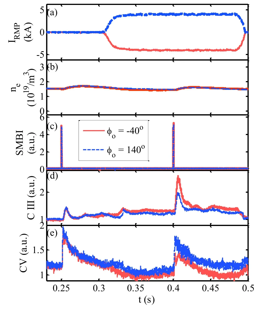
Figure 7.Evolution of plasma parameters after SMBI injection under RMP at φo=−40° in shot 1062736 (red) and φo=140° in shot 1062760 (blue).(a) RMP current; (b) SMBI signal; (c) center lineaveraged density; (d) C III signal at r=24 cm; (e) C V signal at r=20 cm.(IP=170 kA, BT=1.7 T, ne=1.5×10¹⁹/m3.)
With the graphite limiter and graphite tiles fully covering the vacuum wall at the high-field side (HFS), it is expected that abundant carbon impurities exist in the J-TEXT plasma.Since the typical electron temperature is about 800–1000 eV in the core and 10–50 eV near the last closed flux surface(LCFS)in the J-TEXT plasma,the carbon ions can distribute across a relatively wide radial range in the plasma, making them a good candidate for the impurity study.We have developed a spectral diagnostic system to observe carbon ions.It consists of carbon V (C V 227.09 nm), carbon III(C III 464.7 nm),and carbon VI(C VI 529.26 nm)diagnostics[35], as shown in figure 2.Two identical 18-channel photodiode arrays with the specified front C III filter (center wavelength of 466 nm, bandwidth of 5 nm) at port 4 are dedicated to measuring the C III emission in the HFS and LFS.The spatial resolution, time resolution, and coverage area of the C III diagnostic are 13 mm, 100 μs, andr=7–29 cm,respectively.The C V and C VI diagnostics are developed to measure the inner carbon emission profile.The high-resolution spectroscopy system consists of a 1.33-mfocal-length monochromator, an ANDOR EMCCD camera with 1024×1024 pixels each of size 13 μm×13 μm,and a fiber-optic light collection system with 16 viewing channels.It is adjusted to measure the spectra of C III(229.69 nm)and C V (227.09 nm) at the LFS, which can provide the carbon emission intensity and rotation as required.
A space-resolved vacuum ultraviolet (VUV) spectroscopy system based on a 1 m normal incidence spectrometer has been developed on the J-TEXT tokamak[36,37]to observe the highly ionized impurity closer to the plasma center.In this experiment,the VUV diagnostic is set to observe silicon XII (49.9 nm).
The electron density profile comes from a laser-based polarimeter–interferometer system (POLARIS) [38, 39]; the electron temperature profile comes from electron cyclotron emission(ECE)[40];and the ion temperature comes from an X-ray imaging crystal spectroscopy system [41] for Ar16+in the core and high-resolution spectroscopy diagnostic [42,43]for C2+or C4+near the edge.Furthermore, a supersonic molecular beam injection (SMBI) system is applied to inject impurity gas in this experiment [44, 45].The injector is equipped at the bottom of port 10 with a pre-filled gas pressure of 1.0 MPa, which can inject 0.8×10¹⁹particles through a 0.5 ms pulse in this experiment.
3.Experimental results
3.1.Impurity behavior under 3/1 RMP
In order to understand the edge impurity behavior under the 3/1 RMP, the line emission signals from multiple ionized carbon and silicon XII are collected for comparison under various RMP parameters.Taking the typical discharge 1053337 as an example (plasma parameters:Ip=170 kA,BT=1.75 T,qa∼3.2), we can find that a 3/1 locked magnetic island is induced due to the 3/1 RMP penetration when the current intensity exceeds a certain value(∼3 kA),as shown in figure 3.In this case, a rapid change of toroidal impurity rotation is found, where a typical rise of∼5–8 km s−1in the co-current direction for the C V(or C VI)rotation appears.A slight decrease (<5%) is observed in the center line-averaged density characterized by POLARIS, but no significant variation is observed in the electron temperature characterized by ECE.
All impurity line emission signals are presented with the ratio to the local density to eliminate the signal deviation from density variation, which provides a more reasonable evaluation of the impurity concentration.In figure 3, the C III intensity near the plasma boundary (figures 3(e) and (f))increases by 30%–50%while the RMP penetration happens at 0.325 s.This means that the carbon accumulates near the LCFS.The C III signal is commonly believed to represent the amount of carbon source at the plasma edge.It is also found that the variations of C III signals at different toroidal andpoloidal positions are not the same(port 10 CIII:30%,port 4 LFS CIII:50%,port 4 HFS CIII:35%),which is thought to be caused by the 3D effect of the 3/1 magnetic island at the edge region.The role of the 3/1 magnetic island on C V (atr∼20 cm) and C VI (atr∼15 cm) emission is relatively weak.After the formation of the 3/1 locked magnetic island,the C V intensity has a slight decrease(∼10%);for C VI,the intensity decreases by ∼5%.The silicon XII emission measured by VUV diagnosis also decreases slightly (∼5%) after the formation of the 3/1 locked island.This means that all the observed impurity contents at the inner place reduce, suggesting that the edge magnetic island may benefit the impurity exhaust.This may be attributed to the impurity screening effect [16, 19, 46].
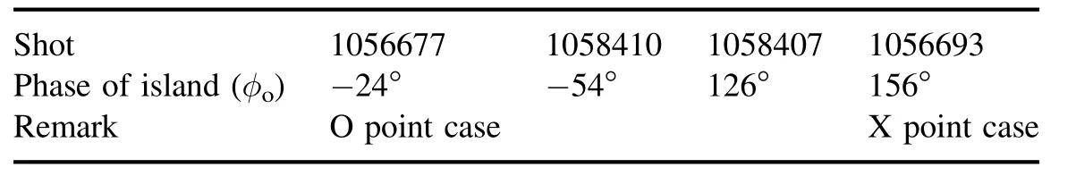
Table 1.RMP phase configuration.
The emission intensity ratio of the inner impurity(C V or C VI) and the outer impurity (C III) is used to reflect the carbon screening effect, as shown in figure 4.Since the 3D edge magnetic topology leads to an asymmetric C III distribution, the C III signal is deduced by averaging the C III signals from multiple places.It is found that the impurity screening effect increases with an increase in RMP current,showing a decline in the ratioICV/ICIII.The effect appears much more sensitive on the RMP penetration, withIRMP≥3.2 kA, corresponding to the further significant drop after the red dashed line in figure 4(b).The RMP phase is found to impact the impurity screening effect as well,showing that the normalized ratio ofICV/ICIIIin the case with φo=134° RMP penetration is higher than that with φo=66°.
3.2.Effects of different phases on impurity behavior
With the localized limiters in the J-TEXT vacuum vessel, a quick assumption is that the 3D plasma configuration caused by the edge magnetic field will lead to various interactions with the vacuum material (limiter material) under different RMP phases.Thus,the impurity source may be coupled with the RMP phase.To explore the detailed impacts, we compared the carbon impurity behaviors under four different RMP phases with φo=−24°, 156°, −54°, and 126°.The detailed RMP configurations are presented in table 1.The LFS limiter is located at the mid-plane of port 14(as shown in figure 2), and the corresponding toroidal angle is −22.5°.It can be seen that the O point of the magnetic island is closest to the LFS limiter (referred to as the O point case) under the phase φo=−24°;the X point is closest to the LFS limiter at φo=156° (referred to as the X point case).
The evolutions of C V and C III signals in the four RMP phases are presented in figure 5, where the RMP fields are added at the same time as in figure 3.It is shown that the intensity of C III in the O point case(φo=−24°)and X point case (φo=156°) increases by ∼40% and ∼20%, respectively.The variations of C III intensity at φo=−54° and 126°are at the intermediate values.However,the evolution of the C V signal shows the opposite trend.C V emission at phase φo=156°remains almost constant,but drops the most at φo=−24°, indicating the strongest impurity screening effect among the four cases.
By modifying the RMP coil connection configuration,we can obtain multiple 3/1 RMP phases.Figure 6 presents the relative variation of C V and C III emission with the scanned RMP phases, where the plasma parameters are fixed asIP=170 kA,BT=1.7 T, andne=(1.2–1.5)×1019/m3.The field penetrations are induced using the same RMP strength with a coil current of 4 kA.The dependence of the carbon emission on the RMP phase can be well described by ΔI/ne=b+ksin(φo+α) for both C V and C III, wherek,a, andbare constants.However, the φodependence is opposite for the two impurity ions, i.e.αCIII–αCV∼180°.This clearly shows the dependence of the carbon emission on the RMP phase, where the evolutions of C V and C III variation both follow the cosine function, but in the opposite phases.The cycle length is 360°, in line with the toroidal mode number (n=1) of the RMP field.

Figure 8.(a)C V emission evolution after SMBI methane injection.0 s means the injection time.Red dashed line denotes the e-exponential fitting.(b) Statistical results of decay time of C V emission and RMP current (blue squares: φo=140°; black circles:φo=−40°; red dashed line denotes the threshold of 3/1 penetration).
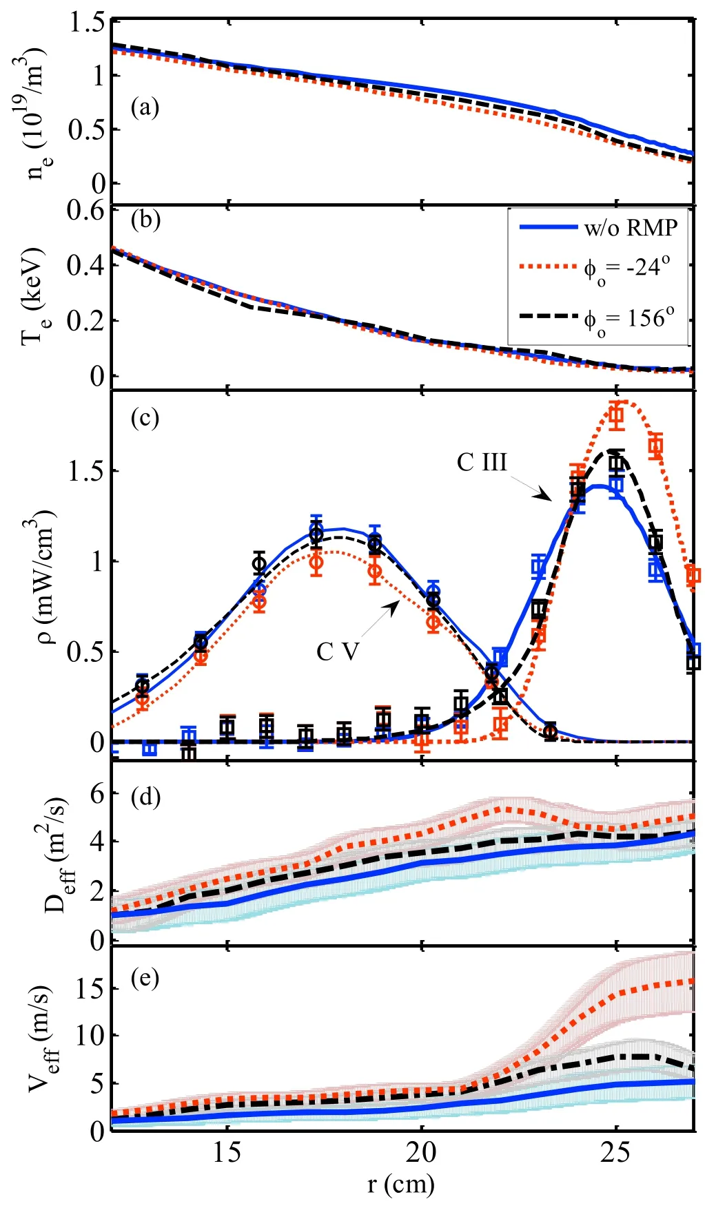
Figure 9.(a) Density profile; (b) electron temperature profile; (c)measured results(point type)and simulated results(line type)of C V and C III emission profile; (d) carbon impurity effective diffusion coefficient;(e)carbon impurity effective convection coefficient.The three cases are distinguished by different colors: w/o RMP (blue),RMP at φo=−24°(red),and RMP at φo=156°(black).The light color represents the error bars of the transport coefficients due to errors in the impurity line emission profiles.
It was found previously in J-TEXT that the three graphite limiters contribute to the carbon source at different levels.Generally, the horizontal limiters offer more carbon impurity than the other two vertical limiters [35].The HFS limiter is removed in the latest experiments on the J-TEXT tokamak;thus, the LFS limiter is believed to be a main-limiter which provides the most carbon source and has the strongest interaction with edge plasma.
Regarding the opposite phases for C V and C III variation, one possible reason is that the plasma temperature near the O point is higher than that at the X point, leading to a stronger interaction between the LFS limiter and plasma,producing a higher carbon source.However, in fact, the impurity screening effect caused by the enhanced outward carbon impurity flux will result in carbon accumulation at the edge region,which can also lead to a stronger C III intensity.
3.3.Impurity transport investigation with active carbon source
To specify the impurity screening effect dependence on the magnetic island phase, we applied the SMBI system to actively inject methane (CH4), achieving a constant external carbon source pulse.The SMBI injection position is at the bottom of port 10, as shown in figure 1.Figure 7 shows the methane injection results at φo=−40° with the O point of the magnetic island close to the LFS limiter plate and at φo=140° with the X point of the magnetic island close to the LFS limiter plate.It could be seen that the spike of C III caused by the SMBI injection with 3/1 locked magnetic island at 0.4 s, is obviously higher than that without RMP at 0.25 s.For C V, the phenomenon is in the opposite trend,where the height of the C V spike with RMP penetration is lower than 75% of that without RMP.This demonstrates that the 3/1 RMP-induced magnetic island can effectively block the carbon impurity from entrancing the bulk plasma, which is typically described as the impurity screening effect[16, 46].In line with the previous conclusion, while the O point is closer to the LFS limiter,the impurity screening effect is stronger.

Figure 10.Poincaré plot of the magnetic fields at the limiter position.The poloidal angle of 0° indicates the LFS, (a) φo=−24°;(b) φo=156°; (c) φo=−54°; (d) φo=126°.
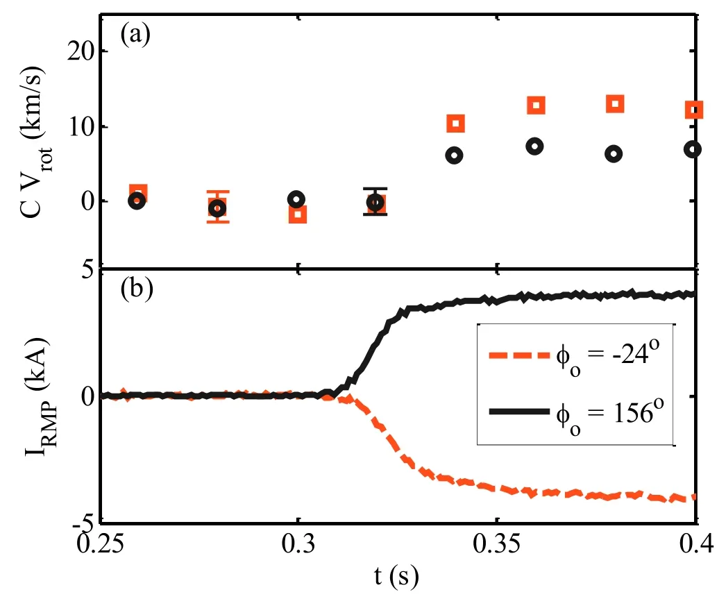
Figure 11.(a) C V rotation in the case of RMP at φo =−24° (red squares) and φo=156° (black circles).(b) IRMP (φo=−24°: red dashed line; φo=156°: black line).
The methane injection by SMBI can induce a transient carbon accumulation in the plasma, as shown by the rapid formation of the C V signal spike.In this case, the signal decay time is commonly used to evaluate the impurity confinement [47–49].The declining period is believed to be dependent on the effective diffusion coefficient as follows:

whereakis the parameter related to the device, and τdecayis the impurity decay time which is defined in the exponential expression as

As shown in figure 8(a),the short segments after the peak on the C V signal are chosen to fit the exponential function,and hence to deduce the impurity decay time for the three cases.According to the statistical results of τdecayshown in figure 8(b),the impurity decay time shows the dependence on the RMP current.In the φo=−40° case, the decay time drops most after the RMP penetration.
4.Discussion
The SMBI experimental results show that the C III spike with RMP penetration is obviously higher than that without RMP,representing the effect of blocking carbon impurity from entering the bulk plasma.From the transport perspective, the convection at the plasma periphery (r>22 cm) is enhanced,and the direction of convection is outward.In the inner region, the impurity decay time drop indicates an enhancement of the impurity diffusion.
For a clearer depiction of the experimental results,STRAHL code is used to simulate the variation of impurity transport coefficient with the application of RMP in the edge region.STRAHL code is capable of modeling impurity transport in one-dimensional space[35,50,51].It obtains the density distribution of each ionization state and the impurity line emission profile by solving the radial continuity equations.The transport coefficient will be iterated until the measured emission profile of impurity is reproduced.For a charge stageZ,the coupled radial impurity transport equation can be expressed as

whereDis the diffusion coefficient, andVis the convective velocity inside the tokamak plasma (a positive velocity point to the wall).The source or sink termQis determined by the atomic process of each ionization stage.
During the simulations, the background plasma parameter profiles(electron temperature,electron density,etc)are provided as input.The impurity line emission profile measured by diagnostics is also needed for comparison.In the J-TEXT plasma, carbon impurity is the main target to be monitored by the impurity line emission diagnostic,and the C III and C V emission profiles can be derived from chordintegral spectral signals with Abel-like inversion [35].
The cases without RMP and with RMP penetration at φo=−40° and φo=140° are compared, as shown in figure 9.The electron density profile in figure 9(a)is provided by POLARIS, and the electronic temperature profile in figure 9(b)is obtained from ECE.The C V and C III emission profiles are composed of two parts:one is the inversion of the impurity line emission signal measured by diagnostics (point type pattern in figure 9(c)); the other is the STRAHL simulation result (line type pattern in figure 9(c)).It should be noted that in this work the C III emission profile is obtained by averaging the C III from multiple places to fit the onedimensional code, providing a general idea of the RMP role.Thus, the deduced transport coefficients are described as the effective diffusion coefficient and the effective convection coefficient, presented in figures 9(d) and (e), respectively.Constrained by the C V and C III emission bands, the effective region is approximately fromr=12 cm tor=27 cm.It is obvious that the effective carbon diffusion coefficient in the case φo=−40° is higher than that in the case φo=140°, which is slightly enhanced compared with the case without RMP.The effective convection velocity at the periphery is much higher with RMP penetration at φo=−40°, consistent with the conclusion of SMBI experimental results.
Various studies have reported the transport change with edge magnetic island [13, 14, 19].One idea is that the enhanced transport is due to the higher radial fraction of the parallel transport with the modified magnetic field topology.The edge magnetic island may also affect the turbulence behavior in the inner region, thus resulting in a difference in impurity transport.Furthermore, it is typically found that the radial electric field is impacted by RMP, due to the unbalanced particle loss [19].
According to the experimental results in J-TEXT, the impurity behavior dependence on the phases of the 3/1 magnetic island is thought to be the result of the interaction between the magnetic island and the LFS limiter.As shown in figure 10,Poincaré plots of the magnetic fields under the four RMP phases (table 1) are calculated by the nonlinear 3D equilibrium response of the resonant magnetic perturbation field code at the poloidal cross-section in which three limiters are located[52,53].The magnetic field lines are partially cut off by the limiter, especially for the case φo=−24°.This is somewhat similar to the effect of the magnetic island divertor,which is dedicated to achieving a better impurity exhaust[54–57].For other phases, the magnetic field lines are less cut, leading to a weaker impurity screening effect.
As reported on many devices, in the magnetic island divertor configuration, a large positive electric field with a sharp radial electric field shear is observed, which is considered to be produced by electron loss along the magnetic field line towards the limiter plate[58–60].In LHD,the radial electric field shear at the boundary is believed to contribute to trigger the formation of an internal transport barrier in the electron root plasma.The role of the radial electric field is found to be quite important in preventing the influx of impurities and avoiding radiative collapse.The positive electric field observed in the magnetic island divertor configuration is considered to play an important role in impurity screening [58].
In the J-TEXT plasma, the change of radial electric field can be indicated by the plasma rotation evolution.As presented in figure 11, in the case φo=−24°, the C V rotation increases by ∼11 km s−1, compared to ∼8 km s−1for φo=156°.Due to the effect of E×B, the change of the radial electric field will cause a change in the impurity rotation speed [58, 61].The modification is in the co-current (IP)direction, indicating the growth of the outward radial electric field.The electric field may directly enhance the radial particle transport via the classic transport scheme or change the transport through the coupling effect of plasma rotation and turbulence [58, 59].
5.Summary
The 3/1 RMP is applied to generate the edge magnetic island on J-TEXT.The carbon impurity behavior is found to be affected by the magnetic island, showing the impurity screening effect with the radiation behavior of carbon impurity.The screening role shows a dependence on the phase of the magnetic island with a stronger impurity screening effect while the O point is approaching the LFS limiter plate.In SMBI methane injection experiments,the C V decay time is reduced with the occurrence of the 3/1 magnetic island, especially for the case with the O point near the LFS limiter plate.Combined with the STRAHL simulation, it is concluded that the carbon diffusion is enhanced in the inner region.By comparing the C III signals in the various cases, the edge magnetic island is thought to lead to a high outward convection velocity at the edge region.The radial electric field variation due to the interaction of the magnetic island and the LFS limiter plate,which can be described as the partial magnetic island divertor configuration, is preliminarily thought to be the key for the impurity transport variation.
The detailed impurity behaviors with the edge magnetic island will be studied with the foreseen introduction of 3D impurity transport code, such as EMC3.Moreover, the synthetic effect of the electric field, turbulence, and plasma rotation should be taken into account in further studies, to achieve a deeper understanding of the role of the edge magnetic island.
Acknowledgments
This work was supported by the National Key R&D Program of China (Nos.2017YFE0301301 and 2017YFE0302000),National Natural Science Foundation of China (Nos.11805135 and 11805131), and the Ministry of Science and Technology (No.2015GB103001).The Shenzhen Clean Energy Research Institute is appreciated.The authors thank all the staff of J-TEXT for their advice and help in analysis of experimental results.
ORCID iDs
猜你喜欢
杂志排行

Plasma Science and Technology的其它文章
- Numerical simulation of nanosecond laser ablation and plasma characteristics considering a real gas equation of state
- The propagation dynamics and stability of an intense laser beam in a radial power-law plasma channel
- Relativistic effect on synergy of electron cyclotron and lower hybrid waves on EAST
- Influence of the X-point location on edge plasma transport in the J-TEXT tokamak with a high-field-side single-null divertor
- A simulation study of protons heated by left/right-handed Alfvén waves generated by electromagnetic proton–proton instability
- Investigation of optimum discharge characteristics and chemical activity of AC driven air plasma jet and its anticancer effect