Friction and Wear Behaviors of C/C-SiC Composites under Water Lubricated Conditions
2020-06-04GAOWenYANGFan
GAO Wen(高 雯), YANG Fan(杨 帆)
1 Nuclear Power Institute of China, Chengdu 610213, China 2 Chengdu Metro Operation Company, Chengdu 610000, China
Abstract: C/C-SiC composites have the potentiality to be applied in shield pumps of nuclear reactors as the bearing material because of their low density, good mechanical properties and excellent tribological properties. The C/C-SiC composites are fabricated via reactive melt infiltration (RMI) using silicon liquid infiltrated in C/C matrix composites. Friction and wear behaviors of C/C-SiC composites under water lubricated conditions are investigated using the block-on-ring test at room temperature, and compared with those of the resin graphite which is used as the bearing material in shield pumps at present. In addition, friction and wear mechanisms of C/C-SiC composites under water lubricated conditions have been discussed. Results show that tensile strengths of C/C-SiC composites are 150-210 MPa, and compressive strengths are 403-536 MPa. Friction and wear behaviors of C/C-SiC composites are closely related to the load and the speed. The time to reach a stable friction status decreases with the increase of the speed. Though the friction coefficient of C/C-SiC composites under water lubricated conditions is slightly higher than that of graphite, the wear rate of C/C-SiC composites is much lower, which suggests that the C/C-SiC composites can sustain a longer life during operation.
Key words: C/C-SiC composites; reactive melt infiltration(RMI); friction; wear; lubrication
Introduction
C/C-SiC composites have been widely applied as friction materials for brake discs and brake pads in aircraft, rocket and automotive industries due to their excellent mechanical properties[1-3], such as higher density ( about 2.0 g/cm3), longer service life, and higher thermal shock resistance[4]. It is reported that C/C-SiC composites have lower sensitivities to the environment and temperatures when the percentage of silicon carbide is higher than 20%[5]. In the past ten years, researches on C/C-SiC composites have mainly focused on the tribological behavior in different environments as brake materials, and have never been considered their potential use as bearing shells for shield pumps in marine engineering, petrochemical processing and even nuclear reactors.
It is known that one of the most critical problems limiting the lifetime of shield pumps is the service life of the bearing materials. The commonly used bearing material is mainly graphite which is frequently damaged. It has been reported that the shield pumps are frequently broken due to the failure of graphite bearings, and their broken ratio has reached about 30.8% in recent years, especially in nuclear power plants[6]. Once the pump failes, the reactor should be immediately shut down, which means that the whole nuclear power plant should be stopped until the problem is fixed. Generally, it will take at least one month before the reactor restarts, which means a loss of money. Thus, in order to improve the economic effectiveness of a nuclear reactor as well as to reduce the cost, it is necessary to develop a modified candidate which has better properties.
In this study, friction and wear behaviors of C/C-SiC composites under various loads and speeds in water lubricated conditions have been investigated and compared with those of the graphite. In addition, the friction and the wear mechanisms of C/C-SiC composites under water lubricated conditions have been discussed.
1 Experiments
1.1 Materials
The carbon pad was produced by carbon fibers, and each sheet was woven in 0° or 90° direction alternately, as shown in Fig. 1. Afterwards, it was needle-punched to make layers connect to each other in order to form carbon matrices. The volume composition of carbon fiber is about 30%, and the density is 0.5 g/cm3. Chemical vapor infiltration (CVI) was applied to fabricate the preform C/C composite. Firstly, the preform C/C composite was put in kerosene vapor environment at 1 100 ℃ for 6.5 h. Then it was graphitized in argon gas environment at 2 300 ℃ for 2 h. Finally, reactive melt infiltration (RMI) was applied to manufacturing C/C-SiC composites by putting the C/C composites in liquid silicon at 1 550 ℃ for 30 min. The chemical composition of the obtained C/C-SiC composites is shown in Table 1, which is a bit higher than that obtained in the past.

Fig. 1 Sketch of the woven carbon pad
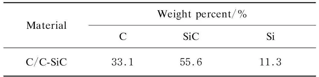
Table1 Chemical composition of C/C-SiC composites
1.2 Characterization
Friction and wear tests were carried out on an MRH-3 high speed block-on-ring tribometer with C/C-SiC composites at a dimension of 12 mm×12 mm×19 mm. The corresponding ring of 40Cr stainless steel which was coated with 3 mm thick nickel alloy had an outside diameter of about 49 mm and an inside diameter of 35 mm. The schematic diagram of the block-on-ring tribometer is shown in Fig. 2.
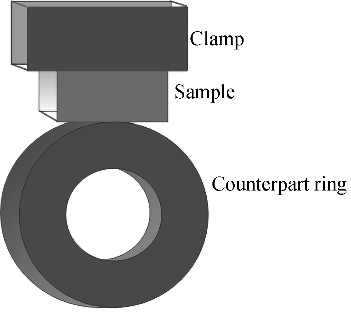
Fig. 2 Diagram of the block-on-ring tribometer
Experiments were performed at different speeds from 200 r/min to 800 r/min, and the loads of 100, 200, 300, and 400 N were applied, respectively. Each test lasted about 7 200 s. All the tests were performed under water lubricated conditions of 120- 150 water drop per minute. The friction coefficient was measured by an online data acquisition system attached to the tribometer, and the average friction coefficient was obtained. The wear rate was obtained by the volume lossVk, which could be calculated by[7]
(1)
where,Dis diameter of the counterpart ring;tis width of the wear scar;Bis width of the sample.
The microstructure of the obtained C/C-SiC composites and the morphology of worn surfaces and wear debris were examined by DMI5000M optical microscopy, FEI Nova nanometer scanning electron microscopy (SEM) and vantage type energy dispersive X-ray analysis (EDAX).
2 Results
2.1 Microstructure and mechanical properties
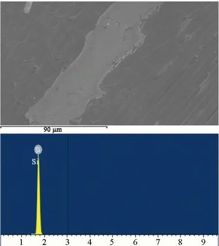
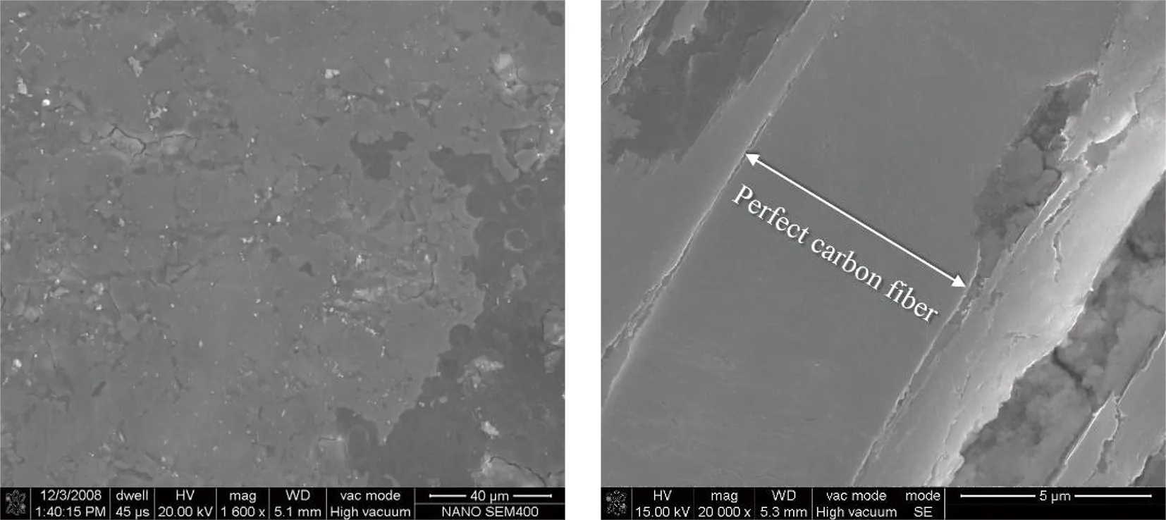
The fabricated C/C-SiC composites have dense and uniform microstructure, as shown in Fig. 3. It is obvious that the C/C-SiC composites are composed of fiber layers in 0° and 90° directions. From the EDAX results, it can be seen that the bright white region is residual Si (shown in Fig. 3(c)), and the light gray region at the edge of the residual Si is SiC (shown in Fig. 3(b)).
(a)
(b)
(c)
Fig. 3 Microstructure of C/C-SiC composites: (a) cross-section view; (b) EDAX around carbon fibers; (c) EDAX of other fibers
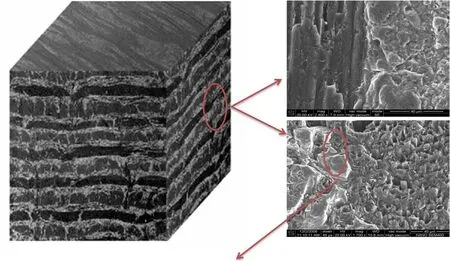
The mechanical properties of the obtained C/C-SiC composites are listed in Table 2. Their tensile strength is 150- 210 MPa, which is about 3- 4 times higher than that of the graphite used as bearing material at present. The compressive strength changes from 403 MPa to 536 MPa, the Rockwell hardness is 71.8-74.2 HRB, the fracture toughness is 7.3-9.2 MPa·m1/2, and the impact strength is 20.1-33.1 kJ/m2. The impact strength of the C/C-SiC composites is much higher than that of the graphite which is generally used as the bearing material of the shield pump in the first loop. The fracture toughness of graphite is less than 1 MPa·m1/2[8]. This is possibly attributed to the addition of carbon fibers whose strength is higher than that of the matrix. When the crack expands to the carbon fibers, its expanding direction changes, and the fibers are extracted from the matrix. During this course, the stress concentration energy will be released from the crack tip. The fracture surface of C/C-SiC composites has verified this process, as shown in Fig. 4.
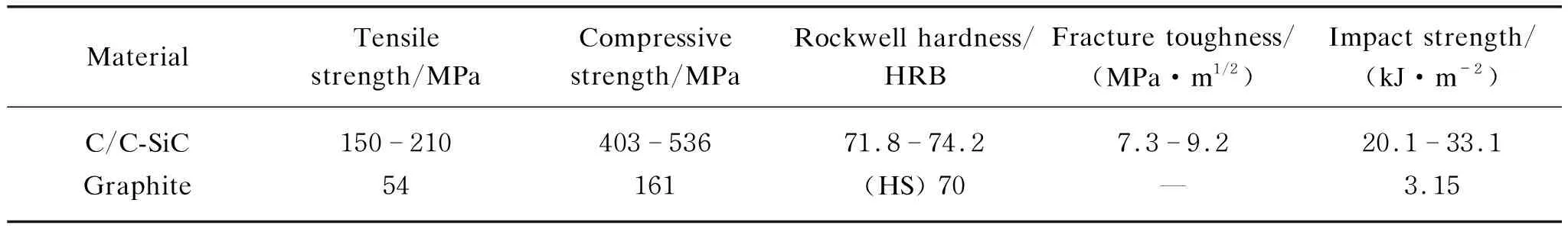
Table 2 Mechanical properties of C/C-SiC composites and graphite
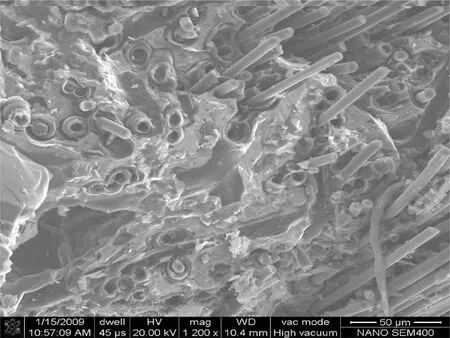
Fig. 4 Fracture morphology of C/C-SiC composites after the impact fracture test at room temperature
2.2 Friction coefficient and wear rate
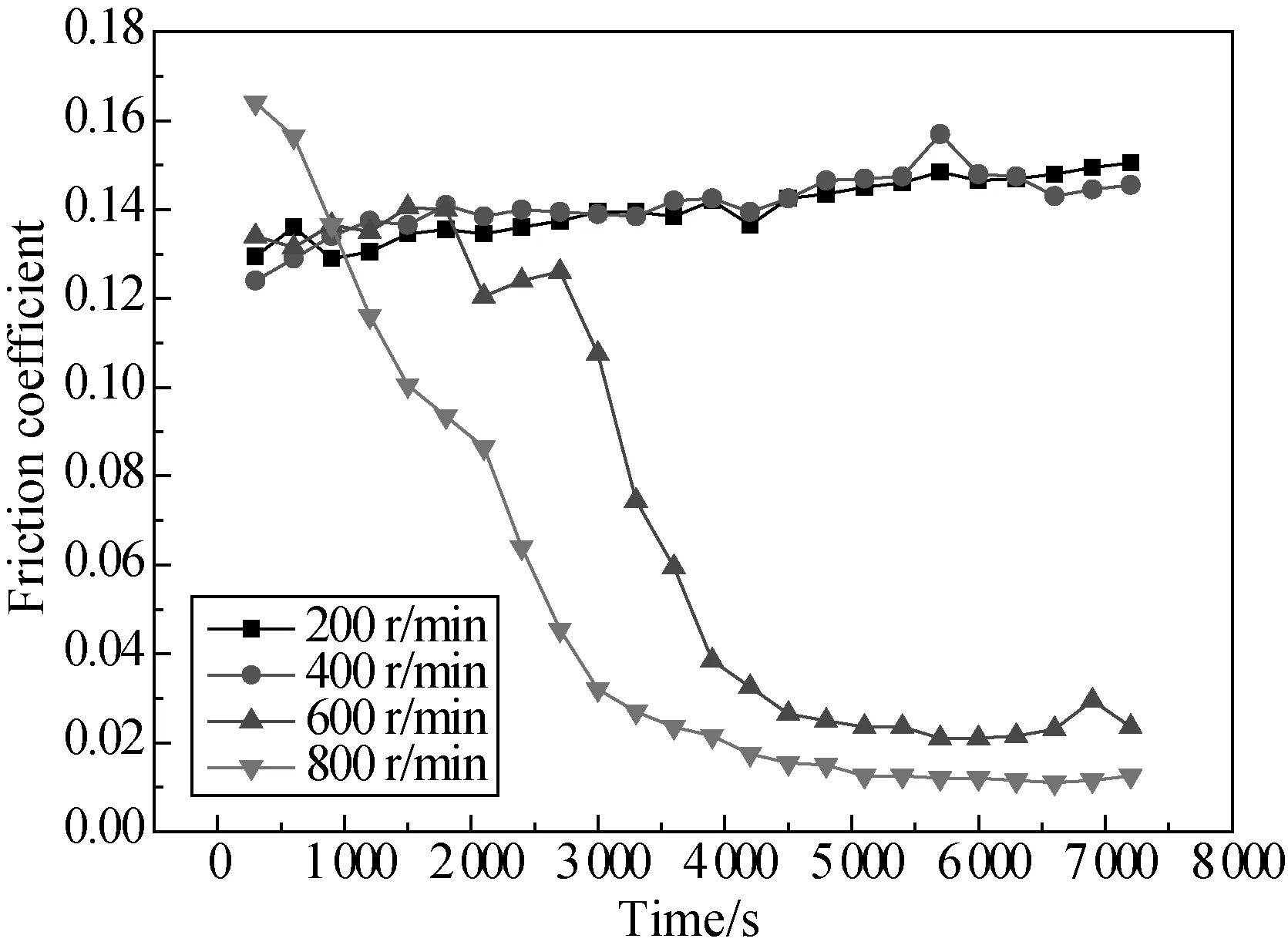
Friction and wear performances of C/C-SiC composites under water lubricated conditions are shown in Figs. 5 and 6. It is obvious that the friction coefficient decreases as the rotating speed increases, under various loads except 400 N. Especially when the rotating speed is over 400 r/min, a perfect water lubricating film has been formed. The friction coefficient decreases to a stable value which is about 0.050, 0.030, and 0.025 at 100 N, 200 N and 300 N at the speed of 600 r/min, respectively. When the speed increases to 600 r/min, the friction coefficient gradually decreases, and it decreases to a lower value of 0.010 when the speed is over 800 r/min. Attention should be paid to the test at the load of 400 N, in which the friction coefficient does not decrease greatly. It is because the load is too high to allow the formation of the water lubricating film. It should also be noticed that the time used to reach a stable friction increases with the increase of load, which means that it needs longer time to form the water lubricating film under higher loads. At the load of 100 N, it needs only about 2 000- 3 000 s. However, when the load increases to 200 N, the time changes to about 4 000 s at the speed of 600 r/min, and 3 000 s at the speed of 800 r/min. When the load continuously increases to 300 N, the time required becomes 6 000 s at the speed of 600 r/min and 4 000 s at the speed of 800 r/min.
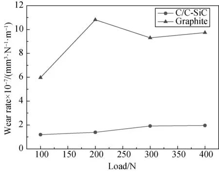
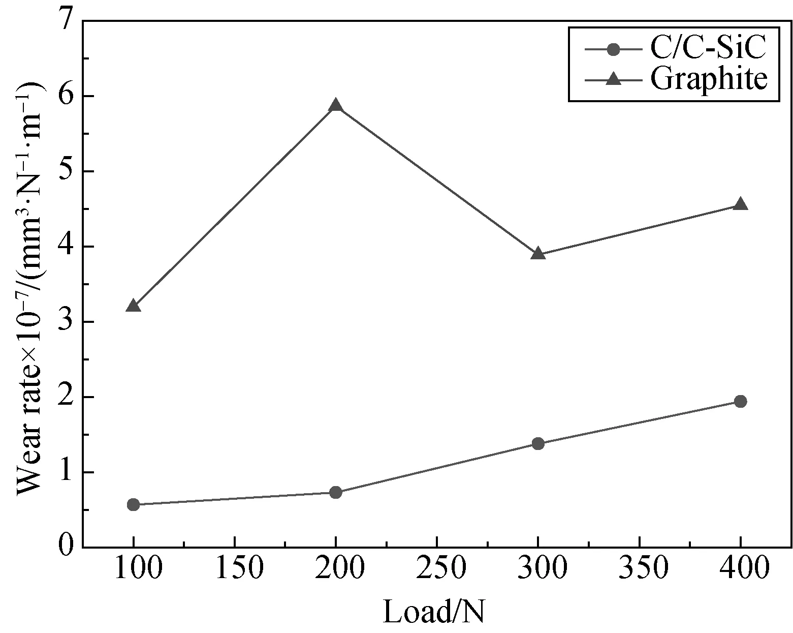
Figure 6 shows that the wear rate increases with the increase of the load, and generally decreases with the increase of the speed. At a speed of 200 r/min, the wear rate increases from 1.6×10⁻⁷mm3/(N·m) to 3.4×10⁻⁷mm3/(N·m) when the load increases from 100 N to 400 N. At a speed of 400 r/min, the wear rate does not change a lot, and it only increases from 1.2×10⁻⁷mm3/(N·m) to 1.6×10⁻⁷mm3/(N·m) when the load increases from 100 N to 400 N, which means a perfect water lubricating film has been formed at this condition. The lowest wear rate has been obtained at the following conditions: the load is less than 200 N and the speed is over 600 r/min, at which a stable water lubricating film can be formed.

(a)
(b)

(c)
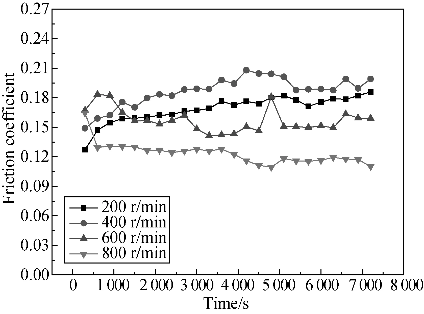
(d)Fig. 5 Friction coefficient of C/C-SiC composites under different loads: (a) 100 N; (b) 200 N; (c) 300 N; (d) 400 N
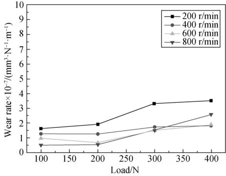
Fig. 6 Wear rate of C/C-SiC composites
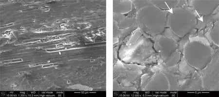
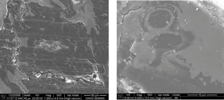
The morphology of the worn surface under different loads is shown in Fig. 7. At the load of 100 N, no carbon fibers are broken, while lots of flocculent carbon debris has been observed on the worn surface, as shown in Fig. 7(a). The carbon fibers start to be extracted, broken and damaged at the load of 200 N, and the carbon debris from the deposited carbon around the carbon fiber has been observed, as shown in Fig. 7(b) (white arrows). At the load of 400 N, cracks start to be observed, and deep scratches are found. In some regions, carbon and silicon start to wear off, and more and more deposited carbon debris is found on the worn surface, as shown in Fig. 7(c). This is the reason that the friction coefficient increases with the load increase. Especially for the specimen tested at the load of 400 N, some furrows can be seen clearly on the worn surface. In this case, water plays no lubricating function since the contact stress at the wear interface is too high to allow the formation of water lubricating film, and it only plays the role of cooling. More details can be found in the discussion section.
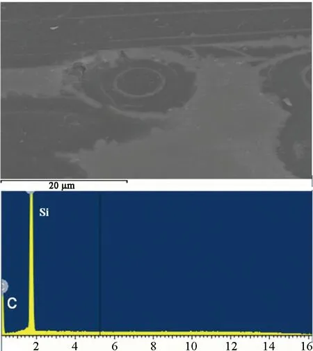
From the EDAX result shown in Fig. 8, it can be seen that the formed debris is mainly composed of Si and SiC. A mass of SiC particles can act as hard points to cut the surface, and then the softer carbon matrices are flaked off to form the new debris. This course repeats again and again during friction and wear processes, which might be the main friction and wear mechanism for C/C-SiC composites at the test conditions.
Low magnification High magnification
(a)
(b)
(c)Fig. 7 Worn surface of C/C-SiC composites underdifferent loads at the speed of 200 r/min:(a) 100 N; (b) 200 N; (c) 400 N
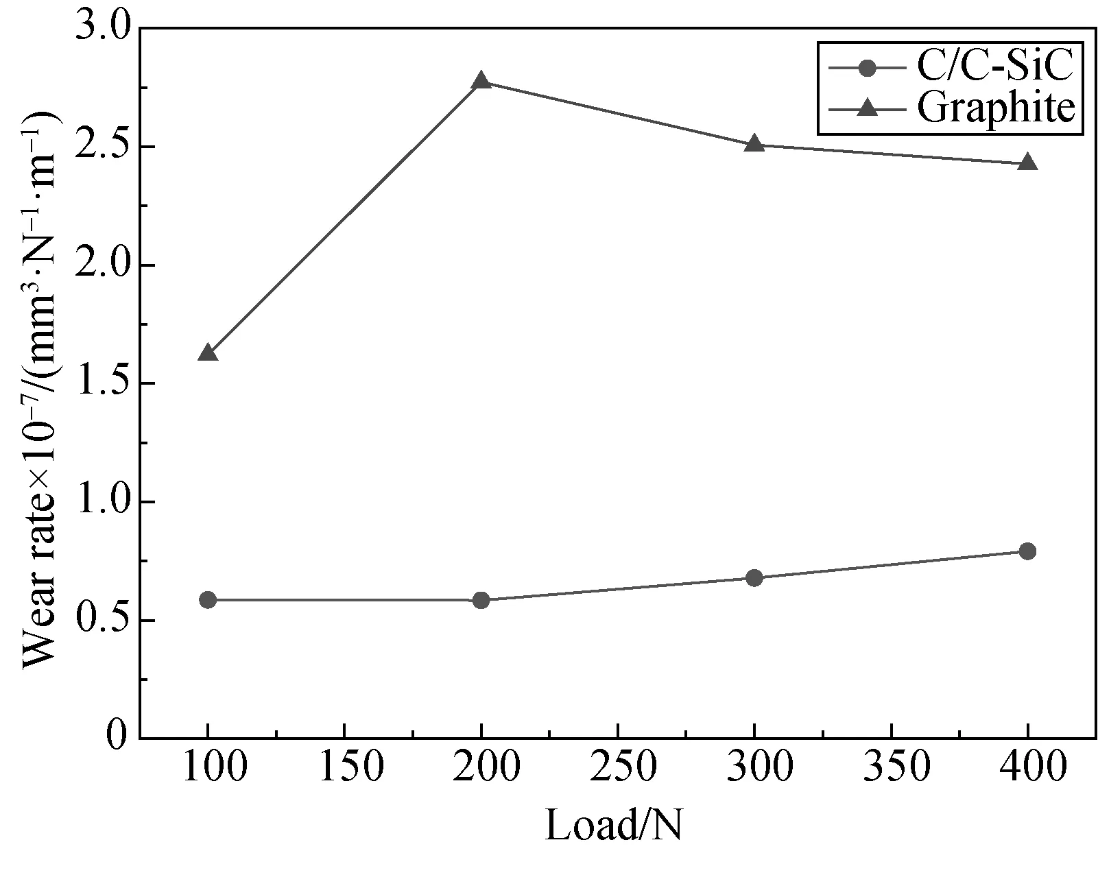
The C/C-SiC composites show better wear behaviors compared with graphite which is the most often used in shielding pumps of nuclear reactors, as shown in Fig. 9.
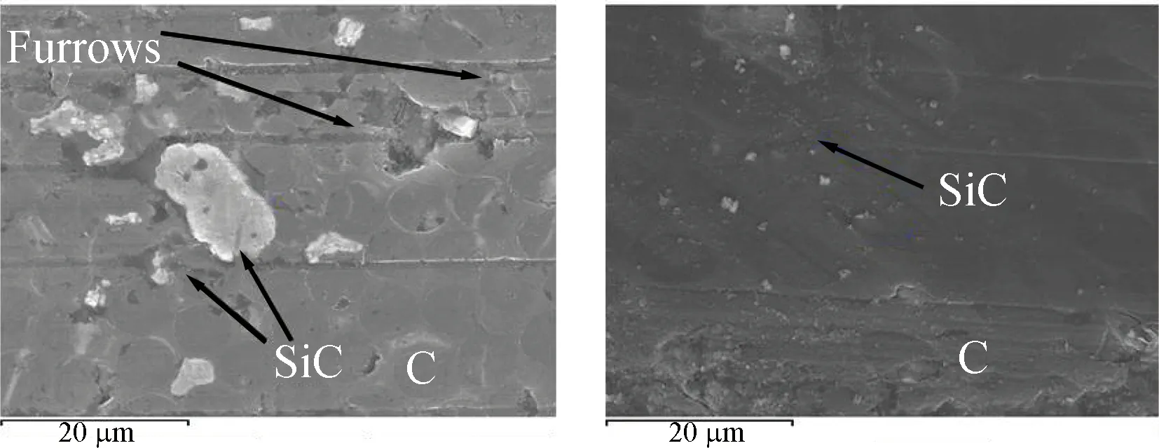
Fig. 8 EDAX result of worn surface of C/C-SiC composites at the speed less than 400 r/min and at the load of 400 N
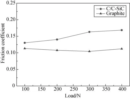
At the same test conditions, although the friction coefficient of C/C-SiC composites is slightly higher than that of graphite (shown in Fig. 10), the wear rate of C/C-SiC composites is much less than that of graphite, which may result from the SiC phase and carbon fibers with higher strengths. It can be also found in Fig. 10 that the friction coefficient of C/C-SiC composites increases more significantly than that of the graphite with the increase of load.
(a)
(b)
(c)
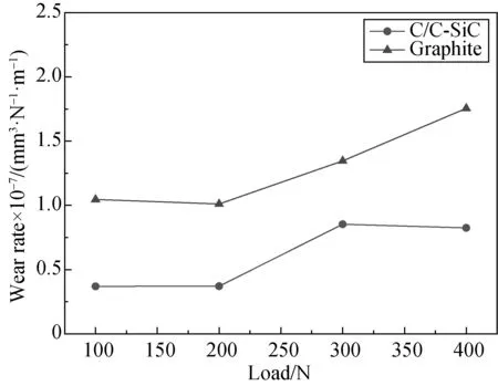
(d)Fig. 9 Wear rate of C/C-SiC composites and graphite under different rotating speeds:(a) 200 r/min; (b) 400 r/min; (c) 600 r/min; (d) 800 r/min
(a)
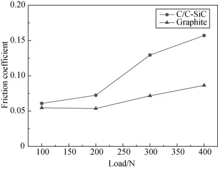
(b)Fig. 10 Friction coefficient of C/C-SiC composites and graphite under different rotating speeds: (a) 200 r/min; (b) 600 r/min
3 Discussion
The friction contact area is changing during friction and wear processes. Thus the real contact stress should be analyzed to obtain a more precise evaluation of the lubricated friction and wear properties of C/C-SiC composite.
According to Hertz theory[9], the distribution of initial stress and the elastic deformation in the contact area between the block and the ring can be simulated as the contact of an elastic column and a rigid plane. When a loadWis applied, the contact stress distributes as a half oval shape, and can be expressed by
(2)
The maximum Hertz stress can be expressed as
p0=2W/(πbl),
wherebis the half indentation width.
The main stress at such status is alongz-axis. Then the force stress of the friction system can be calculated by[10]
(3)
whereFis the force, andδis the stress.
The original width of the friction scratch can be described by[10]
(4)
where,Sis the original width of friction scratch;Lis the height of friction ring;Ris the radius of the curvature;Eis the elastic modulus. The original width of the friction scratch is about 0.10 mm at 100 N, 0.15 mm at 200 N, 0.19 mm at 300 N, and 0.21 mm at 400 N. The original contact stress is calculated, and the value is 8.2-41.6 MPa at 100 N, 12.2-55.2 MPa at 200 N, 14.4-67.6 MPa at 300 N, and 17.3-77.9 MPa at 400 N. ANSYS numerical simulation has also been applied to confirming the result. The analysis results are less than the calculated ones. This is mainly due to the formation of water lubricating film. Table 3 contains the data of the contact stress in the original status and the contact stress during friction movement, which is simulated by the ANSYS software.
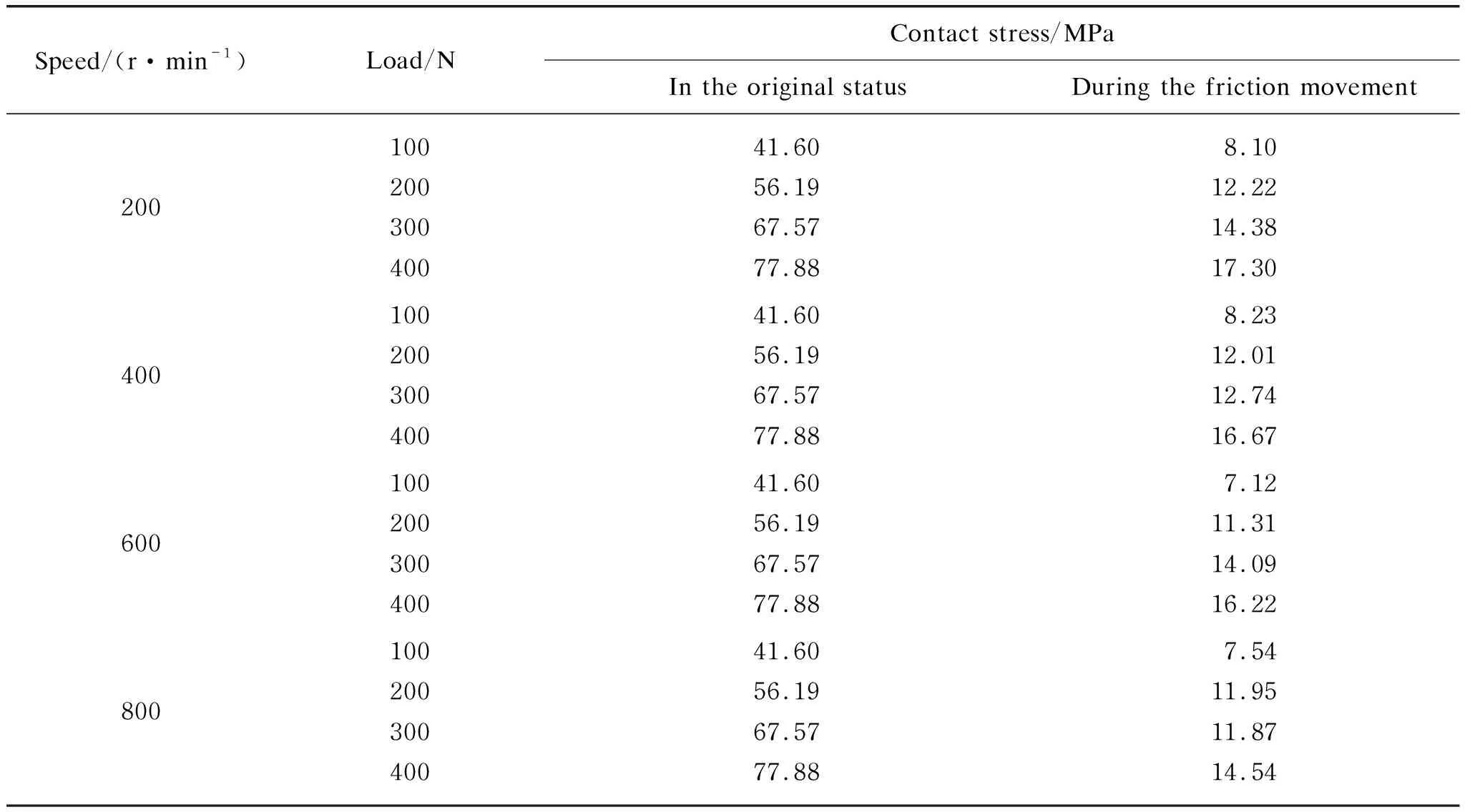
Table 3 Contact stresses in the original status and during the friction movement simulated by the ANSYS software
It can be observed that the carbon matrix, SiC and Si all play an important role in friction and wear processes. The friction coefficient increases a little bit at first due to the contact of two different surfaces, and then it decreases because the water lubricating film is gradually formed during the friction movement, which smooths the contact reaction between the two surfaces. Then the asperities on the surface start to break with wearing, and thus the abrasive particles such as C and SiC are formed. It means that all the requirements for abrasive wear have been met, and thus the wear rate of C/C-SiC composites increases. Besides, a lot of furrows are induced by the SiC particles. The softer C particles can be pressed into the friction surface, and more and more flaky abrasive dust will be formed on the surface as shown in Fig. 8.
4 Conclusions
In this study, the fabricated C/C-SiC composites are composed of carbon fibers, porous carbon, SiC and Si. The tensile strengths are 150 -210 MPa, the compressive strengths are 403-536 MPa, the hardnesses are 71.8-74.2 HRB, the fracture toughnesses are 7.3-9.2 MPa·m1/2, and the impact strengths are 20.1-33.1 kJ/m2.
In water lubricated conditions, the friction coefficient decreases with the increase of speed when the speed is over 400 r/min and the load is less than 300 N. The wear rate of C/C-SiC composites increases with the increase of the load, and decreases with the increase of the speed. The lowest wear rate is obtained when the load is less than 200 N and the speed is over 600 r/min, at which a stable water lubricating film can be observed. In fact, the stable water lubricating film starts to form when the speed is over 600 r/min.
Friction and wear mechanisms of C/C-SiC composites are mainly abrasive wear because a lot of furrows, SiC particles, Si particles and C particles are found on the worn surface. The C/C-SiC composites have better behaviors compared with graphite in shield pumps of nuclear reactors.
杂志排行

Journal of Donghua University(English Edition)的其它文章
- Acoustic Performance of Green Composites for Chinese Traditional Percussion Drums
- Fabrication and Characterization of Polypyrrole/Polyurethane/Polyamide/Polyamide Yarn-Based Strain Sensor
- Performance Analysis of Cushioned Sport Soles with Plantar Pressure Test
- Existence Criterion of Three-Dimensional Regular Copper-1, 3, 5-Phenyltricarboxylate (Cu-BTC) Microparticles
- Combining User-Driven Social Marketing with System-Driven Personalized Recommendation for Student Finding
- Generative Adversarial Network with Separate Learning Rule for Image Generation