Fabrication and Characterization of Polypyrrole/Polyurethane/Polyamide/Polyamide Yarn-Based Strain Sensor
2020-06-04LITingLIQiao
LI Ting(李 婷), LI Qiao(李 乔)*
1 Key Laboratory of Textile Science & Technology, Ministry of Education, Shanghai 201620, China 2 College of Textiles, Donghua University, Shanghai 201620, China
Abstract: Yarn-based strain sensors serve as essential elements for wearable electronics in the applications of personal health monitoring, motion detection, and smart garments. In the paper, a yarn-based strain sensor was created by coating conductive polymer, polypyrrole(PPy), onto a double covered elastic yarn, i.e., polyurethane/polyamide/polyamide (PU/PA/PA) yarn. Surface morphology of the yarn-based strain sensors demonstrates that the PPy conductive particles are evenly distributed on the surface of the PA multi-filaments as well as immersed into the PU core. Cyclic tensile test is conducted to characterize the electro-mechanical performance of the yarn-based strain sensor. The mechanical hysteresis of the sensor is low, which mainly comes from the geometrical change of the PA filaments around the PU core. However, the electro-mechanical hysteresis of the sensor is large mainly due to the unrecoverable cracks of the PPy layers on the PU core.
Key words: strain sensor; flexible electronics; hysteresis; cyclic loading
Introduction
Yarn-based resistive strain sensors, which convert external strain stimulus into resistance change on the basis of resistance-strain effect, are essential elements for flexible and wearable electronics. Superiority of textile substrates in flexibility, deformation and lightweight makes the textile-based strain sensors effective in real-time physiological condition and motion monitoring[1-4].
Previous researches on yarn-based sensors mainly focus on improvement of their working range and sensitivity by new substrates and novel manufacturing processes. It has been demonstrated that the structure and the performance of the elastic substrates are essential to the sensing capabilities of the sensors. Basically, three categories of substrates were adapted for textile-based strain sensors. Initially, yarn-based strain sensors were produced by blending rigid metal wires around one elastic core yarn[5-6]. For instance, Schwarz-Pfeifferetal.[6]produced strain sensors with rubber or rubber blended yarns as the core, and stainless-steel wire or copper wire as the sheath or covering layer. A conductive model was established according to Kirchhoff’s law, concluding that the contact resistance between the covered metal wires was very small so that the working range of such sensors was limited. In addition, rigid metal wires in the assembly hindered the wearable application of sensors. In order to improve the stretchability or the working range of the yarn-based strain sensors, the second method is to directly coat the conductive materials on the elastic core yarn. The strain sensors are comparatively softer than rigid metal wires, enabling large stretchability of the strain sensors[7-8]. However, the sensors with conductive materials coated onto the pure elastic core yarn suffered poor reproducibility due to the weak interfacial bonding between the conductive layer and the pure core yarn. At present, double covered elastic yarns(DCYs) are often used as the yarn substrate for the coated strain sensors, in order to enhance their bonding force between the conductive materials and the yarn substrate. For this kind of yarn-based strain sensors, conductive polymers, carbon materials,etc. were used as conductive elements. It has been proved that covered elastic yarn-based strain sensors could be stretched more than 60% strain with a large working range and sufficient sensitivity. However, some other sensitive performances, such as repeatability and hysteresis, of the strain sensors should be emphasized and enhanced for wearable applications[9-11].
We firstly fabricate a yarn-based strain sensor by coating conductive polymer, polypyrrole (PPy), onto a DCY,i.e., polyurethane/polyamide/polyamide (PU/PA/PA) yarn, by in-situ polymerization. Surface morphology of the formed yarn-based strain sensors was observed by a scanning electron microscope(SEM). Cyclic tensile tests were then conducted to characterize the electro-mechanical performance of the yarn-based strain sensor, followed by analyses on the sensing mechanism by surface observation of the yarn-based strain sensors under different tensile strains.
1 Experiments
1.1 Materials
The selection of the elastic yarn and conductive polymer is essential to make a yarn-based strain sensor with good electro-mechanical performance. A DCY,i.e., an elastic core with PU multifilament covered by two layers of spirally wound polyamide filaments (PU/PA/PA), was selected as the elastic yarn substrate for the strain sensor due to its excellent stretchability. The linear densities of PU, PA in the first layer and PA in the second layer are 420, 40 and 20 D, respectively. Pyrrole was used to create PPy-coated strain sensors (PPy/PU/PA/PA) with relatively high conductivity of the PPy conductive material and low cost.
1.2 Fabrication process
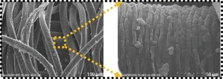
The fabrication process of the PPy/PU/PA/PA yarn-based strain sensor is schematically shown in Fig. 1. It generally consists of two major steps,i.e., alkali treatment and in-situ polymerization. The DCY was firstly immersed in a NaOH solution with a concentration of 1 mol/L for 1 h, rinsed with distilled water, and then immersed in a mixed solution of pyrrole and sodium anthraquinone-2-sulfonate monohydrate (AQSA) under 0 ℃ for 1 h, in which the concentrations of pyrrole and AQSA were 0.12 mol/L and 0.01 mol/L, respectively. Then the FeCl3solution (0.18 mol/L) was dropped into the mixed solution through a burette, where the volume ratio of the FeCl3solution to the mixed solution is 1∶1. After that, the reaction solution was placed in an ice bath (0 ℃) for 2 h, and the sample was rinsed with distilled water until no black fragment. Finally, it was dried in an oven at a temperature of 80 ℃ for 20 min.
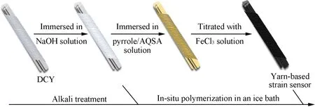
Fig. 1 Fabrication process of PPy/PU/PA/PA yarn-based strain sensor
1.3 Characterization
Surface morphology was observed under an SEM (Flex 1000, Hitachi High-Technologies Co., Ltd., Japan).
Tensile tests were conducted to evaluate the electro-mechanical behavior of the yarn-based strain sensor. Based on the test methods of FZ/T 50007—2012 and GB/T 14337—2008, the fiber strength meter (XQ-2, Shanghai New Fiber Instrument Co., Ltd., Shanghai, China) was used to conduct the cyclic loading test, and the data acquisition instrument (Agilent 34970A, Agilent Technologies, USA) was utilized to acquiring the electrical resistance of the yarn-based sensor with a scanning interval of 160 ms. The gauge length is 10 mm, and the tensile speed is 20 mm/min. During the test, all the samples were firstly pre-treated under a constant elongation of 100% with five cycles for stabilization of the electro-mechanical behavior of the sensors. Then, all the samples were stretched to 60% strain for ten times to obtain stress-strain and resistance-strain curves.
Based on the obtained stress-strain and resistance-strain curves, both mechanical and electro-mechanical hystereses of the yarn-based strain sensors were calculated. Mechanical hysteresisHFwas defined as the maximum force difference at the same strain during one up-loading and down-loading cycle:
(1)
where, ΔFmaxis the maximum force change between the stretching and the recovery processes; (Fu-Fd)maxis the maximum force change at a certain strain during the cycle. For the electro-mechanical hysteresisHR, the dependent variable was changed to resistance of the sensor:
(2)
where,ΔRmaxis the maximum resistance change between the stretching and the recovery processes; (Ru-Rd)maxis the maximum resistance change at a certain strain during the cycle.
2 Results and Discussion
2.1 Surface morphology
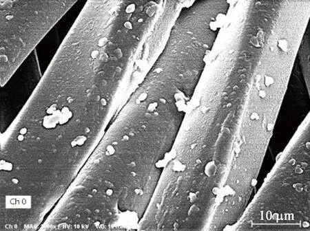
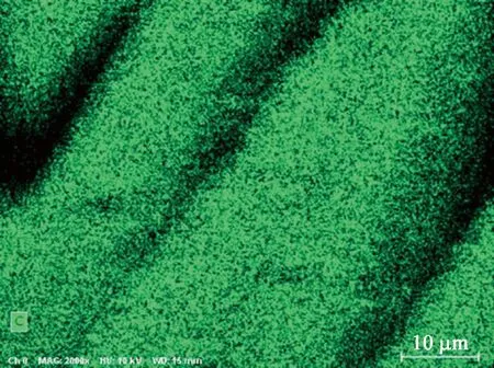
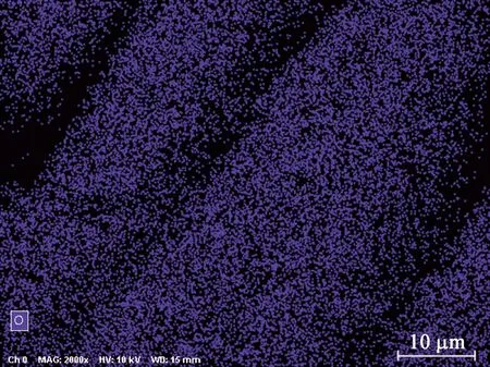
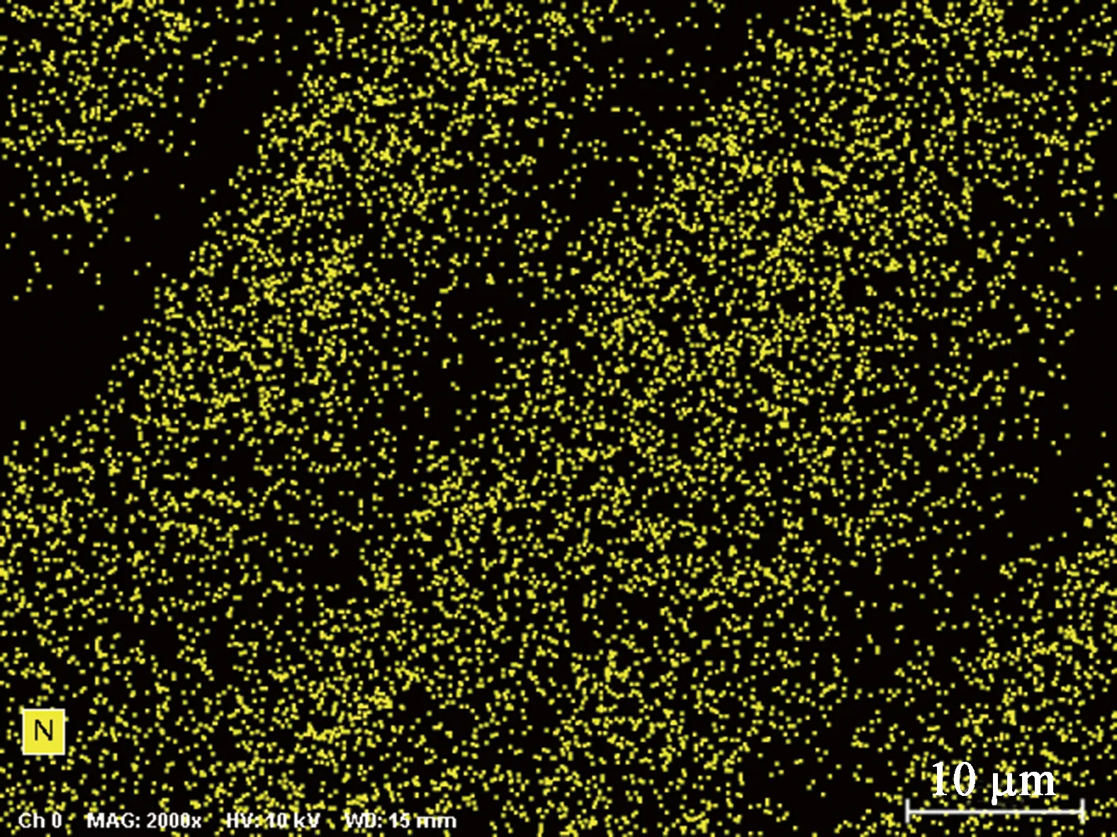
Surface morphology of the DCY and the PPy-coated DCY sensor is shown in Fig. 2. The surface of DCY samples shown in Fig. 2(a) is comparatively smoother than that of the PPy-coated DCY sensor shown in Figs. 2(b) and (c). With the treatment of PPy coating, a new conductive layer was formed by the conductive polymer, adhering to the surface of both PA filaments and the inner PU core. It demonstrates that PPy can be polymerized on the surface of the PA sheath, also pass through the inherent pores of the DCY structure and coat on the PU core. Figure 2(b) indicates that the polymerized PPy is evenly distributed on the surface of the outer PA filaments, which could be proved by the distribution of elements in the energy spectra as shown in Fig. 3. Nitrogen is the characteristic element of PPy, of which the relatively uniform distribution proves the uniformity of the conductive layer on the surface of the PA filaments.
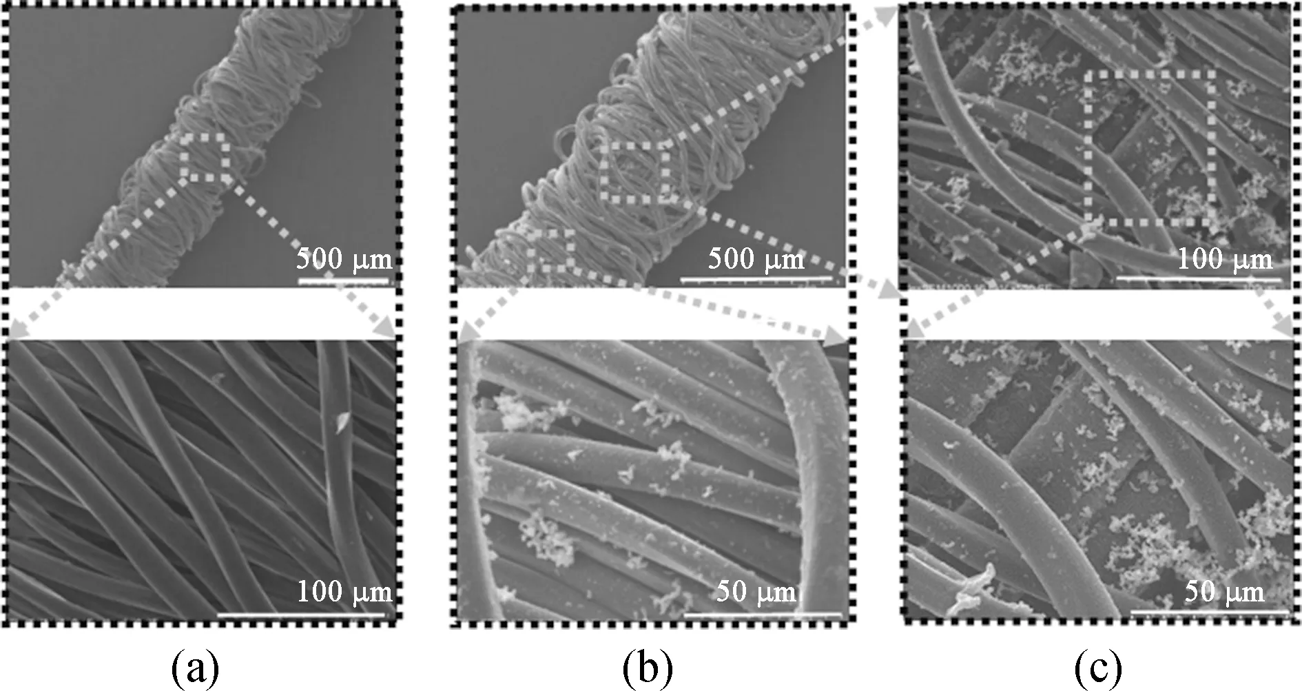
Fig. 2 SEM images of (a) DCY; (b) and (c) PPy-coated DCY sensor
(a)
(b)
(c)
(d)
Fig. 3 Surface energy spectra of the PPy-coated DCY sensor: (a) SEM image; (b) element C; (c) element O; (d) element N
2.2 Electro-mechanical performance
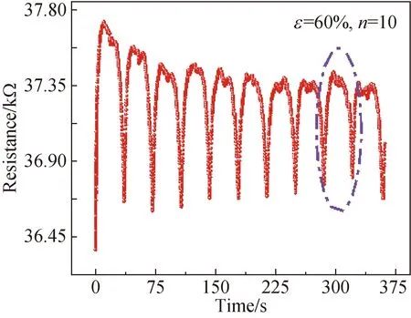
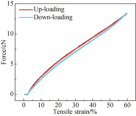
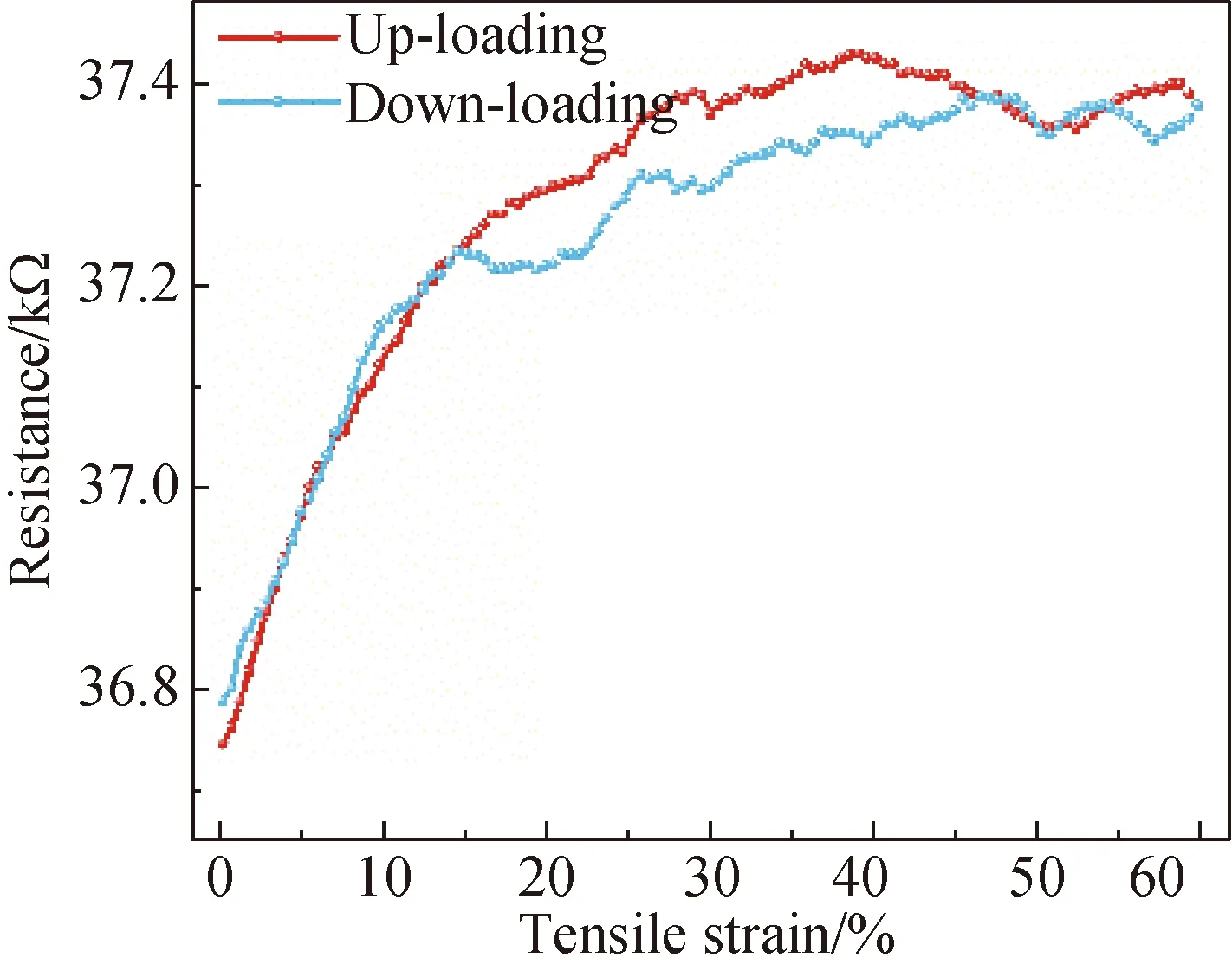
Cyclic loading tests were then conducted for sensing performance characterization. Figure 4 shows the electro-mechanical performance of the PPy-coated DCY sensor. Figure 4(a) illustrates the resistance change of the designed sensor against time for ten cycles in the cyclic loading test. It shows that the produced yarn sensors can respond positively to external periodic stimuli. The data in Figs. 4(b) and (c) are corresponding to the ninth cycle in Fig. 4(a). Calculated from the force-strain curve in Fig. 4(b), the mechanical hysteresis of the sensor is as low as 3.64%, indicating that the coating process basically does not affect the mechanical hysteresis performance of the DCY. However, the resistance-strain curve in Fig. 4(c) shows a significant resistance hysteresis loop, leading to significantly increased electro-mechanical hysteresis with a value as large as 14.3%.
(a)
(b)
(c)
Fig. 4 Electro-mechanical performance of the PPy-coated DCY sensor: (a) resistance-time curve; (b) force-strain curve; (c) resistance-strain curve
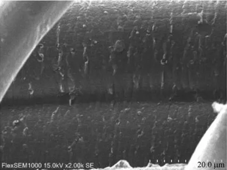
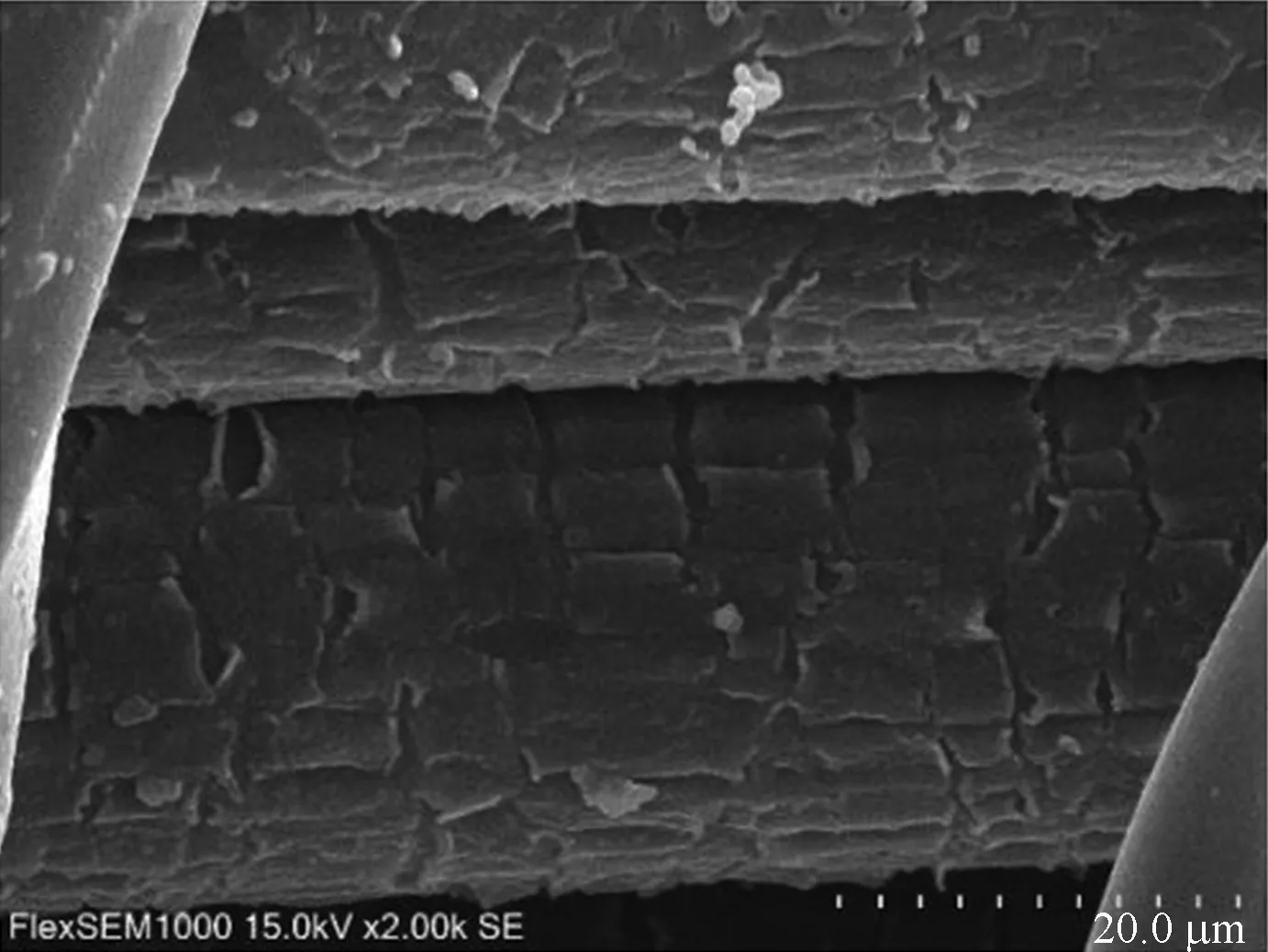
The sharp increment of electro-mechanical hysteresis indicates that the electro-mechanical behavior of the PPy-coated DCY sensor not only relies on the mechanical behavior of the DCY, but also depends on the micro-structural change of the PPy conductive layer coated on the yarn substrate. SEM observation was conducted after the PPy-coated DCY sensor was stretched with 60% strain for ten times. No obvious difference appears on the PPy-coated PA filaments after cyclic tensile tests as shown in Fig. 5(a), indicating a strong interfacial adhesion between the PPy conductive layer and the PA filaments. Hence, the conductive network on the PA filaments changes with the geometrical change of the PA filaments during the tensile test. Minor cracks occurred on the surface of the PU core after the tensile tests as shown in Fig. 5(b). The formation of cracks on the PU core demonstrates that the PU core is highly elastic and is elongated during the tensile test, while the PPy conductive layer cannot be stretched. Hence cracks are created. Thus, the mechanical hysteresis of the sensor mainly comes from the geometrical change of the PA filaments. However, the electro-mechanical hysteresis may primarily come from the geometrical change of the PA filaments and the unrecoverable cracks of the PPy layers on the PU core.

(a)
(b)
Fig. 5 SEM images of the PPy-coated DCY sensor after cyclic tensile tests: (a) PA filaments; (b) PU core
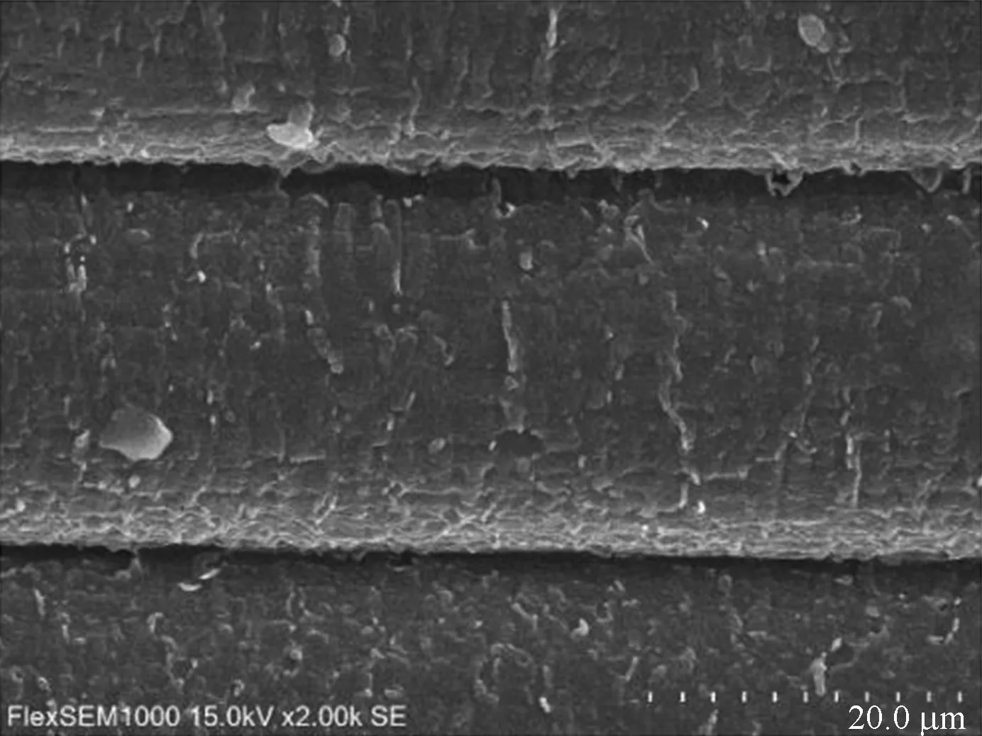
To further observe the micro-crack change of the PPy layer on the PU core, SEM images of the PPy-coated DCY sensors were obtained with different tensile strains of 0, 20%, 40% and 60%, as shown in Fig. 6. When the sensor is stretched to 20%, cracks are generated and become larger with increased strain. The cracks become the largest at 60% strain. The resistance-strain curve in Fig. 4(c) proves that, when the strain is less than 15%, there is almost no electro-mechanical hysteresis due to the structural integrity of the conductive layer. With the increase of strain, the cracks in the conductive layer will occur and increase due to the difference in the elasticity of the PPy layer and the PU core. More and more cracks lead to a significant increment in the resistance and large electro-mechanical hysteresis of the sensor.
(a)

(b)
(c)
(d)
Fig. 6 Morphological changes of conductive coating layer on PU core with different strains: (a) 0; (b) 20%; (c) 40%; (d) 60%
3 Conclusions
A yarn-based strain sensor was fabricated by coating conductive polymer, PPy, onto a DCY,i.e., PU/PA/PA, by in-situ polymerization. Surface morphology of the yarn-based strain sensors demonstrates that the PPy conductive particles are uniformly distributed on the surface of the PA multi-filaments as well as immersed into the PU surface due to the inherent pores in the DCY structure. The created strain sensor could accurately respond to external stimuli with a low mechanical hysteresis. However, the electro-mechanical hysteresis of the sensor is considerably large due to the geometrical change of the PA filaments as well as the micro-cracks of the PPy layer on the PU core, which is demonstrated through SEM observation of the samples with different strains.
杂志排行

Journal of Donghua University(English Edition)的其它文章
- Acoustic Performance of Green Composites for Chinese Traditional Percussion Drums
- Friction and Wear Behaviors of C/C-SiC Composites under Water Lubricated Conditions
- Performance Analysis of Cushioned Sport Soles with Plantar Pressure Test
- Existence Criterion of Three-Dimensional Regular Copper-1, 3, 5-Phenyltricarboxylate (Cu-BTC) Microparticles
- Combining User-Driven Social Marketing with System-Driven Personalized Recommendation for Student Finding
- Generative Adversarial Network with Separate Learning Rule for Image Generation