Measurement Method of Sound Impedance of Acoustic Coating in Water-tube without Back Layer
2019-01-09BAIZhenguoHUDongsenSHENQiYUXiaoli
BAI Zhen-guo,HU Dong-sen,SHEN Qi,YU Xiao-li
(1.National Key Laboratory on Ship Vibration&Noise,Wuxi 214082,China;2.China Ship Scientific Research Center,Wuxi 214082,China)
Abstract:To obtain the sound impedance of underwater acoustic coating,a sound impedance measurement method in water-tube without back layer is proposed.Formulas of the measurement method utilizing sound pressure of four hydrophones mounted in the water-tube are derived,and hence a measurement method is established.Then a numerical simulation of the measurement processing is carried out to validate the measurement method.And the measurement error caused by distance arrangement,mounting position and phase error of hydrophones is investigated by the simulation,after that,the modification of the measurement system is presented to lower the inferior limit frequency.
Key words:acoustic coating;sound impedance;measurement method;error analysis
0 Introduction
The acoustic coating aimed to reduce or isolate the sound transmission is widely used in underwater engineering.So it is very necessary to measure its acoustic characteristics accurately,then the relation between the sound behavior and design parameters can be determined.The most commonly used characteristic parameters include sound absorption coefficient,sound isolation coefficient and sound impedance,and so on.Among which,the sound absorption coefficient is commonly used.For sound absorption in the air,the sound absorption coefficient is available for most projects since the material such as porous foam often has much less impedance than the back wall.But it is not the case for underwater engineering for the impedance of the water almost matches the impedance of the steel wall,the sound absorption coefficient is not available to evaluate the sound reduction effect of the acoustic coating.Meanwhile,the impedance of the acoustic coating is sort of natural property which means it will not change with the application environment,and via which the sound absorption coefficient and sound isolation coefficient can be derived easily.For all the reasons presented above,obtaining the impedance of acoustic coating by measurement is taken into account more and more seriously recently.
To obtain the acoustic character,Chung and Blaser[1]developed Dual-sensor Transfer Function Method(DTFM)which makes wide-band measurement achievable.Cole[2]established the DTFM in water-tube to measure the impedance of acoustic coating,Schultz[3]analyzed the uncertainty of impedance measuring results via theoretical model and experiment.Li[4]employed 3 hydrophones to minish the measuring error caused by the hydrophone position,his experiments indicated that the position error would cause impedance error significantly.
Reseachers in China also gave some research on this topic.Zhu[5]set up a dual-hydrophone measurement system and measured the reflection coefficient of the acoustic coating,the error analysis was carried out as well.Lv[6]measured the sound absorption efficient with both DTFM and stationary wave method,the results at medium and high frequency measured by both methods matched each other well which validated the precision of the DTFM again.Zhou[7]analyzed the error behavior caused by hydrophone mounting position,hydrophone phase inconsistency and vibration of the tube via a numerical model.Three comprehensive dimensionless parameters were derived which can calibrate the measurement system.Based on all above,the measurement standard[8]was established to guide the measurement of impedance in water tube.To solve the interference problem caused by resonance of back pressurized air cavity which was designed to offer high pressure for the acoustic coating simulating the ocean pressurized environment,Pang[9]filled the back air cavity with sound absorption material such as asbestos coating,after doing this,the impedance was measured,the relation between impedance and sound absorption coefficient and sound isolation coefficient was derived which perfectly matched the directly measured sound absorption coefficient and sound isolation coefficient.This means the impedance is a better parameter which can offer more abundant information about the acoustic coating.
In the measurement system,a rigid back block clinging to the acoustic coating is set up which leads to the zero velocity of the back side of the acoustic coating.With a hydrophone on the block surface to measure the sound pressure,and with 2 hydrophones in the tube to measure the velocity and sound pressure of the front side of acoustic coating,then the transfer impedance of the acoustic coating can be obtained.By turning over and re-mounting the acoustic coating,the sound pressure and velocity were measured again,then the impedance of both sides of the acoustic coating can be determined.The accuracy of this method at low frequency depends on the rigidity of the back layer.While the rigidity condition can not be reached perfectly,the measured impedance will be incorrect at low frequency band.
A measurement method of sound impedance of acoustic coating in water-tube without back layer is proposed in this paper.Formulas of sound impedance of acoustic coating utilizing sound pressure of four hydrophones are derived.With this method,the end block condition is no longer regarded as an essential requirement,and the impedance at low frequency band can be measured precisely.
1 The impedance measurement method
1.1 Impedance calculation equation
A typical acoustic coating has two sides and its impedance is defined with following e-quation:
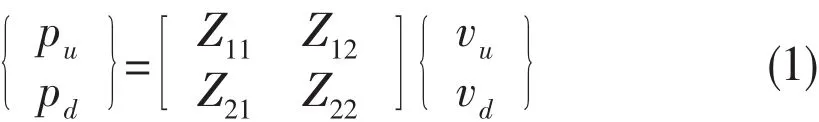
In which,pu,vu,pdand vddemonstrate the sound pressure and particle velocity on each side of the acoustic coating(see Fig.1),respectively;Z11,Z22are defined as input impedance at each side of the acoustic coating;Z12,Z21are defined as transfer impedance of two sides.As the parameters of Z11,Z12,Z21and Z22are regarded as unknown variables,formula(1)offers two equations with four unknown variables.So it is not sufficient to solve the impedance equations.
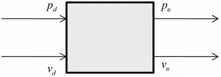
Fig.1 Diagram of sound pressure and particle velocity of acoustic coating
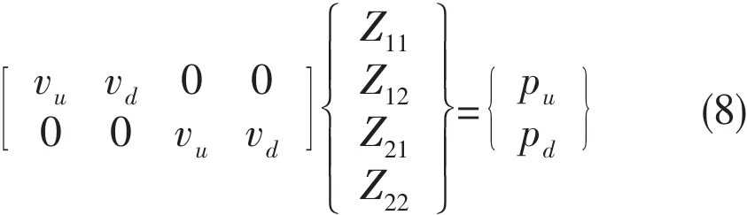
Since the impedance Z11,Z12,Z21and Z22is the natural character of the acoustic coating which will not change with the sound pressure on its surface,so if we obtain another equation with different pu,vu,pdand vd,we can have another equation as follows:

Eqs.(1)and(2)are simultaneously combined which give a set of equations:
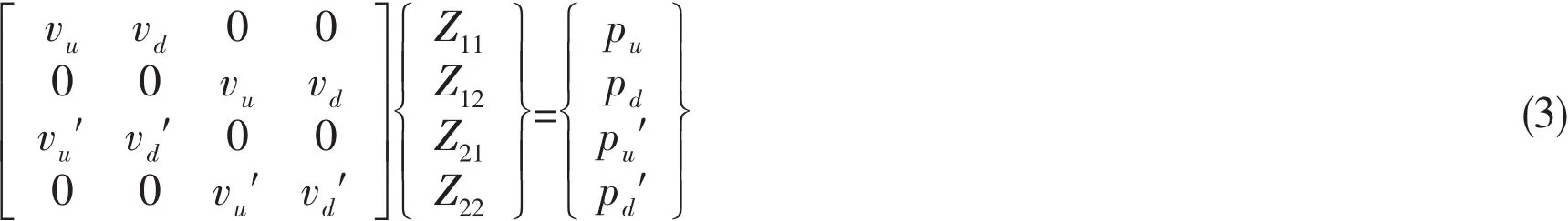
The impedance of acoustic coating expressed as Z11,Z12,Z21and Z22can be obtained by solving the set of Eq.(3).
1.2 Impedance measurement method
It is obvious that the key to obtain the sound impedance is to construct nonsingular equation coefficients matrix in Eq.(3),which means to set up two measurement cases to get two uncorrelated sets of pressure and particle velocity.Then the set of Eq.(3)can be derived.
But for the water tube measurement system,it is hard to measure the acoustic coating surface pressure and velocity due to various causes,such as the high pressure sealing problem of the tube,and the mounting of the accelerator on the soft surface of the acoustic coating,and so on.Some realistic arrangement is to measure the sound pressure and particle velocity indirectly,which can be implemented by installing two hydrophones in the water at each side of the acoustic coating to get the pressure and velocity with transfer function in the 1-D wave guide water tube.The diagram of the measurement system is showed in Fig.2.
The hydrophones collect the sound pressure on the relevant position,then the sound pressure and particle velocity of two sides of the acoustic coating can be obtained by the following formulas:
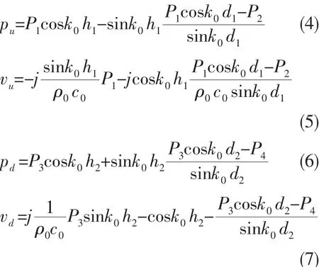
In which,the distance variables d1,d2,h1and h2are defined in Fig.2,k0=ω/c0,c0is the sound speed in the water tube which is 1 500 m/s;ρ0is the density of the water which is 1 000 kg/m3;P1~P4are the sound pressure of the No.1#-No.4#hydrophones.We can get two equations by substituting formulas(4)~(7)into Eq.(2):
Then we change the liquid column of the upper water in the tube by adding some water in the tube,repeat the measurement process again,and we obtain two other equations as follows:
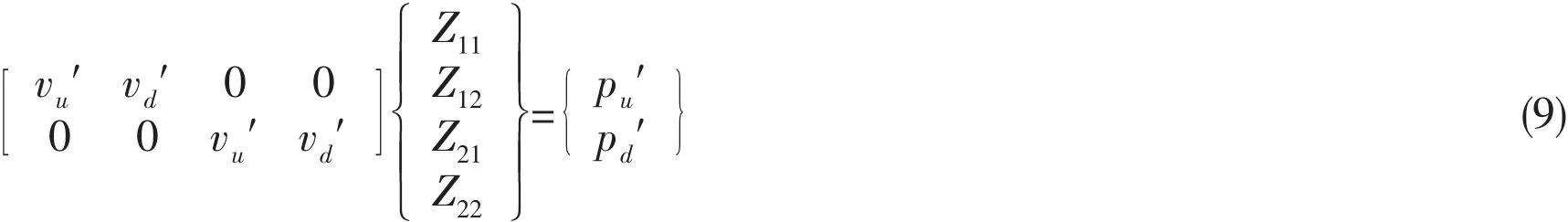
Simultaneously combining set of Eqs.(8)and(9),set of Eq.(3)is constructed successfully by solving the set of equations,we can get the impedance Z11,Z12,Z21and Z22.
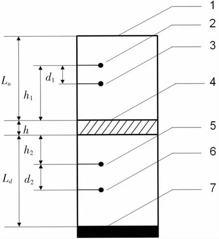
Fig.2 Diagram of water tube measurement system
2 Numerical simulation of the measurement
To validate the accuracy of the measurement method presented above,a numerical model is demonstrated in this chapter.The basic assumption of the numerical model includes:the acoustic coating is homogenous which means only the longitudinal wave is considered,the sound speed and density are known which means the impedance of the acoustic coating can be calculated directly,the vibration velocity of the underwater sound transducer(shown as 7#in Fig.2)is known which means we can obtain the sound pressure in the water tube by giving the end condition.
By following the measurement method in section 1.2,sound pressure of each hydrophone is calculated twice for two different cases,which are used as input parameters for Eqs.(4)-(7).After obtaining the sound pressure and particle velocity of the acoustic coating surface,Eq.(8)and Eq.(9)can be constructed,and the impedance could be obtained by solving the set of equations.
The measurement method can be validated by comparing the impedance obtained by the measurement method with the impedance calculated directly by the sound speed and density.
2.1 Analytical model of sound pressure in the tube
For the measurement system showed in Fig.2,the sound pressure and velocity at any position in the upper water column can be calculated with the sound pressure and velocity on the upper surface of the water column:

In which,pT,vTare sound pressure and particle velocity at the interface between water and air.Since the medium above this interface is air which can be regarded as vacuum,so the interface can be seen as soft boundary for the water column.Thus,we have pT=0;And the matrixrepresents the transfer matrix of the upper end of water and field point in the water.
The transfer matrix in the uniform medium for 1-D water tube can be expressed as the following formula:

Thus,the transfer matrix of the interface to the field point for the field point in the upper water column is represented as follows:
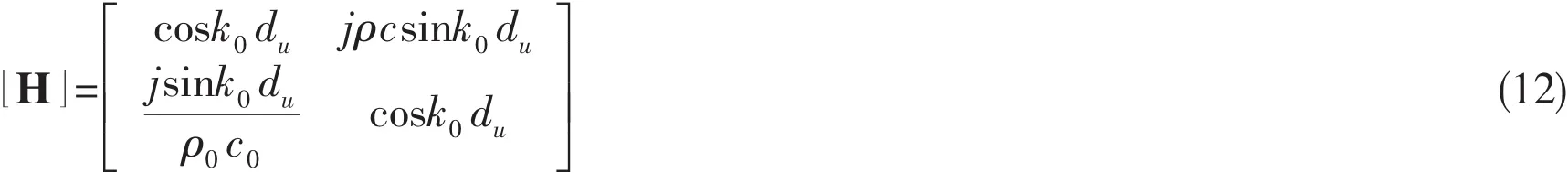
In which,dudenotes the distance between the random field point in the upper water column and the upper interface.As for the random field point in the lower water column,the transfer matrix of the interface to the field point is:
In which,d denotes the distance between the field point in the lower water column and the lower surface of the acoustic coating;h denotes the thickness of the acoustic coating;Ludenotes the length of the upper water column;ρ,c denote the density and the sound speed of the acoustic coating,respectively.We have d=h2for the hydrophone No.3#,and d=h2+d2for the hydrophone No.4#,and d=Ldfor the sound transducer.
Substituting formula(13)into formula(10),the following equation is deduced:

2.2 Numerical validation of the measurement method
To validate the measurement method,a numerical simulation is carried out in this section.The simulation parameters are given in Tab.1.
Firstly,we use the parameters to get the sound pressure of the four hydrophones.Then we consider the calculated sound pressure as measuring sound pressure,substitute the pressure data into formulas in section 1.2,and the impedance can be calculated.By comparing the impedance in section 1.2 and the impedance utilizing acoustic coating density and sound speed,the effectiveness and accuracy can be validated.
Since the commonly used water-tube in laboratory has a diameter of Φ 120 mm,its higher cut-off frequency is:Hz,thus the frequency band in this paper becomes:10 Hz~7 kHz.

Tab.1 Simulation parameters
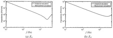
Fig.3 Impedance with analytical calculation and measurement simulation
The impedance curves of the acoustic coating given by direct analytical method and measurement method are presented and compared in Fig.3.It is showed that the impedance(input impedance and transfer impedance included)obtained by the two methods matches well,the two curves coincide with each other exactly,which means the measurement method we proposed works well.Thus the accuracy of sound impedance obtained by the measurement method is proven.
2.3 Error analysis of the measurement method
To analyze the error characteristic of the measurement method,further numerical simulation is carried out to calculate and analyze the error caused by the distance of hydrophones and the mounting position error and some other factors.
2.3.1 Error caused by distance of hydrophones
The influence of the distance of hydrophones is presented in Fig.4 and Fig.5,which is calculated based on the parameters of d1=0.2 m,d2=1 m and d1=1 m,d2=0.2 m while the other parameters remain as Tab.1.It is showed that the trend and the aptitude of the measuring impedance curve are negligibly affected by the distance of hydrophones,other than some unwanted peaks emerge with the distance changes.The figures reveal the peaks exist at the frequency 750 Hz and its higher order frequency,which are determined by the zero point of formula sink0d1,sink0d2in Eqs.(4)-(7),which means the peaks are related to the singularity of measured sound pressure which is determined by the distance of d1,d2,it has nothing to do with the distance of the upper hydrophone and the lower hydrophone.
If we take the background noise of the water tube into account,the singularity of the sound pressure will not be highlighted in reality,thus the unwanted peak of the impedance curve will recede or even vanish.Anyhow,the unwanted peaks can be avoided with 3 hydrophones in both water columns,for different distance makes different peaks,and by combining different curves with different peaks we can get a smooth curve.Or even more,because the frequency of peaks can be predicted exactly,the peaks can be erased artificially when processing the measuring results.
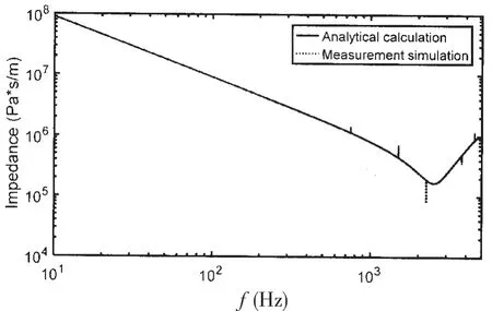
Fig.4 Influence of distance between hydrophones of the upper tube(Z11)
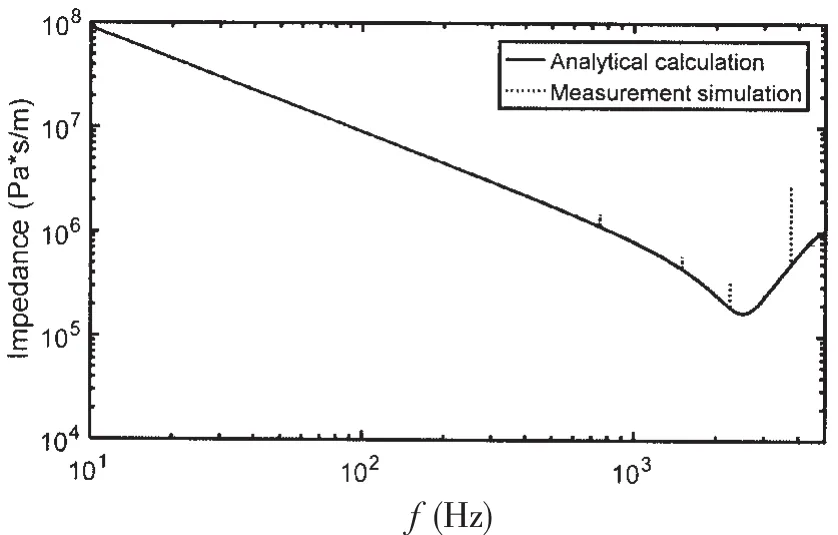
Fig.5 Influence of distance between hydrophones of the lower tube(Z11)
2.3.2 Error caused by mounting position of hydrophones
When the measurement is carried out in the laboratory,the mounting position of the hydrophones will deviate from where it should locate.The deviation may reach 2-6 mm which will influence the measuring impedance.The error of the impedance is given by Fig.6 and Fig.7.
In Fig.6,the deviation of hydrophone No.1#is+6 mm and the deviation of hydrophone No.2#is-6 mm;while in Fig.7 the deviation of hydrophone No.1#is+6 mm and the deviation of hydrophone No.3#is-6mm.It is showed that the position deviation of the hydrophones af-fects the impedance at high frequency above 4 000 Hz,there comes two obvious abnormal peaks differ from the real impedance curve.And for the low frequency,the error of impedance amplitude caused by the mounting deviation reaches about 33%(which are 9.1e7 Pa*s/m and 6.1e7 Pa*s/m,respectively)at 10 Hz and 20%(which are 4.5e6 Pa*s/m and 3.6e6 Pa*s/m,respectively)at 200 Hz.It is to say,the deviation of the hydrophone can lead to an error of about 3 dB at 10 Hz and 1 dB at 200 Hz for sound absorption and transmission.To avoid this error,it is strongly suggested to calibrate the water-tube system with a water layer which can be predicted by theory.
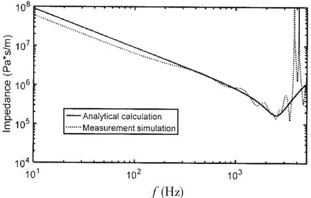
Fig.6 Influence of mounting error of 1#and 2#hydrophones(Z11)
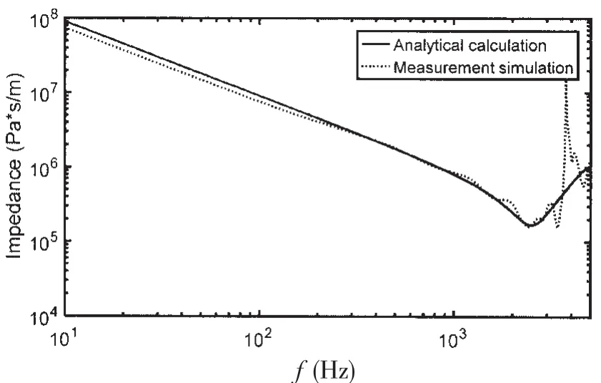
Fig.7 Influence of mounting error of 1#and 3#hydrophones(Z11)
2.3.3 Error caused by phase bias of hydrophones
The phase of the hydrophone must have been calibrated before the measurement is carried out,but the phase calibration accuracy is often limited to 2°.This is okay for the measurement at high frequency,but it will bring considerable deflection to the impedance measurement at low frequency band.
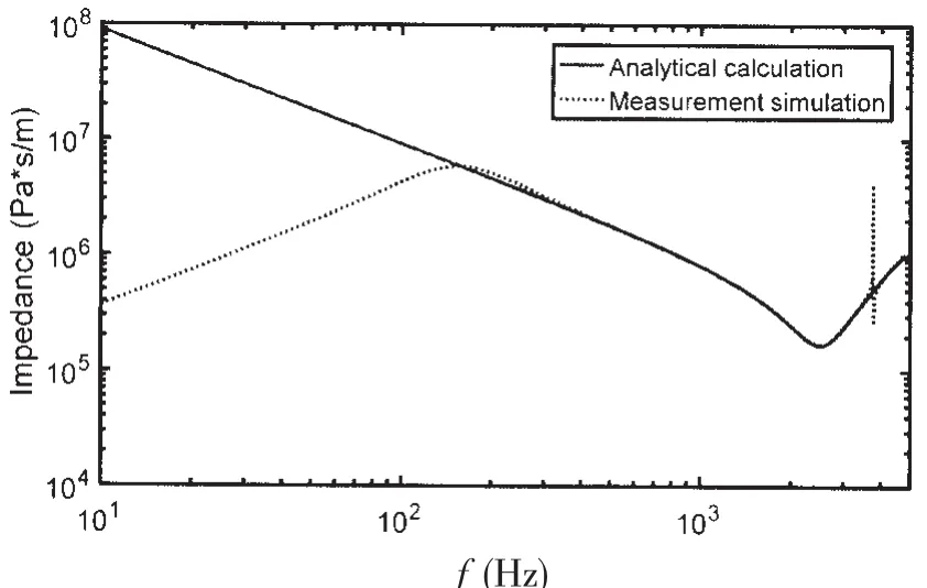
Fig.8 Influence of phase error of 1#hydrophone(Z11)
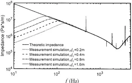
Fig.9 Influence of distance of 1#and 2#hydrophones with phase error for 1#hydrophone(Z11)
The error caused by hydrophone phase is presented by Fig.8.In Fig.8,the phase error of hydrophone No.1#is assigned to be 2 degrees while the other hydrophones are in good condition without phase error.It is showed that the phase error influences the impedance mainly at the low frequency below 200 Hz,the lower the frequency is,the bigger the deflection shows.The reason for this phenomenon is that the measurement depends on the transfer function of the hydrophones No.1#and No.2#.And the distance between these two hydrophones is only 20 cm which generates phase difference of 4.8 degrees at 100 Hz.So the phase error of hydrophone No.1#will bring 40%phase error of the measuring phase of the transfer function,it is a huge error for the measurement system,so the measuring impedance at low frequency varies a lot from the real impedance as shown in Fig.8.
By Fig.8,it is known that the hydrophone phase error mainly impacts the low frequency impedance,to reduce this error,we can lengthen the distance of the hydrophones.With the same phase error of hydrophone No.1#,the distance of hydrophones No.1#and No.2#affects the measuring impedance,which is given in Fig.9.It is shown that the lower limit frequency of the measurement descends as the distance of hydrophones No.1#and No.2#lengthens.When the distance reaches 1.6m,the lower effective measurement frequency band can reach to 60 Hz.So with actual measurement system,it is strongly suggested that three or more hydrophones with varied distance to the acoustic coating should be set up in each water column.By using the adjacent hydrophones,one can erase the line spectrum at high frequency band,and by using the distant hydrophones one can lower the effective frequency of measurring impedance.
3 Conclusions
A measurement method of acoustic coating impedance in water-tube is presented which is independent to the rigid back layer of the acoustic coating.The formulas of the method are deduced by using the transfer function of the sound propagating in 1-D wave guide.A numerical simulation approach is proposed to validate the measurement method and the measurement error caused by various factors such as mounting position error and phase error of hydrophones is analyzed.The main conclusions are listed as follows:
(1)The method measuring the impedance of acoustic coating by solving the set of transfer impedance equations of sound coating twice with different ending condition is validated by numerical simulation.The measurement has no back layer for the acoustic coating which avoids incorrectness at low frequency,by this method one can measure the impedance at any frequency precisely and theoretically;
(2)The distance of the hydrophones makes unwanted line spectrums to the impedance curve.To avoid the singularity,it is suggested to set up more hydrophones to configure more distance cases to obtain multiple impedance curves,by combining the different impedance curves,the line spectrums can be erased by data processing;
(3)The mounting position of the hydrophones influences the impedance at high frequency band instead of the low frequency band which is not the aiming frequency of this paper;
(4)The phase error of the hydrophones can lead to considerable deviation of the measuring impedance result at low frequency.Setting up some more hydrophones far away from the coating is suggested,which can lower the valid measuring frequency.
杂志排行

船舶力学的其它文章
- Dynamic Stability of Liquefied Cargo Ship in Waves
- Investigation on Time Domain Motions for Ship and Floating Structure and Coupled with Nonlinear Sloshing
- Overset Simulations of Submarine’s Emergency Surfacing Maneuvering in Calm Water and Regular Waves
- A Revised Method for Predicting Added Waves Resistance Based on Comparison of Theoretical and Empirical Results for VLCC Hull Forms
- 3D Nonlinear Hydroelastic Response and Load Prediction of A Large Bulk Carrier in Time Domain
- Strength Characteristics of Maraging Steel Spherical Pressure Hulls for Deep Manned Submersibles