3D Nonlinear Hydroelastic Response and Load Prediction of A Large Bulk Carrier in Time Domain
2019-01-09YANGPengGUXuekangDINGJun
YANG Peng,GU Xue-kang,DING Jun
(1.Wuhan Second Ship Design and Research Institute,Wuhan 430205,China;2.China Ship Scientific Research Center,Wuxi 214082,China)
Abstract:Two time domain three-dimensional hydroelastic analysis methods of ship advancing in waves are presented.One is based on the complex time domain Green’s function in the whole fluid region(the TDGF method).The other is the Inner and Outer Regions Matching method(the IORM method),where the Rankine source method is used in the inner fluid region between the ship hull and an imaginary boundary surrounding the ship;while the time domain Green’s function is used in the outer region outside the imaginary boundary.The hydroelastic responses of a 205 000 DWT,295 m long bulk carrier in waves are calculated for two forward speeds of 0 and 14.8 kns.The results predicted by the TDGF method and the IORM method are presented and compared with each other.The forward speed effect is also discussed.The wave basin tests of the ship model with multi-segments and elastic backbones were carried out.The resonant frequencies and the hydrodynamic damping coefficients corresponding to the two-node vertical bending modes,and the motions and vertical bending moments in regular and irregular waves were measured.The time domain numerical predictions are illustrated in this paper and compared with the model test results and the predictions of the frequency domain method by employing the code ‘THAFTS’.Good agreements are achieved in the comparison.This exhibits that the two three-dimensional hydroelastic analysis methods in time domain presented in this paper and the corresponding codes can be used to reasonably estimate the hydroelastic responses of large ships in waves.Furthermore,the influences of the nonlinear Froude-Krylov force and hydrostatic restoring force on instantaneous wetted surface to hydroelastic response and loads are investigated.
Key words:hydroelasticity;time domain;Green’s function;Rankine source;large bulk carrier
0 Introduction
During the past two decades,the hydroelastic effects were recognized to be more and more important in wave load estimations and structural safety assessments of large ships due to the development towards larger and larger sizes and reduction of hull-girder natural frequencies.Several two-and three-dimensional hydroelastic analysis methods were well developed to predict the springing and whipping responses of large ships travelling in rough seas[1-6].Among these methods most are based on the frequency domain analyses involving the calculations of the pulsating source,translating-pulsating source,or the Rankine source Green’s functions.The time domain hydroelastic analysis methods were also investigated and applied[7],however far from enough.Time domain analysis is important especially when slam induced whipping responses are of great concern.
Wu and Cui(2009)[2]summarized the progress of 3D linear,nonlinear hydroelasticity and experiment technology.Hirdaris and Temarel(2009)[4]discussed the application tendency on fully nonlinear fluid-structure interaction technology of 2D and 3D hydroelasticity,including CFD method.The theories and applications of hydroelasticity in marine structures including the linear and non-linear springing and whipping responses of large ships advancing in waves were discussed in several conference or workshop proceedings and the special issues of journals,for example[2-5].Although many references studied the hydrodynamic actions and motions of ships and floating bodies in time domain by complex three-dimensional time domain Green’s function(TDGF)[8-11]or Rankine method[12-16],only Wang[7]and Wang&Wu[17]formulated the three-dimensional time-domain hydroelasticity theory of ships based on the TDGF method.The theory and the numerical method were validated by comparison of the predictions and the test results of an elastic ship model.Even though the investigation on three-dimensional time domain hydroelastic analysis of a ship responding to waves with forward speed has been quite limited.The work presented in this paper sets one step forward after the previous work of Wang&Wu[17]based on TDGF.Meanwhile,a time domain inner and outer regions matching method(the IORM method)is also presented,where the Rankine source method is used in the inner fluid region between the ship hull and an imaginary boundary surrounding the ship;while the time domain Green’s function is used in the outer region outside the imaginary boundary.This method is especially useful when the ship has large bow or stern flare.The numerical methods and the corresponding codes are verified by the comparisons of the predictions and the model test results of a 205 000 DWT bulk carrier.
1 Mathematical formulation
1.1 Time domain Green’s function method(TDGF)
In this paper,an equilibrium set of axes oxyz is defined to describe the motions of the fluid and the structure.It moves with forward speed U0in ox,the longitudinal direction of the ship,remaining oy pointing to port and oz pointing vertically up.The origin o is located on the intersection of the vertical line passing through the gravity center of the ship and the calm water surface.
The boundary integral equation of unsteady velocity potential φ( p, )t in time domain is
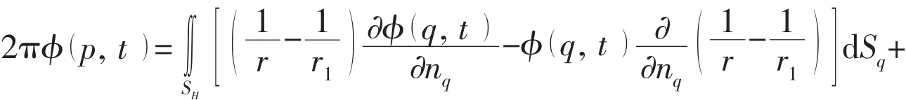
The t0=0 for radiation potential,and t0→-∞ for diffraction potential.Where p( ξ,η, )ζ and q( x,y, )z are the field point and source point,respectively.SHand Γ are respectively the wetted surface of the body and the line intersection of still water plane and the wetted surface of the ship.nqis the normal unit vector of the wetted surface at the source point,pointing into the ship hull.U0is the forward speed.is the complex three-dimensional time domain Green’s function,represented as

1.2 Inner and outer regions matching method(IORM)
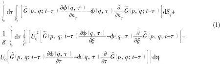
The sketch of the inner and outer regions matching method is shown in Fig.1.When Rankine source is used in boundary element method to describe the fluid actions,the free surface and the body’s wetted surface all need to be meshed in panels.To satisfy the radiation condition in far field,a control surface SCsurrounding the body’s wetted surface SHis introduced as shown in Fig.1.Inside the enclosure of SH,SCand the free surface SFis the inner fluid region ΩI,where the Rankine sources are distributed on the whole enclosed surface with the unit normal vectors pointing out of the inner fluid region.Outside this enclosure in the fluid region ΩII,the TDGF method is used.The velocity potential at any position in the two regions is expressed as
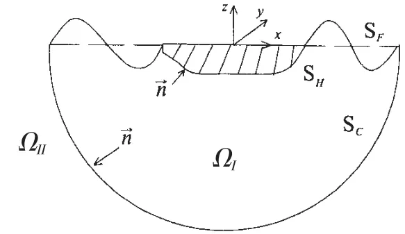
Fig.1 Sketch of the inner and outer regions matching method
where φ0is velocity potential of incident wave.
The boundary integral equation of Rankine source method in the inner fluid region ΩIis

The potential φIIin outer fluid region ΩIIcan be expressed by Eq.(1).The boundary conditions of the two potentials and their normal derivatives on the control surface are

1.3 Hydrodynamic coefficients and equations of motion
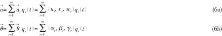
It is assumed that the motions and distortions of the floating structure in waves are small,and the dynamic responses of whole fluid-structure system are linear.According to Ref.[18],the translational displacementand rotationat any position of the ship structure may be expressed as an aggregate of displacements in its principal modes:
The radiation potential φr(p, )t of the rth mode could be decomposed into two transient terms and a memory term.If introducing new expression

And

where ψ1r(p)and ψ2r(p )are transient terms,and ψ2r(p )is relative to forward speed,χr(p, t)is memory term;δ(t)and H(t)are the Dirac impulse function and the step function,respectively.Then

According to Ref.[19],the generalized boundary condition of radiation potential on the body’s wetted surface may be represented as

or

where the expressions of arand brare defined by Wu(1984)[19].

or br=U0mr,denoting mr=n3θyr-n2θzr.
The equations of motion in time domain may be derived and expressed in the form:

where{q (t )}is the principle coordinate.[a],[b]and[c ]are the inertia mass matrix,damping matrix and elastic restoring force matrix,respectively.[C ]is the restoring force in still water.{F}is the generalized wave exciting force.{R′}is the time variant concentrated force,such as mooring force.[A]and[K ]are the added mass and impulse response function respectively.[B]and[C′]are respectively the added damping and restoring force induced by forward speed effect,which will vanish for zero speed.The elements of these matrices are as follows:
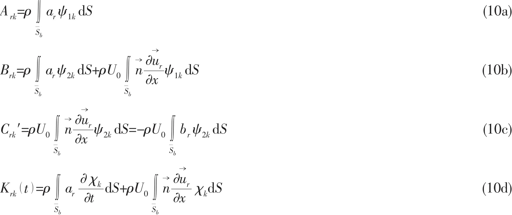
where ρ is fluid density.
2 Model test of a bulk carrier
A bulk carrier is taken as an example in this paper for time domain analysis of wave and structural responses.The dead weight of the ship is 205 000 ton.The model test of the ship in full loading condition was carried out at the wave basin of CSSRC.The segmented model was of the scale 1:50,made of FRP(Fiber Reinforce Plastic)with ten segments and elastic backbone,as shown in Fig.2.The 10 segments were cut at stations Nos.2,4,6,8,10(-50 mm),12,14,16 and 18.
To examine the loads and the structural responses of this ship in waves,the geometric similarity of wetted surface,the hydrodynamic similarity of global motions,and the similarities of mass and stiffness distributions of the hull girder along the length,together with the radius of longitudinal gyration were satisfied.The principal particulars of the ship and the model are listed in Tab.1.The resonant frequency of two-node bending mode in calm water was calculated by employing the software THAFTS[19]of frequency domain three-dimensional hydroelastic analysis,developed by CSSRC based on the theory of Ref.[19].
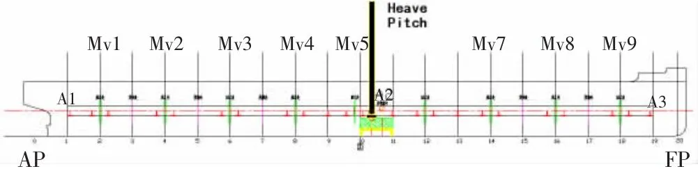
Fig.2 Measured points of motion and bending moment
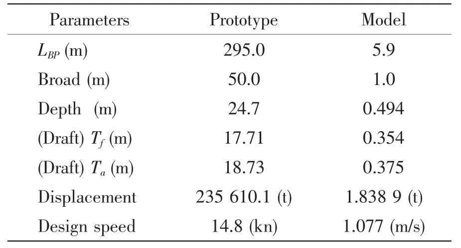
Tab.1 Principal particulars of the bulk carrier
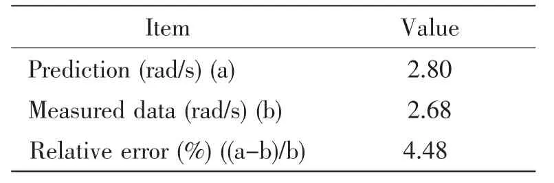
The resonant frequency and damping ratio of the two-node bending mode of the model in calm water without speed were measured in hammering test.The results and that obtained by numerical predictions are compared in Tab.2.The relative error between the two results of the twonode frequency is about 4.48%.And the damping ratio from the model test is 4.55%.The structural damping ratio is given as 1%in the following numerical simulation.
The 3D FEM model of the ship hull has 178 157 shell elements,124 032 beam elements and 302 189 elements in total.The symmetry property of the ship allows the hydroelastic responses be numerically predicted by half of the wetted surface constituted by the mesh of 794 panels shown in Fig.3(a).And the whole hydrodynamic model has 964 panels including wetted surface and the elements above waterline.This is used in the predictions by the TDGF method.
Tab.2 Predicted and measured two-node frequencies of the model(full scale)
In the predictions by the IORM method,a control surface is introduced,which is the combination of a circular cylinder of the radius 450 m and a flat bottom.Similarly,the mesh of half boundary of the inner fluid region Ω1is required that consists of 1 200 panels on the semi-circle free surface and 672 panels on the half control surface,as shown in Fig.3(b).
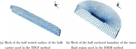
Fig.3 Mesh used in the hydroelastic analysis of the bulk carrier
3 Structural modes and resonant frequencies
The 3D FEM model of the bulk carrier in vacuum is used to calculate the dry global modes and corresponding natural frequencies.Fig.4 shows the two-node vertical bending,onenode torsion,two-node horizontal bending,and three-node vertical bending with full scale natural frequencies from 3.768 rad/s to 7.632 rad/s.
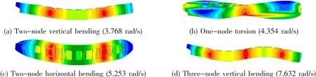
Fig.4 Dry modal shapes of the bulk carrier
When the ship is floating on water surface and encountering sinusoidal excitations,its structural dynamic responses will contain the contributions of different modes as shown in Eq.(6).At certain excitation frequencies,the structural resonances,each in one of the principal modes,may occur.Due to the fluid-structure interactions the hydrodynamic effect appears as the added mass,leading to each of the resonant frequencies lower than one of the natural frequencies of the ship in vacuum corresponding to the same mode,as shown in Tab.3.Obviously,in designing the ship structure it is important to avoid the resonant frequencies lying in the major frequency regions of engine and machinery excitations.The smallest resonant frequency of the bulk carrier among all structural distortion modes corresponds to the two-node vertical bending mode,which is 2.8 rad/s.Although the frequency region of major wave energy in the sea is usually lower than 1.5 rad/s,the high forward speed of the ship may increase the encounter wave frequency and reach as high as the resonant frequency of the two-node vertical bending mode,resulting in the springing responses.
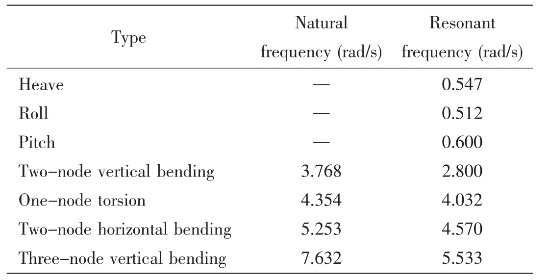
Tab.3 Natural frequencies and resonant frequencies
4 Motions and wave loads
The motions and wave loads of the bulk carrier are predicted by both the TDGF and IORM methods in this chapter.
4.1 Zero forward speed
Fig.5 shows the impulse response function,the transfer functions of motions and wave loads of the ship at zero speed predicted by two time-domain methods TDGF and IORM described in this paper,and the 3D frequency domain hydroelastic analysis method(THAFTS).The results of impulse response function of heave calculated by TDGF and IORM in Fig.5(a)are coincident.When the non-dimensional time is greater than 4.0,the impulse response function tends to zero.The transfer functions of heave,pitch and vertical bending moment predicted by the three methods in Fig.5(b-d)are also close to each other.
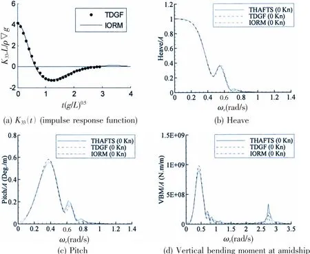
Fig.5 Transfer functions of rigid body motions and vertical bending moment of the bulk carrier(head sea,zero speed)
4.2 Non-zero forward speed
Fig.6 shows the comparisons of the predicted impulse response function,the transfer functions of motions and wave load of the ship advancing in waves at 14.8 kns by employing the three methods as mentioned in last section,as well as the test results.The two time-domain methods provided the results of impulse response function of heave with good agreement,as shown in Fig.6(a).The impulse response function approaches zero when the non-dimensional time is larger than 3.0,earlier than the zero speed case.The impulse response function of heave predicted by TDGF method slightly fluctuates when the non-dimensional time is greater than 1.0.The reason needs further investigation.The numerical and experimental results of heave and pitch at 14.8 kns in Fig.6(b,c),show similar tendency except in the encounter frequency region from 0.5 rad/s to 0.6 rad/s.This is the frequency region of heave and pitch resonances.Predictions by any means in this region are usually influenced by damping effect,including the viscous damping.The latter has been neglected in the present heave and pitch predictions.It seems that the heave motion predicted by IROM provides better agreement with the test result.The frequency domain approach underestimates the heave motion and the TDGF method overestimates the heave motion.Furthermore,the numerical and experimental results of vertical bending moment shown in Fig.6(d)also exhibit the same tendency.At the vicinity marked by S1 where the ratio of wave length to ship length is about 1.0,the predictions of TDGF and IORM and the experimental results for the vertical bending moment all drop down,while the prediction of the frequency domain method does not.
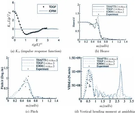
Fig.6 Transfer functions of rigid motions and vertical bending moment of the bulk carrier(head sea,14.8 kns)
To investigate the influence of nonlinear Froude-Krylov force and hydrostatic restoring force due to instantaneous wetted surface and large motion on motion and load predictions,the time history of vertical bending moment amidships induced by P-M irregular incident wave of significant height 4 m and zero-crossing period 7 s shown in Fig.7(a)and(b)are calculated.It is to integrate pressure over the instantaneous wetted surface,and only the undisturbed incident wave and hydrostatic pressure taken into account[20].The time length is 3 hours,and the time series of wave and vertical bending moment at amidship are shown in Fig.7(b)and(c).The linear and nonlinear results are compared in Fig.7(c).Apparently,for this ship style without large flare,the predicted time curves are almost consistent between linear and nonlinear cases implying that the influence of instantaneous wetted surface and ship motions on wave loadings is negligible.
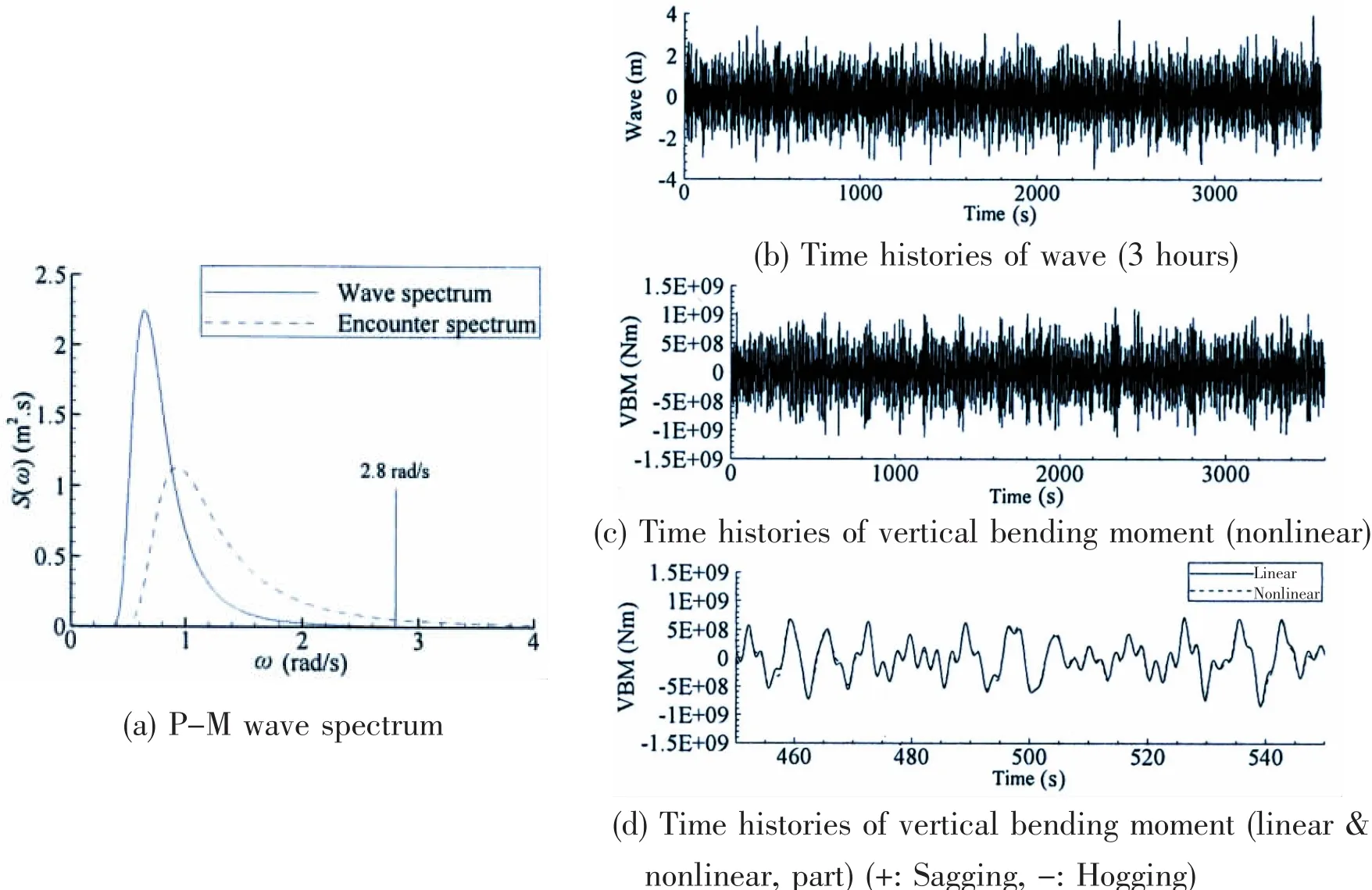
Fig.7 Vertical bending moment at amidship(head sea,Hs=4 m,Tz=7 s)
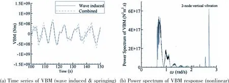
Fig.8 Time histories of VBM(head sea,Hs=4 m,Tz=7 s)
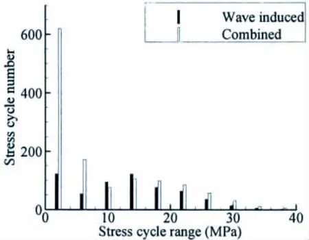
Fig.9 Stress range distribution principles of upper deck
The vertical bending moments induced by wave and springing are shown in Fig.8(a)respectively,and the combined bending moment including the wave induced component(low frequency)and the springing induced component(high frequency).The frequency of wave induced VBM is less than 1.5 rad/s.The springing occurred at high frequency of 2.8 rad/s,which has apparently increases the cycles of vertical bending moment and would induce serious structural fatigue damage.The stress cycle ranges distribution principles of one typical upper deck point with sectional module of 55.4 m4are shown in Fig.9 by rain-flow counting method.And the stress cycle numbers of combined VBM are larger than wave induced case.On the other side,the significant values of wave induced and combined vertical bending moment are shown in Tab.4.The latter is about 5%larger than the former,which reflects that the springing also increases the wave loading of ships,and sagging VBM is nearly equal to hogging VBM.Then the smoothed power spectrum of vertical bending moment response is shown in Fig.8(b),and there are obvious high frequency responses of VBM which are near 2-node vertical bending modal.Furthermore,for the VBM responses of linear and nonlinear are almost consistent,see Fig.7(d)and Tab.4,it is concluded that the high frequency responses are induced by linear springing.And the considerable wave energy around 2-node vertical bending modal(2.8 rad/s)excites the linear springing,see Fig.7(a).
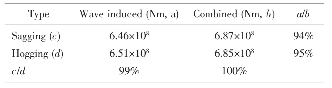
Tab.4 Significant values of vertical bending moment
5 Conclusions
Two time domain 3D hydroelastic analysis methods are proposed in this paper.These are the Time Domain Green’s Function(TDGF)method and the Inner and Outer Regions Matching(IORM)method.The numerical examples of a 205 000 DWT bulk carrier responding to waves at forward speeds 0 and 14.8 kns are exhibited,and compared with the predictions by the frequency domain 3D hydroelastic analysis method and the model test results.The influences of forward speed,the instantaneous wetted surface on the motions and vertical bending moments are roughly investigated at the present stage.Some important conclusions are as follows.
(1)In case of zero forward speed,the predictions of using TDGF method,IORM method and the frequency domain method are quite close to each other.
(2)When the ship is advancing in waves with forward speed 14.8 kns,the transfer functions of heave and pitch predicted by the TDGF and IORM methods are more consistent with the test results than predicted by the frequency domain method.When the wave length is nearly the same as the ship length,the test result of transfer function of the amidship vertical bending moment drops down.The numerical results provided by the TDGF and IORM methods may properly predict this phenomenon.
(3)The time domain TDGF and IORM methods may handle the instantaneous wetted surface effect in wave load predictions,showing the nonlinear phenomenon in high waves.It is a pity that there is a little nonlinear response of the bulk carrier here.But it is necessary to study the hydroelastic response of large ships during loading investigation.The springing will enlarge the loading value and cycles with an apparent level.
(4)The time domain hydroelastic analysis methods presented in this paper allow for fur-ther development in estimation of non-linear responses of high speed ships and description of slamming induced whipping phenomena.
Acknowledgements
The study,partly reported in this paper,is supported by the National Basic Research Program of China(No.2013CB036100).The authors thank the colleagues of the Structure Division of CSSRC for performing the model test.
杂志排行

船舶力学的其它文章
- Dynamic Stability of Liquefied Cargo Ship in Waves
- Investigation on Time Domain Motions for Ship and Floating Structure and Coupled with Nonlinear Sloshing
- Overset Simulations of Submarine’s Emergency Surfacing Maneuvering in Calm Water and Regular Waves
- A Revised Method for Predicting Added Waves Resistance Based on Comparison of Theoretical and Empirical Results for VLCC Hull Forms
- Strength Characteristics of Maraging Steel Spherical Pressure Hulls for Deep Manned Submersibles
- Research on Stress Intensity Factors for the Deflected Crack of CTS Specimen