Overset Simulations of Submarine’s Emergency Surfacing Maneuvering in Calm Water and Regular Waves
2019-01-09ZHOUGuangliOUYongpengGAOXiaopengLIURuijie
ZHOU Guang-li,OU Yong-peng,GAO Xiao-peng,LIU Rui-jie
(1.Department of Naval Architecture,Naval University of Engineering,Wuhan 430033,China;2.Naval Academy,Beijing 100161,China)
Abstract:A numerical method combined with dynamic overset technique is introduced to predict the strongly nonlinear motion and instantaneous flow field during submarine’s emergency surfacing.Simulations of surfacing maneuvering for a buoyantly rising submarine in calm water and waves were carried out based on Reynolds Averaged Navier-Stokes(RANS)equations and Volume of Fluid(VOF)model.Validation for numerical wave-making was performed with satisfactory results before these simulations.Reasonable motion characteristics and flow physics around the submarine demonstrate that the current method is feasible and potential for direct computation of submarine’s emergency surfacing in severe environments.
Key words:submarine;emergency surfacing;CFD;overset grids;wave
0 Introduction
For a submarine sailing underwater,it is very dangerous to experience on-board fires,flooding or rudder jamming accidents.Emergency surfacing is the most common maneuver to cope with these situations through high-pressure air blowing.To insure navigation security,accurate prediction of submarine’s hydrodynamic performance and motion characteristics during emergency surfacing has significant engineering value.
The conventional methods to forecast submarine’s six degrees of freedom(6DOF)motions are based on Systems Based Simulation(SBS)approach[1],which requires integral coefficients that need to be obtained from experiments[2]or Computational Fluid Dynamics(CFD)[3].But these methods neglect the unsteady viscous effects and the complex flow fields are very difficult to characterize through this approach.In addition,the acquisition of the massive coefficients limits applicability of this method for a new-type submarine.
As high-performance computing systems become faster and cheaper,direct CFD simulation of submarine’s 6DOF maneuvering is becoming feasible for a wider range of application[4-6].Through potential or viscous flow codes,time series of submarine’s motion with flow charac-teristics around the model can be obtained.A number of numerical investigations about the submarine’s emergency surfacing stability have been performed.Deng et al[7]utilized unsteady potential flow theory to calculate the emergency surfacing stability and the variations of free surface patterns were also captured.Bettle et al[8-9]investigated the observed roll instability that occurs during submarine’s emergency rising maneuver based on the RANS solver ANSYS-CFX.Chase et al[10]presented the numerical results of the surfacing maneuvers for the DARPA Suboff/E1619 submarine and the simulations show that as the submarine researches the surface,a bow-down attitude was adopted.Most of the current studies are mainly focused on the stability of a surfacing submarine in calm water without taking the influence of wave into condition and open literature data also contained limited information about the submarine’s surfacing stability under severe sea states.
Consequently,the present study is concerned with emergency surfacing motions and flow characteristics of the submarine in different conditions,including calm water and waves.The calculation was conducted by using the CFD software Star-CCM+combined with dynamic overset grids and the VOF model was also applied to realize wave-making.
1 Numerical method
1.1 Governing equations
The Reynolds averaged N-S equations,namely RANS equations,are the governing equations to represent the kinematics and dynamics of viscous fluid,which are the kernel to calculate the 3-D viscous flow around a submarine in present paper.The specific form of RANS equation is shown as follows:

where ρ,μ,p and fiare the fluid density,viscosity coefficient,hydrostatic pressure and mass force per unit mass,respectively,uiand ujare the fluid velocity components.
1.2 Turbulence model
SST k-ω model is chosen as the turbulence model,whose detailed derivation process and parameter selection can be seen in Ref.[11].The mathematical expressions of SST k-ω model are written as formula(2)and(3).
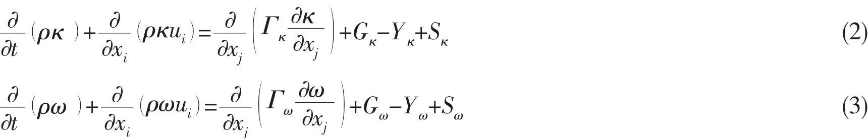
where Γκand Γωrepresent the effective diffusion coefficients of κ and ω,Gκis the turbulence kinetic energy caused by the average flow velocity gradient,Gωindicates the generation of dissipation ω of special turbulence kinetic energy,Yκand Yωare the dissipative coefficients of κ and ω,Sκand Sωare the user-defined source terms.
The pressure equation is numerically discretized by the standard discrete format.And the second upwind scheme is applied to the discretization for the momentum equation,turbulent flow equation and transport equations of Reynolds stressed.For the pressure-velocity coupling problem,SIMPLEC algorithm is adopted numerically.
1.3 Mesh approach
Star-CCM+,which is a commercial URANS code,has provided many mesh discretization methods and dynamic mesh approaches.The selfadapting trim mesh discretization method and overset grids were chosen to carry out calculations in present paper.The principle and concrete steps for the self-adapting trim mesh discretization are given in Ref.[12].The overset grids methodology is a mature and practical technology for the simulation of bodies in relative motion.During the mesh discretization,the domain is split into background region and motion region as shown in Fig.1.The background region is stationary respect to the earth coordinate and the motion region,which is build up around the calculation body,moves with the submarine.These two regions use interpolation at appropriate points to couple the solution on different grids.Any points that lies outside the domain of interest are marked for exclusion from the computations and are termed ‘hole points’.Detailed descriptions of the overset grids strategy can be found in Ref.[13].
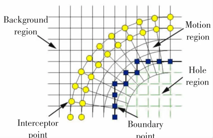
Fig.1 Overset grids strategy
1.4 Kinematics of motions and solution strategy
Two coordinate system types,namely absolute inertial earth-fixed coordinate E-ξηζ and non-inertial body-fixed coordinate O-xyz,are defined to solve a submarine’s motions,see Fig.2.The origin of body-fixed coordinate is located at the centroid of the submarine,which is about 2.01 m and 0.24 m away from model’s bow and baseline respectively.These two coordinate systems overlap completely before the submarine rising.
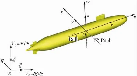
Fig.2 Definitions of the coordinate systems
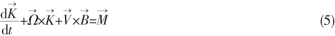
The 4DOF motion is described by the roll and pitch with respect to the O-xyz frame and by the translation in ξ and ζ directions respect to the E-ξηζ frame.Definitions of the motion parameters are shown in Fig.2.The rigid model obeys Newton’s second law for translational motion and the Euler equations for rotation.The concrete equations of motion are shown in formula(4)and(5).

During these simulations,the hydrodynamic force and moment acting on the submarine are evaluated by integrating pressure and shear data along the surface of the submarine and the motion strategy can be obtained based on the equations mentioned above.The overall solution strategy is presented in reference to Fig.3.
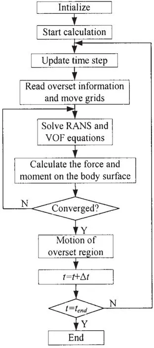
Fig.3 Solution strategy
2 Geometry and conditions
Suboff is a notional submarine model designed by DARPA(Defence Advanced Research Projects Agency)to help building a validation database for a submarine CFD analysis software.A series of captive-model experiments have been performed by many international and domestic organizations to measure the hydrodynamic force and moment acting on the model and it is also chosen for present research.Main particulars of the calculation model are listed in Tab.1.The computations were started with the center of gravity submerged 6 m below the free surface and as the wave pattern fully developed at t=10 s,4DOF motion of the model was released with the buoyancy 3.5%higher than the weight.
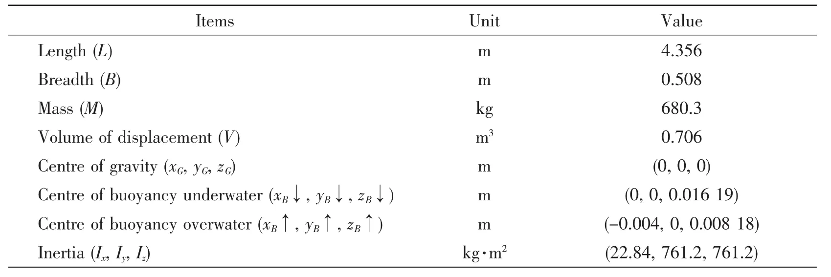
Tab.1 Main particulars of the calculation model
3 Computational domain and mesh discretization
The initial computational domain,including background and overset region,is presented in Fig.4.The background region is cuboid-shaped with the size of 6.4L×3.4L×3.8L and the overset region is established with 1.4L×3.0B×3.0B around the submarine,where L is the length of the submarine.The boundary conditions set for the hull and appendages are no-slip wall and the conditions of far field boundaries can be different for simulations in calm water and waves,as shown in Tab.2.
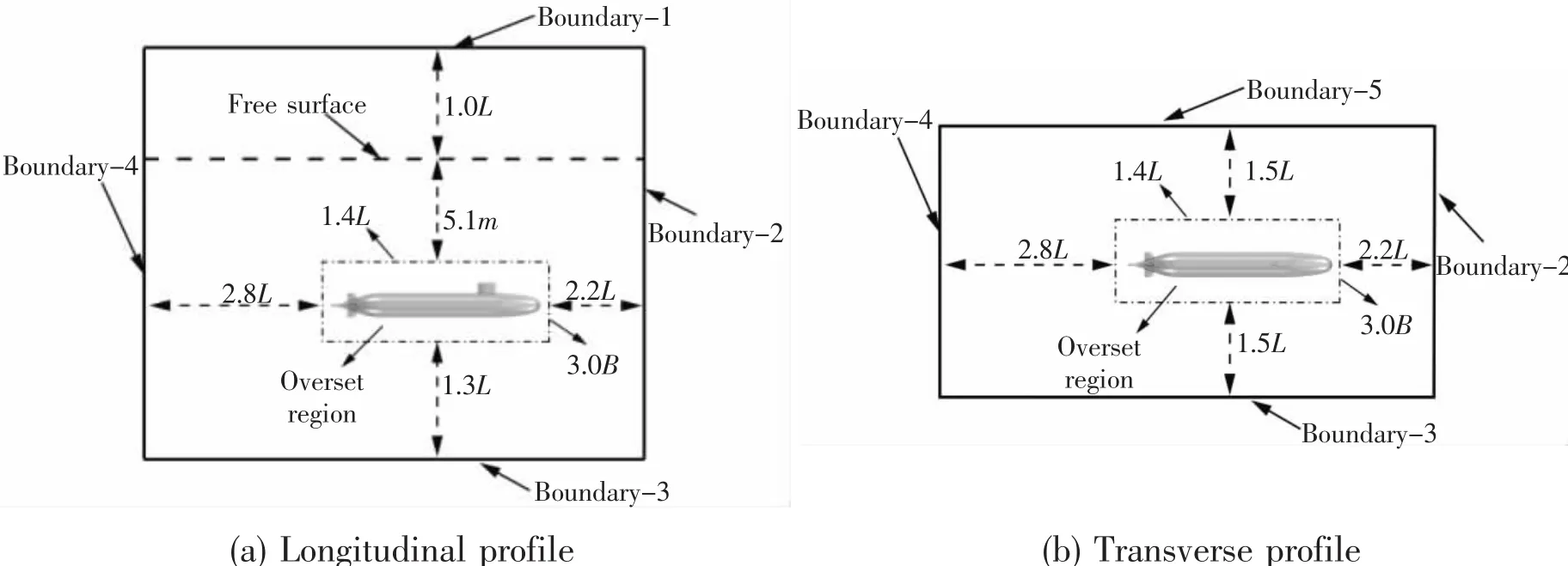
Fig.4 Computational domain for numerical simulation
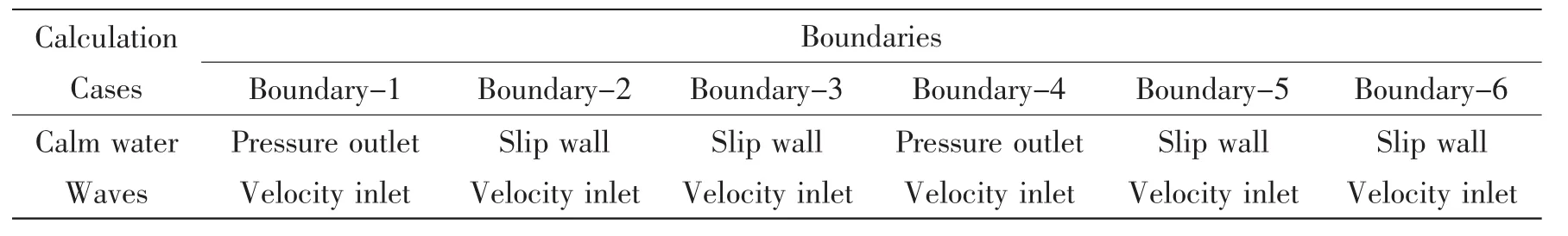
Tab.2 Boundary conditions for different calculation cases
To capture the VOF free surface,refinement grids were set up in both background and overset region,as shown in Fig.5.Meanwhile,to resolve near field viscous flow features around the submarine accurately,systematic grid refinement was constructed to satisfy the y+~1 requirement of the SST k-ω model with near-wall integration,see Fig.6.The number of computed cells is about 165 million for overset region and 352 million for background region.
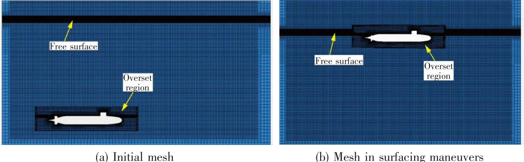
Fig.5 Profile meshes of computational domain
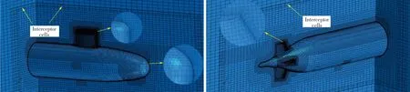
Fig.6 Surface grid discretization
4 Validation for numerical wave-making
The numerical wave tank was established to simulate a submarine’s surfacing maneuvering in calm water and waves.According to the linear wave theory in infinite deep water,the wave generation model was implemented based on the RANS code Star CCM+,whose regular waves were defined as follows:

where ω is the heave natural frequency,g is the gravity constant,k is the wave number,a is the wave amplitude,U is the velocity set for inlet boundary,x and z are the longitudinal and vertical coordinate of fluid particles respectively.
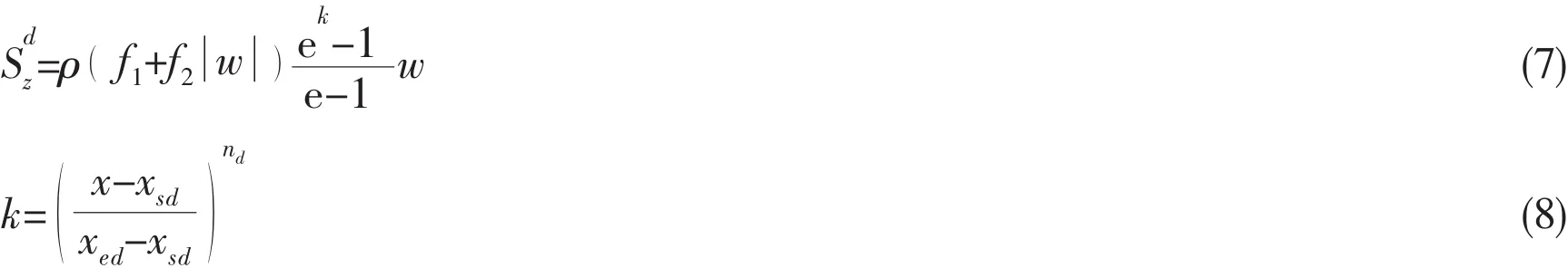
To keep stabilization of the outlet,a sponge layer was set at rear of the tank,about one ship length region away from the outlet,to absorb the wave reflection,which was achieved by the resistance-term addition into the momentum source function,shown as formula(7)and(8).
The 5th-order Stokes waves were simulated based on the method described above and for all the waves,the amplitude Hwand wavelength λ maintained as constant value of 0.127 m and 7.84 m respectively.The initial and fully developed head wave patterns colored elevation are shown in Fig.7.The clear wave patterns indicate that the current method is suitable for wave-making.
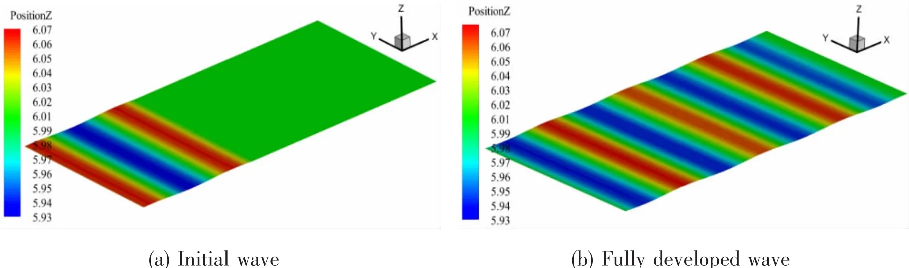
Fig.7 Wave patterns of free surface
Fig.8 shows the calculation result of the regular wave compared with theoretical value.Overall,the calculation results agree well for the longitudinal range-2.5L<X<3.0L with the damping zone set for X≥3.0L region as mentioned above.
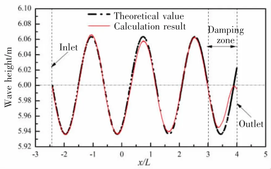
Fig.8 Comparison of the calculation result and theoretical value for VOF wave
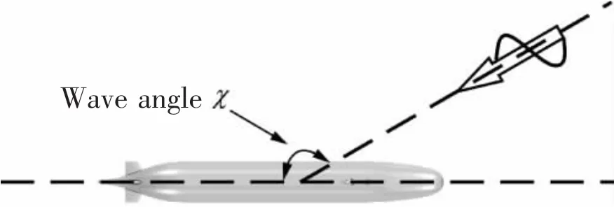
Fig.9 Definition of the wave angle χ
5 Results and discussion
5.1 Motion characteristics for surfacing maneuvers
In this paper,surfacing maneuvers were simulated under calm water,head wave and oblique wave conditions.The wave angle χ,which is defined in Fig.9,set for head wave and oblique wave conditions is 180°and 150°,respectively.Parameters for the computational model and wave conditions have been presented in the above sections.Figs.10-12 show time histories of depth,pitch,roll in Fig-(a)and rising velocity Vζ=∂ζ/∂t,roll rate,pitch rate in Fig-(b),respectively.The positive directions of these parameters are shown in Fig.2.
Inspection of the figures shows that:
(1)The pitch motion represents similar laws versus time under different free surface conditions before the model reaches the free surface.The trim by stern and bow down pitch occur during this stage successively.For example in calm water,with the submarine released at t=10 s,the bow goes up to 7.0°at t=16.3 s and then decreased to 0°at t=16.2 s just as shown in Fig.10(a).With the submarine reaching free surface,the pitch reduces to the minimum value,which is about-3.2°at t=19.8 s.However,comparied with the pitch motion,the roll angle varies slowly with a small range from-0.54°to 0.52°.
(2)The free surface conditions have little effect on the submarine’s vertical motion with the model rising underwater,including surfacing trajectory and velocity.The time consuming for the submarine rising from ζ=0 m to 5 m was all about 20.6 s in calm water,head wave and oblique wave conditions.The rising velocity increases first and then decreases with the maximum 0.6 m/s at t=17.5 s.
(3)With the submarine reaches out of the free surface at t=21.86 s in calm water,the bow down posture changed to stern trim with a pitch rate of approximately 13.0°/s and the roll amplitude increases to about 0.8°.Under the influence of inertia,the submarine surfaces out the free surface with the vertical velocity Vζ=0.48 m/s and after continuous heaving,the amplitude of the vertical motion decreased by the fluid’s damping effects.
(4)After t=35 s,the sailing state can be remarkably different for the three cases,which is mainly determined by surface conditions.The amplitudes of heaving,roll and pitch tend to be 0 without external disturbances in calm water.But in head waves,the pitch motion varies periodically with the time and the roll amplitude in oblique wave is much larger than the other two conditions.
Fig.10 Surfacing maneuvers in calm water
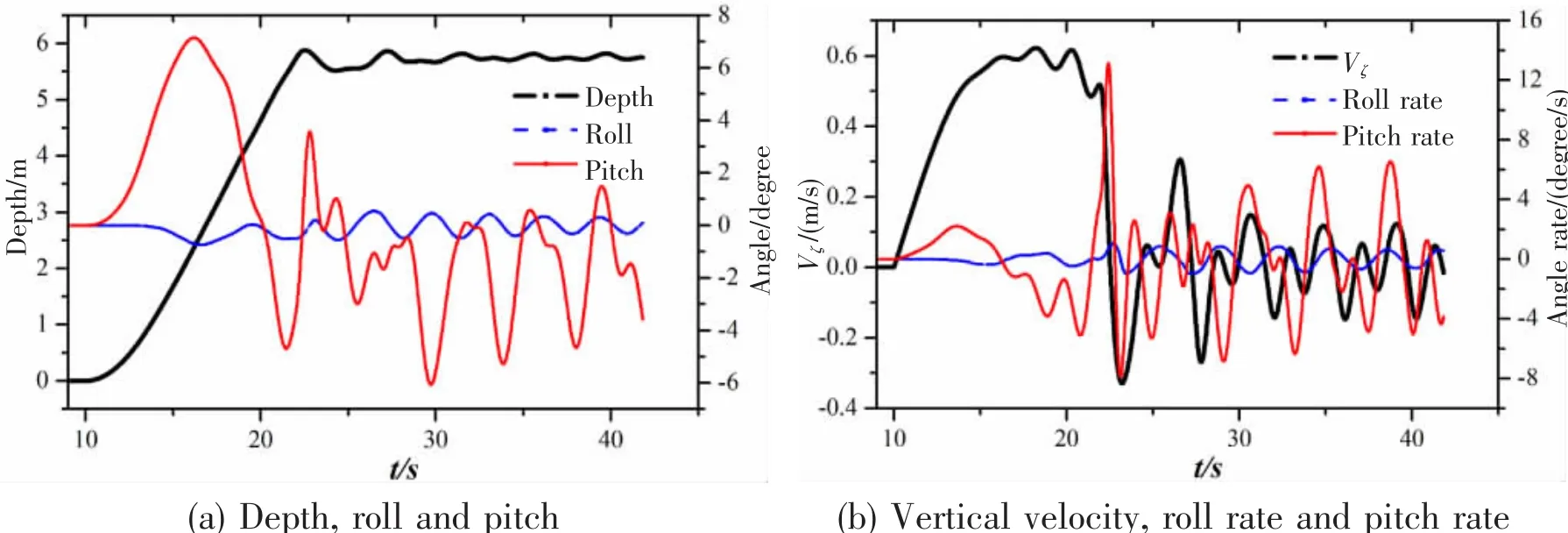
Fig.11 Surfacing maneuvers in head wave(χ=180°)
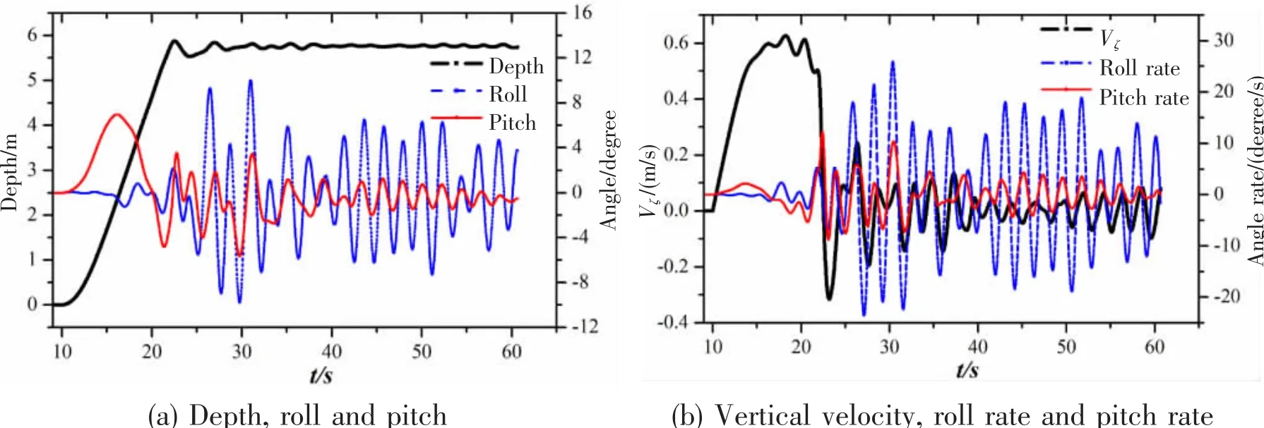
Fig.12 Surfacing maneuvers in oblique wave( χ=150°)
5.2 Flow field and visualization
Based on RANS maneuvering approach,analysis and visualization of the viscous flow field around the submarine can be provided directly.Fig.13 shows the longitudinal profile of the computational domain colored with vertical velocity for calm water condition.The progress of upright floating,stern trim and bow down pitch is shown clearly with the submarine surfacing underwater,just as described in the above section.A close inspection to Fig.13(a)reveals that the velocity distribution is rather uniform for the initial surfacing stage.But with the submarine rising in ζ direction,the vertical velocity for the flow around the stern can reach to 0.99 m/s at t=16.5 s,accompanying with a stern trim position,see Fig.13(b).Notice that as the submarine surfacing near the free surface at t=20.8 s,the vertical velocity for the wake flow shown in Fig.13(d)has a little decrease comparied with the situation at t=19.5 s,as shown in Fig.13(c),but the vertical velocity of the flow near the bow increases to peak value 1.14 m/s.In addition,inspecting Fig.13(b),(c)and(d),there is a certain translation in ξ direction with the dynamic lift caused by asymmetric pressure distribution on the model’s surface and the fluid around the submarine tends to flow from bow to stern during underwater surfacing progress.
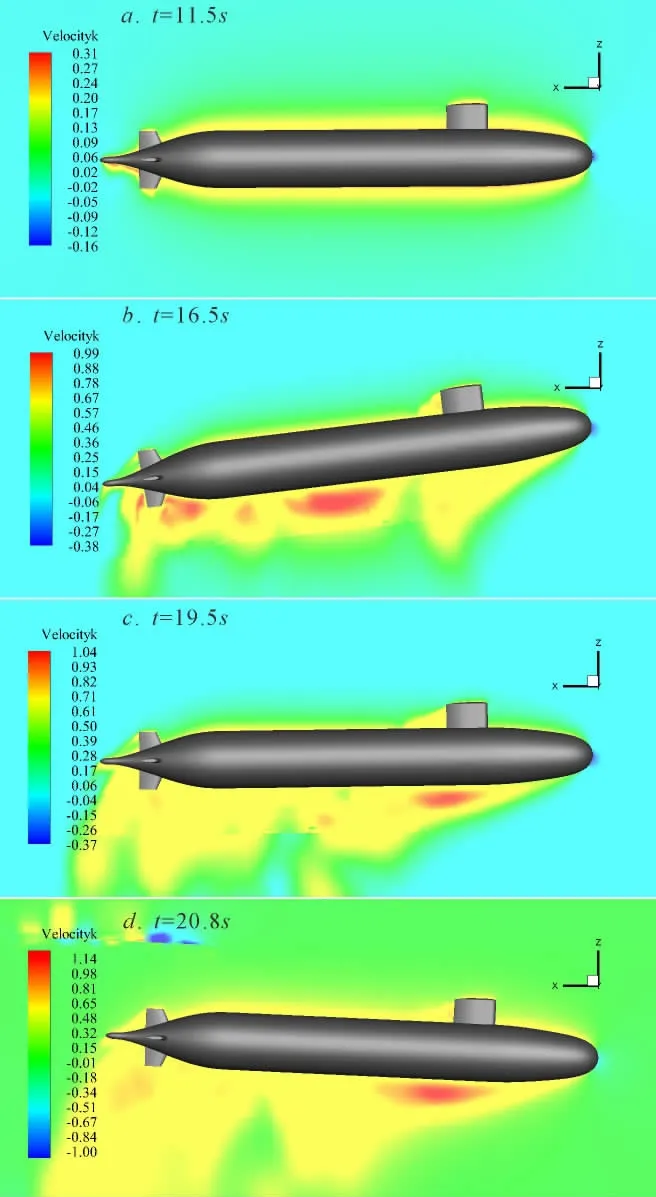
Fig.13 Vertical velocity distribution around a rising submarine in calm water
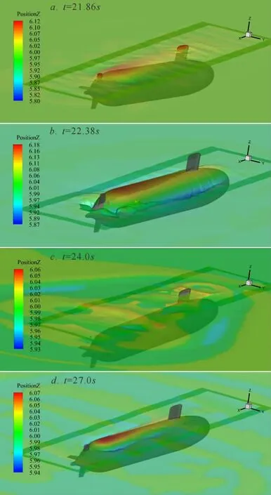
Fig.14 Instantaneous free surfaces colored by elevation for surfacing condition in calm water
The wave patterns colored with elevation for the surfacing conditions are shown in Figs.14-16.It can be seen that based on present method,the instantaneous view with the submarine surfacing out the free surface can be captured vividly.In calm water,the submarine surfaces out the free surface without external interference at t=21.86 s and with the effect of inertial,the model reaches to the highest position at t=22.28 s and then falls back into water at t=24.0 s again.This progress for wave conditions is much more complex accompanied with roll and pitch aroused by wave fluctuation and incidence angle,as shown in Figs.15 and 16.Similarly,for all the other two cases,the submarine represents large-amplitude motions during the initial 3 s after submarine surfacing out the free surface but somewhat decreases due to fluid damping effects along with the time.
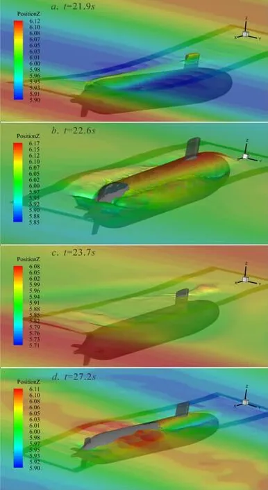
Fig.15 Instantaneous free surfaces colored by elevation for surfacing condition in head wave(χ=180°)
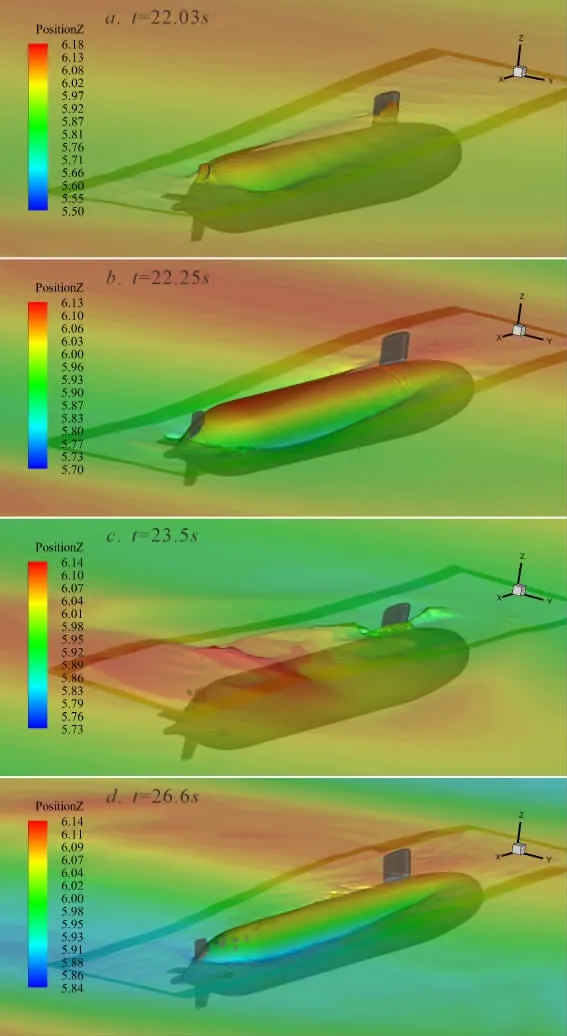
Fig.16 Instantaneous free surfaces colored by elevation for surfacing condition in oblique wave(χ=150°)
6 Conclusions
A method for RANS simulation of a submarine’s surfacing maneuvering is presented.Simulations of buoyantly rising maneuvers for Suboff model were carried out in calm water and regular waves.From this numerical study,the following conclusions can be drawn:
(1)The instantaneous view with submarine surfacing out the free surface can be captured based on current method and reasonable characteristics of motion demonstrate that the current method is feasible and potential for direct computation of submarine’s emergency surfacing in severe environments.
(2)While the submarine rising underwater in different surface conditions,the trim by stern and bow down pitch occur during this stage successively with similar variation law.Before the submarine reaches the free surface,a notable bow-down attitude should attract more attention in future study.
(3)Comparied with clam water condition,surfacing maneuvering in waves is much more complex accompanied with roll and pitch aroused by wave fluctuation and incidence angle.For all the simulation cases,the submarine represents large-amplitude motions after submarine surfacing out the free surface but somewhat decreases due to fluid damping effects along with the time.
杂志排行

船舶力学的其它文章
- Dynamic Stability of Liquefied Cargo Ship in Waves
- Investigation on Time Domain Motions for Ship and Floating Structure and Coupled with Nonlinear Sloshing
- A Revised Method for Predicting Added Waves Resistance Based on Comparison of Theoretical and Empirical Results for VLCC Hull Forms
- 3D Nonlinear Hydroelastic Response and Load Prediction of A Large Bulk Carrier in Time Domain
- Strength Characteristics of Maraging Steel Spherical Pressure Hulls for Deep Manned Submersibles
- Research on Stress Intensity Factors for the Deflected Crack of CTS Specimen