Buck开关变换器的基本参数设计及仿真分析
2016-11-09钟明航
钟明航

摘要:本文主要用电力电子仿真软件Saber,对电力变换器中的降压Buck变换器进行仿真分析,给出Buck变换器系统工作频率的计算方法、过流保护方式和元件器参数选型原则。变换器开关管一般依据电路参数选取可以通过相应电流并承受相应电压的MOS器件,MOS管为电压控制型器件,电路要求MOS管有一定的开通和关断速度,驱动电路的设计就尤为关键,文中给出了一种三极管结构的驱动电路以及驱动电路各元器件参数计算方法。用Saber绘制Buck电路并仿真,结果表明参数设计合理。
关键词:Saber Buck 仿真 三极管驱动
中图分类号:TM461.5 文献标识码:A 文章编号:1007-9416(2016)09-0131-02
Abstract:In this paper, power electronic simulation software Saber, on the power Buck converter simulation and analysis, calculation method gives Buck converter system operating frequency, mode and overcurrent protection component parameter selection principle. Converter switch circuit based on general parameters selected by the respective current and withstand voltage corresponding MOS device, MOS tube is a voltage-controlled device, MOS transistor circuit requires a certain degree of turn-on and turn-off speed, the drive circuit design is particularly critical, the paper gives a drive circuit transistor structure and the parameters of the various components driving circuit calculation. Draw with Saber Buck circuit and simulation results show that reasonable design parameters.
Key Words:Saber;Buck;Simulation;Transistor Drive
1 引言
煤矿井下存在多种电器设备,设备至关重要一部分是电源,电源为各核心模块提供动力,而复杂系统中各模块工作于不同的电压,需要不同的电压变换电路,Buck电路作为一种直流-直流降压变换电路,在手持探地雷达、井下通讯设备、井下显示器、低压传感器等低电压用电设备电路的场合均有应用。Saber软件是一款专业的电力系统仿真软件,对于给定的电路原理图,方便快捷的实现多种参数仿真分析。利用辅助设计软件仿真分析,能在实际电路搭建之初验证电路的可行性,并指导变换器设计。
2 Buck变化器电路原理分析
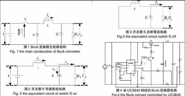
Buck变换器主电路结构如图1所示。Buck变化器由开关管S、电感L、续流二极管D、储能滤波1电容C、负载电阻五部分组成[1]。在主电路结构中,为变换器输入电压,为变换器输出电压。
分析Buck变换器在一个周期内各元器件工作状态:
