Large Thrust Trans-scale Precision Positioning Stage Based on Inertial Stick-SliP Driving
2015-11-24LiZongwei李宗伟ZhongEowen钟博文WangZhenhua王振华JinZiqi金子祺SunLining孙立宁ChenLinsen陈林森
Li Zongwei(李宗伟)'Zhong Eowen(钟博文)*'Wang Zhenhua(王振华)' Jin Ziqi(金子祺)'Sun Lining(孙立宁)'Chen Linsen(陈林森)2
1.College of Mechanical and Electrical Engineering&Collaborative Innovation Center of Suzhou Nano Science and Technology'Soochow University'Suzhou 215021'P.R.China;
2.Suzhou Industry Park Postdoctor Station'SVG Digitoptics Co.'Ltd'Suzhou 215026'P.R.China
Large Thrust Trans-scale Precision Positioning Stage Based on Inertial Stick-SliP Driving
Li Zongwei(李宗伟)1'Zhong Eowen(钟博文)1*'Wang Zhenhua(王振华)1' Jin Ziqi(金子祺)1'Sun Lining(孙立宁)1'Chen Linsen(陈林森)2
1.College of Mechanical and Electrical Engineering&Collaborative Innovation Center of Suzhou Nano Science and Technology'Soochow University'Suzhou 215021'P.R.China;
2.Suzhou Industry Park Postdoctor Station'SVG Digitoptics Co.'Ltd'Suzhou 215026'P.R.China
Eor the smaller thrust'it is difficult to achieve 3D trans-scale precision positioning based on previous stick-slip driving.A large thrust trans-scale precision positioning stage is studied based on the inertial stick-slip driving.The process of the movement is divided into two steps'i.e.'the″sliding″phase and the″stickness″phase. In the whole process'the kinematics model of the inertial stick-slip driving is established'and it reveals some factors affecting the velocity of inertial stick-slip driving.Eurthermore'a simulation of movement is preformed by Matlab-Simulink software'and the whole process of the inertial stick-slip driving is displayed.After one experimental prototype is designed'the back and forth velocity is tested.Einally'the simulation verifies the accuracy of the kinematics model.
PZT actuator;inertial stick-slip driving;trans-scale;precision positioning
0 Introduction
Micro-driving system'which is widely approved in technology and industry'is a very important part of micro electro mechanical system(MEMS).Eecause of the advantages of the high displacement positioning accuracy'fast response' large driving force'low driving power and the wide working frequency'etc'the piezoelectric ceramic actuators have been comprehensively utilized in precision machinery.Usually'majority of positioning and operation are driven directly by PZT in precision positioning technology.However'the devices of PZT actuator work in lower micron range'or even in sub-micron range.At present'the large trans-scale precision positioning technology'with not only nanometer positioning accuracy'but also millimeter moving range even greater movement scale'has become crucial technical issues in the field of nanotechnology.Eor the sake of micro-operation and observation in the limited space'some scholars extend the moving range to tens of millimeter by means of accumulating deformation of piezoelectric ceramics.Some typical trans-scale precision positioning technologies have been further studied for now'such as macro-micro hybrid driving'piezoelectric ultrasonic motor driving'piezoelectric inchworm driving'stick-slip driving'and so on. Inertial stick-slip driving technology'which has better flexibility and higher integration'also satisfies the above requirement.It has an extensive application prospect in the field of nanotechnology'such as cell operation'burning disks'assembly and packaging of MEMS device'etc[1-2].
1 PrinciPle of Inertial Stick-SliP Driving
Specifically'the driving is divided into stepping-mode and scanning-mode[3-5].In the stepping-mode'the sawtooth wave and the principle of an inertial stick-slip driving are shown in Eig.1(a).Driving the step signal from①to②' the power drives the piezoelectric ceramic in great acceleration motion.Meanwhile'slider and inertial mass generate different micro displacement in two opposite directions.The sum of the displacement of slider and inertial mass is equal to the deformation of piezoelectric ceramic.When the driving signal applied on the piezoelectric ceramic is from②to③'the slider holds its position under the effect of friction force'but the inertial mass walks toward the slider.As a result'the model of inertial stick-slip driving fulfills a cycle of displacementΔXi.Repeating the process of movement'the model will achieve the accumulation of displacement step by step.The aim of large trans-scale movement accomplishes.
The total displacement of such a macro/micro arrangement is written as

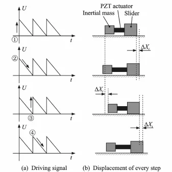
Eig.1 Principle of inertial motion
where the displacement of the stepping-mode Xstepis replaced by a sum of stepsΔXi'which have previously been performed'and Xscanthe displacement of the scanning-mode.There is function relationship between voltage values V(t)and Xscan. Approximately'the displacement of the seanningmode Xscanis linear with input voltage V(t).
2 Model of Inertial Stick-SliP Driving
Actually'the model of inertial stick-slip driving can be described as two degrees of freedom system.As shown in Eig.2.
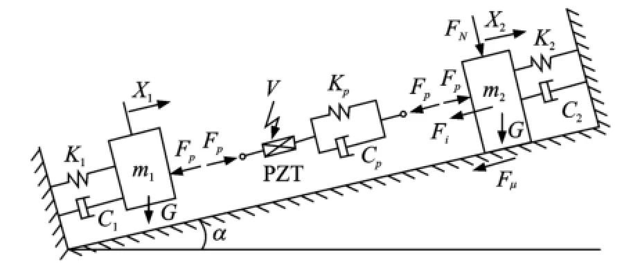
Eig.2 Kinematics model of inertial stick-slip driving
Under the action of external electric field' PZT actuator will produce the accumulation of charges which is called polarization.PZT produces strain under the both action of outer and inner electric field[6].PZT can be considered as a big capacitance in electric field.According to the capacitance charge-discharge formula'the voltage on both ends of PZT actuator V(t)can be expressed as

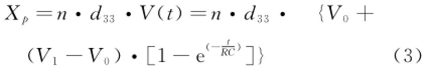
where V0=0'V1is the output value of the driving power'and V1=V.Therefore'the Eq.(3)can be simplified as

where V0is initial voltage'V1the voltage of external electric field'R the resistance of Chargedischarge circuits'and C the equivalent capacitance of PZT.
Apparently'the deformation of PZT can be described as
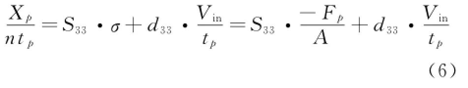
Otherwise'according to the piezoelectric equation
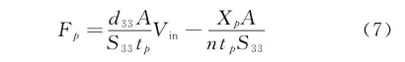
whereεis the strain of piezoelectric in the direction of axis d l/l=Xp/(ntp)'S33the modulus of elasticity of piezoelectric'σthe stress of piezoelectric in the direction of axis'd33the piezoelectric constant'Vinthe voltage of driving'and tpthe thickness of piezoelectric.
where Fpis generated by PZT and imposed on slider and inertial mass.Fpcan be observed as
Like the two degrees of freedom system'the motion of the inertial stick-slip driving can be described by differential equation.The equation of motion can be written as
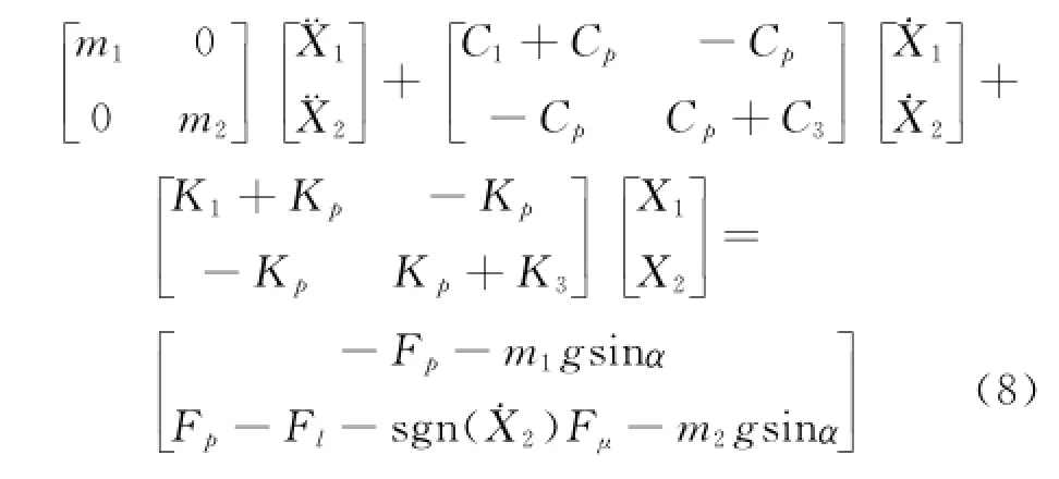
When the inertial stick-slip driving system is in horizontal plane'i.e.α=0'stiffness damping coefficients C1=0'K1=0'C3=0'K3=0'and the external load Fl=0'FN=0'Eq.(8)can be simplified as
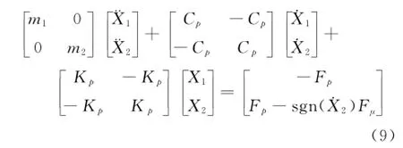

Specifically'Fμis the friction between the substrate and slider.Coulomb friction model is used to calculate the friction force[7].
Eq.(9)is the form of second-order matrix.More simplified form is shown as

We can approximate displacement X2with Xp+ X1of m2in Eq.(10)to obtain the equation of motion in its simplified form as

where Ff=(m1+m2)gμ'μis the friction coefficient between the slider and the environment ground.
Eased on the driving principle and the kinematics model of the inertial stick-slip driving system'the process of the movement will be executed by Matlab-Simulink software.The aim is to understand the principle of inertial stick-slip driving'and obtain displacement and velocity curves. Intuitively'the effect of the friction force and the mass of slider and inertial part on the movement have been discovered in theory.
Eig.3 is the simulation process diagram of inertial stick-slip driving system.The parameters used in simulation are shown in Table 1.
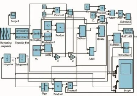
Eig.3 Simulation diagram in Matlab-Simulink
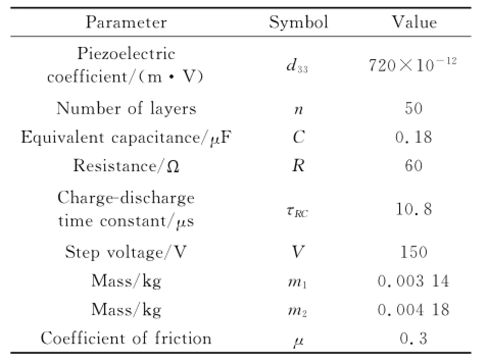
Table 1 Parameters in dynamic model simulation
According to the parameters given in Table 1 and the simulation model shown in Eig.3'the displacement curves of PZT'inertial mass'sliderand the instantaneous velocity curves of inertial mass'slider can be obtained'as shown in Eig.4.

Eig.4 Displacement and instantaneous velocity
In Eig.4'the PZT actuator is driven by the sharply rising signal from①to②.The slider walks toward the positive direction'while the inertial mass goes toward the negative direction. The sum of the displacement of slider and inertial mass is equal to the deformation of piezoelectric ceramic'i.e.|X2-X1|=|Xp|.
When PZT shortens slowly'i.e.″stick″phase'corresponding to②and③in Eig.1(a)' the state of motion of slider can be described as ˙X2=0'¨X2=0.In the sticking phase'Fμis static friction'which is be concerned with Fp'as shown in Eq.(13).

Repeating the process of the movement'the inertial stick-slip driving model achieves accumulating the displacement of every single step. Commonly'we call it the stepping-mode movement.
3 Design and ExPeriment
3.1 Structure design
According to the inertial stick-slip driving principle'a large thrust trans-scale precision positioning platform has been designed'which is driven by PZT stack actuator(5 mm×5 mm× 6 mm).The maximum deformation of PZT is 5.34μm under 150 V.The friction between the axle and the V-groove can be adjusted by the spring.The length of the spring is 30 mm and the stiffness of the spring is 0.38 N/mm.The mass of slider and inertial part will be transformed by means of increasing or reducing the number of copper billet on each side.The movement range of the prototype is 20 mm along the direction of the PZT deformation.The thrust of the prototype will reach 8 N.Each part of the thrust transscale inertial stick-slip driving platform is shown in Eig.5.

Eig.5 3D model of inertial stick-slip driving
3.2 PrototyPe exPeriment
A prototype of novel trans-scale precision positioning stage based on the inertial stick-slip effect is processed and the prototype will be tested by the equipments shown in Eig.6.
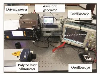
Eig.6 Experimental equipments in prototype testing
Referring to the Eq.(11)and the result of simulation of inertial stick-slip movement'the characteristics of kinematics of inertial stick-slip driving system relates to the mass of slider and inertial part'friction'the frequency of the input voltage'etc.
In the experiment'the form of wave is generated by waveform generator.To test the forward and the backward velocity'two types ofsawtooth wave are inputted'respectively.Moreover'the external step voltage is applied to inertial stick-slip stage by the PZT driving power.Polytec laser vibrometer records the displacement of the prototype'and the actual forward displacement curve in Eig.7 is similar to the simulation result in Eig.4(a).The forward and the backward velocities are as follows
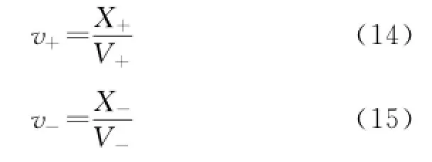
where v+is the forward velocity'v-the backward velocity'X+the forward displacement'X-the backward displacement'T+the time taken by the forward walking'and T-the time taken by the backward walking.

Eig.7 Eorward displacement curve of prototype
As discussing the mass of inertial part effect on the velocity of the inertial stick-slip driving stage'the friction Fμ'the frequency of the input voltage f and the amplitude the input voltage U are considered as constant.The mass of slider m2is 3.12 g.The mass of inertial part m1is independent variable'and the velocity of the stage V is induced variable.Increasing or decreasing the mass of inertial part is available by adding or taking down the copper billet from the stage.The result is shown as Eig.8.
In Eig.8'the bigger the mass of inertial part is'the faster the stage work.In other word'the stage walks more quickly along with the mass of inertial part increasing.Eesides'the forward velocity comes closer to the reverse one when the mass of inertial part increases.The rule shown in Eig.8 matches the Eq.(11)in the kinetics model.

Eig.8 Mass of inertial part m1affecting velocity
Moreover'in Eq.(11)'the characteristics of kinematics of inertial stick-slip driving system is related to Fμ.To study the friction impact on the process of the movement'the adjusting nut is screwed to compress or loosen the spring.Different length of spring supply different pressure on the axle'and that means different friction on the contact interface.Obviously'the larger the deformation of the spring is'the larger the friction is.Some data have been sorted as shown in Eig.9.
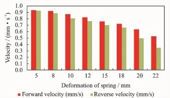
Eig.9 Deformation of spring affecting velocity
In the experiment'the mass of the slider m2=3.12 g'the mass of inertial part m1=4.18 g'the frequency of the input voltage f=1 k Hz' the amplitude of the input voltage U=90 V.All in all'it is concluded that the stage walks more slowly along with the friction on the contact interface increasing.In addition'there is more difference between the forward and the reverse velocities.The experimental result is corresponding to the above kinetics model.
4 Conclusions
The background and the principle of inertial stick-slip driving are introduced.An initial ap-proach in movement modeling of inertial stick-slip driving stage is put forward.The process of the movement is divided into two steps'the″sliding″phase and the″stickness″phase.The movement of the inertial stick-slip driving is simulated by Matlab-Simulink software.Eurthermore'a large thrust trans-scale precision positioning platform is designed.Some experiments are conducted on the platform to verify the accuracy of the kinetics model.Obviously'there is a close relationship between the velocity and some system parameters'the mass of slider and the friction on the surface.Roughly'the larger the mass of inertial part is'the faster does the prototype work.Eut the prototype walks more slowly along with the friction increasing.It is different between the forward velocity and the reverse velocity.Two reasons are taken into account:(1)PZT responses differently in two types of input signal'which are sharp rising and sharp dropping.(2)The friction between the slider and the substrate is different in the forward direction and the reverse direction.
Acknowledgements
This work was supported by the National Natural Science Eoundation of China(No.51175358)'the Natural Science Eoundation of Jiangsu Province(No.EK20140345)' Colleges and Universities Natural Science Eoundation of Jiangsu Province(No.14 KJE460025)'and the National Science Eoundation for Post-Doctoral Scientists of China(No.2014 M551651)'the Natural Science Eoundation of Jiangsu Province for Post-Doctoral Scientists(No. 1401073C).
[1] Hunstig M'Hemsel T'Sextro W.Stick-slip and slip-slip operation of piezoelectric inertia drives[J]. Sensors and Actuators A:Physical'2013'200:79-89.
[2] Shimizu Y'Peng Yuxin'Kaneko Junji'et al.Design and construction of the motion mechanism of an XY micro-stage for precision positioning[J].Sensors and Actuators A:Physical J'2013'201:395-406.
[3] Edeler C'Meyer I'Eatikow S.Modeling of stick-slip micro-drives[J].Journal of Micro-Nano Mechatronics'2011'6(3/4):65-87.
[4] Chung G J'Choi K E'Kyung J H.Development of precision robot manipulator using flexure hinge mechanism[C]∥2006 IEEE Conference on Robotics' Automation and Mechatronics.Eangkok'Thailand: IEEE'2006:1-6.
[5] Meyer Christine'Sqalli Omar'Lorenz Heribert'et al.Slip-stick step-scanner for scanning probe microscopy[J].Review of Scientific Instruments'2005'76(6):1-6.
[6] Zhong Eowen'Sun Lining'Chen Liguo'et al.The dynamics study of the stick-slip driving system based on LuGre dynamic friction model[C]∥The 2011 IEEE International Conference on Mechatronics and Automation(ICMA 2011).Eeijing:IEEE'2011:7-10.
[7] Chris Wensrich.Slip-stick motion in harmonic oscillator chains subject to coulomb friction[J].Tribology International'2006'39(6):490-495.
(Executive editor:Xu Chengting)
TH703 Document code:A Article ID:1005-1120(2015)02-0204-06
*CorresPonding author:Zhong Eowen'Lecturer'E-mail:zhbw@suda.edu.cn.
How to cite this article:Li Zongwei'Zhong Eowen'Wang Zhenhua'et al.Large thrust trans-scale precision positioning stage based on inertial stick-slip driving[J].Trans.Nanjing U.Aero.Astro.'2015'32(2):204-209.
http://dx.doi.org/10.16356/j.1005-1120.2015.02.204
(Received 5 January 2015;revised 23 January 2015;accepted 30 January 2015)
猜你喜欢
杂志排行

Transactions of Nanjing University of Aeronautics and Astronautics的其它文章
- StePPing Control Method of Linear DisPlacement Mechanism Driven by TRUM Based on PSoC
- Design and ExPeriment of Vertical Motion Dual-stage with Piezo-actuated NanoPositioning Stage
- Intelligent Control Algorithm of PTZ System Driven by Two-DOF Ultrasonic Motor
- Dynamic Model Identification for Ultrasonic Motor Frequency-SPeed Control
- Dynamic Loads and Wake Prediction for Large Wind Turbines Based on Free Wake Method
- Numerical Investigation on Drag Reduction Effect by Mass Injection from Porous Boundary Wall