Intelligent Control Algorithm of PTZ System Driven by Two-DOF Ultrasonic Motor
2015-11-24WuSongsen吴松森LengXuefei冷雪飞JinJiamei金家楣WangEihui王碧辉MaoXingyun毛星云
Wu Songsen(吴松森)'Leng Xuefei(冷雪飞)*'Jin Jiamei(金家楣)' Wang Eihui(王碧辉)'Mao Xingyun(毛星云)
1.College of Astronautics'Nanjing University of Aeronautics and Astronautics'Nanjing 210016'P.R.China;
2.State Key Laboratory of Mechanics and Control of Mechanical Structures'Nanjing University of Aeronautics and Astronautics'Nanjing 210016'P.R.China
Intelligent Control Algorithm of PTZ System Driven by Two-DOF Ultrasonic Motor
Wu Songsen(吴松森)1'Leng Xuefei(冷雪飞)1*'Jin Jiamei(金家楣)2' Wang Eihui(王碧辉)1'Mao Xingyun(毛星云)1
1.College of Astronautics'Nanjing University of Aeronautics and Astronautics'Nanjing 210016'P.R.China;
2.State Key Laboratory of Mechanics and Control of Mechanical Structures'Nanjing University of Aeronautics and Astronautics'Nanjing 210016'P.R.China
It is difficult for the traditional pan-tilt-zoom(PTZ)system driven by electromagnetic motor to meet the growing demand for video surveillance system.The key challenge is high positioning accuracy'high dynamic performance and miniaturization of the PTZ system.Here a PTZ system driven by two degree-of-freedom obeliskshaped ultrasonic motor with single stator is presented'and its intelligent control algorithm is studied.The structure and driving mechanism of the presented PTZ system are analyzed by both simulation and experiment.To solve the complex nonlinear factors'e.g.time-variation'dead zone'the fuzzy PID control algorithm and the variable gain cross-coupled control strategy are combined to improve the control performance.The results show that the proposed algorithm has faster response'higher precision than traditional control algorithm'and it also has a good robustness to prevent the effect of interference.
ultrasonic motor;PTZ system;fuzzy PID;cross-coupled control
0 Introduction
The pan-tilt-zoom(PTZ)system is the key part of video surveillance system.The traditional PTZ system is commonly driven by multiple electromagnetic motors'which have the disadvantages of complex structure'large volume'slow response'low accuracy'and so on.The drawbacks mentioned above make it difficult to track effectively moving target'which restricts its further development.It becomes more and more important to significantly improve its dynamic performance with the help of high and new technology.
Ultrasonic motor(USM)is a type of electric motor powered by the ultrasonic vibration of the stator'placed against another component'the rotor or slider depending on the scheme of operation(rotation or linear movement)[1].The unique driving mechanism and advantages of USM'such as high torque in low speed'simple structure' fast response'self-locking'high accuracy'antielectromagnetic interference'and so on'make it suitable for application in the PTZ system.
Recently'ultrasonic motors(USMs)with multi degree-of-freedom(DOE)are increasingly attracted.There are many progresses in such research towards basic principle'structure'working mechanism and control algorithm etc'especially for ultrasonic motor with multi DOE.Purwanto et al.[2'3]developed a spherical ultrasonic motor with three DOE.The actuator can provide multi-DOE motion using single stator'which has been applied to the joints of robots'artificial limb'and so on.However'as for application in PTZ system'current research focuses on assembling several single-DOE USMs to achieve multidirection rotation.Gu[4]introduced the realizationof target recognition and tracking system.The pan-tilt can rotate in horizontal and vertical direction by using two traveling wave ultrasonic motors(TWUSMs)served as the driving unit.
A PTZ system driven by a two-DOE ultrasonic motor with single stator is presented in the paper.Taking nonlinear factors into consideration'Euzzy PID control and variable gain crosscoupled control strategy are applied to compensate for dynamic error and improve the performance.The PTZ system reduces system complexity to meet demands for miniaturization and intellectualization'providing a broad prospect for the further development and application.
1 Analysis and Modeling of PTZ System
1.1 Two-DOF USM with single stator
USMs take use of electrical energy to drive piezoelectric element.When the frequency of input signals is adjusted to be consistent with the mechanical resonance frequency'the amplitude of the vibration comes to its peak.With the help of pre-pressure'friction force between the stator and rotor drives the rotor to achieve the rotation or linear movement.Thus'USMs accumulate reduplicate small displacement to get a certain movement.
The two-DOE ultrasonic motor with single stator used herein is composed of an obelisk stator and a base with concave spherical surface. The stator has four square cylindrical structures with polarized piezoelectric pieces affixed on the outside of columns'which is working at the local bending mode.A support plate is placed between the four columns to connect each other'thus fixing the stator[5].
The working principle can be described as follows:the stator has both symmetric and antisymmetric bending vibration modes when applied specific voltage signals on the piezoelectric ceramics'as shown in Eigs.1'2.When operating in symmetrical mode'the stator only has reciprocating vibration in direction of z at the top of the stator'illustrated in Eig.1(a).On the other hand'Eig.1(b)shows vibration only along the x direction in antisymmetric mode.If the excitation signals applied to the piezoelectric plate have a phase difference ofπ/2'the stator works in both symmetric and antisymmetric mode at the same time'making elliptic trajectory at the top.Reverse movement can be achieved if the phase difference between signals is adjusted to-π/2. In addition'it works nearly the same in the y-z plane due to the symmetrical structure of the stator.Therefore'the stator with such a specific structure can realize a two-DOE linear movement.
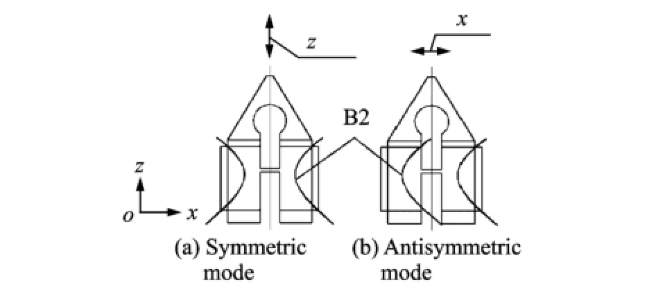
Eig.1 Operating mode of stator
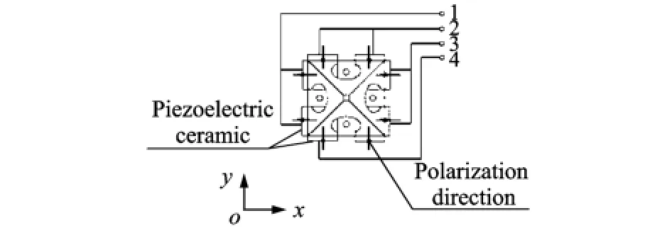
Eig.2 Port number
According to harmonic response analysis of stator conducted by ANSYS'when the amplitude of voltage applied to the piezoelectric is 300 V and damping ratio is 0.3%'the harmonic response frequency ranges from 68.80 k Hz to 69.20 k Hz.
The modal frequency of prototype is measured with the help of PVS-300E-E vibrometers' in order to verify that whether it meets the theory and analysis above or not.Working mode and the modal frequency of the stator can be obtained in the scanning curves shown in Eig.3.
Compared with theoretical calculation'actual working frequency of the prototype is smaller than the value obtained by ANSYS'in which thedifference in modal frequency of anti-symmetric is nearly 0.3 k Hz.
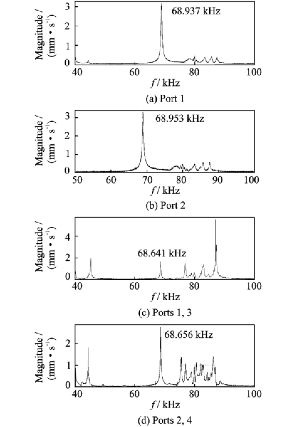
Eig.3 Scanning curves of swept frequency experiment
After scanning the actual modal frequency' accurate amplitude of vibration can be obtained when applied to the voltage with peak-peak value of 300 V at the fixed-frequency above'as shown in Table 1.
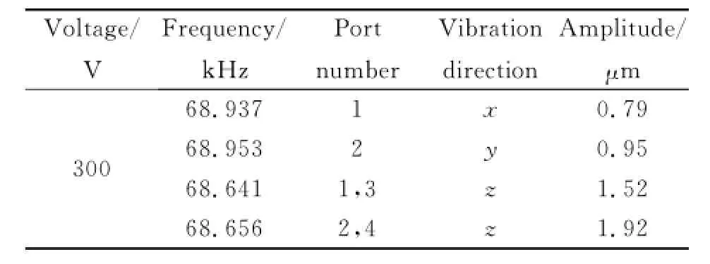
Table 1 ExPerimental results at fixed frequency
The results show that the amplitude along x direction is smaller than y direction and it has difference in the direction of z when applying voltages on different ports.The difference is impacted by structural asymmetry during processing'adhesive technology of piezoelectric and other position error'which will affect the performance of USM.
1.2 Driving mechanism of PTZ system
The stator is pressed to be in contacted with the concave spherical surface by applying the appropriate pre-pressure.Eig.4 shows the machine drawing of PTZ system.
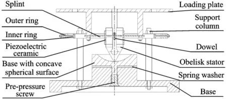
Eig.4 Structure of PTZ system
Analysis for its driving principle is made as follows based on Eigs.2'4.When the signals applied to Ports 1 and 3'are E=-V sinωt and E= -V cosωt'respectively'the top of the obelisk will make a elliptical movement in x-z plane'causing frictional force between the stator and base. If the phase difference is-π/2'opposite direction of rotation appears.The analogous rotation about x-axis can be achieved by adjusting the input terminals as Ports 2 and 4.
Eig.5 illustrates the vertical view of the PTZ system prototype without the camera planted' which shows that the two-DOE rotation is conducted by the two frame gyroscope structure'including inner ring and outer ring.When it rotates about y-axis'stator and splint rotates as a whole part around the axis through inner ring;when it comes to x-axis'stator'splint and inner ring revolves on the axis through outer ring.The camera is planted on the loading plate'driven directly by the single stator.Pre-pressure between the ro-tor and the base can be adjusted by tightening the depth of pre-pressure screw to ensure regular operation.
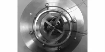
Eig.5 Vertical view of PTZ system driven by two-DOE USM
After a series of tests with measurement equipment and image matching algorithm'the specific performance parameters can be concluded in Table 2.
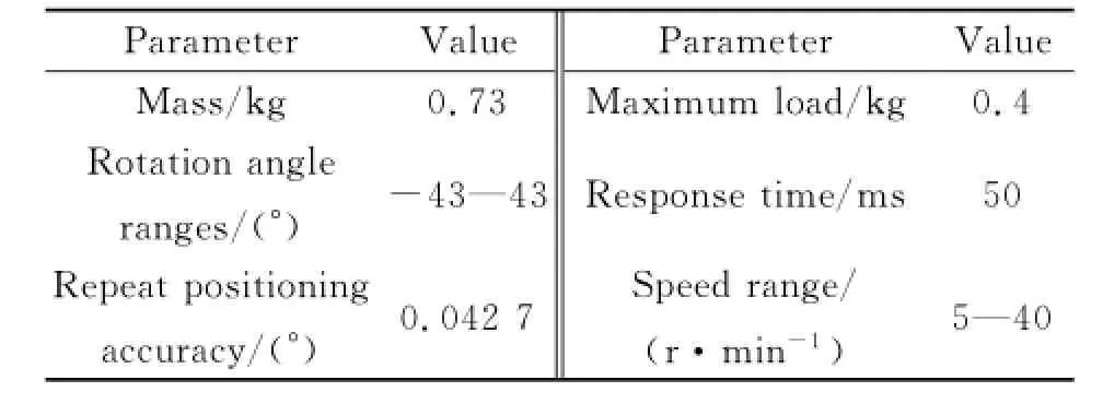
Table 2 Performance Parameters of PTZ system
1.3 Modeling of PTZ system
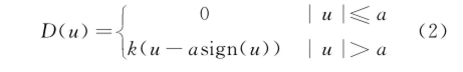
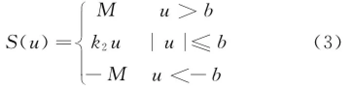
USMs are a complex nonlinear system with mechanical-electric coupling and closed loop controls.Eive types of nonlinearity exist in the system:(1)complex contact friction force;(2)material nonlinearity;(3)slow-changing factors due to temperature;(4)nonlinearity in driving circuit;(5)structural asymmetry caused by machining operation[6].These nonlinear factors are related with various nonlinear phenomena'such as timevariation'drift of resonance frequency'dead zone and saturation.
With regard to such a nonlinear system'it can be illustrated in the describing function method as Eq.(1)
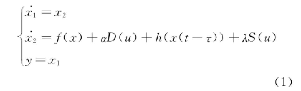
whereχ=(x1'x2)T=(θ'ω)Tis measurable state of the system.θandωstand for angle displacement and angular speed'respectively'u and y the input and output in system.D(u)means the effect of dead-zone'S(u)the saturation'andτthe time-delay constant.Meanwhile'αandλare effect coefficients'respectively.
According to the Wiener-Hammerstein model[7]'Eq.(1)can be decomposed into three parts(Eig.6)'where N(·)combine D(u)and S(u)in paralleling method'and h(t)means time-delay e-τs.f(x)in Eq.(1)and G(s)in Eig.6 both illustrate the linear dynamic system'which is the most concerned part.According to the driving mechanism'the linear part model of PTZ system herein can be simplified as Eq.(4).The obelisk stator and loading plate revolve together on the ring center'driven by the friction torque and load torque in the tangential direction only.Therefore'the equation of motion in tangential direction can be described by

where J is the moment of inertia'dτthe damping coefficient in the tangential direction'ωRthe rotation angular speed of PTZ'and Tloadthe load torque.
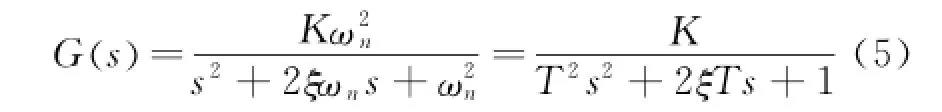
Taking the advantages of USM such as high accuracy'fast response into consideration'we choose to control the position of PTZ system rather than speed control'which means setting a certain angleθas expected position.Then'PTZ system input a value U(U depends on the control method of motor'such as voltage frequency or phase regulation)'which can change the vibration mode and adjust the value of friction to alter rotational angular velocity.According to Eq.(4)'the linear part of the PTZ system can be regarded as a second-order dynamic system'with inputting U and rotation angle'and the transfer function is
Parameters can be chosen from the response result of the PTZ system.A camera with 30 f/s is used as positioning device to take pictures and imagine matching algorithm worked as positionfeedback.
As shown in Eig.7'pictures are taken every 33 ms and each pixel offset stands for the current angular displacement.Einally'after data fitting' the transfer function can be expressed as
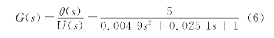
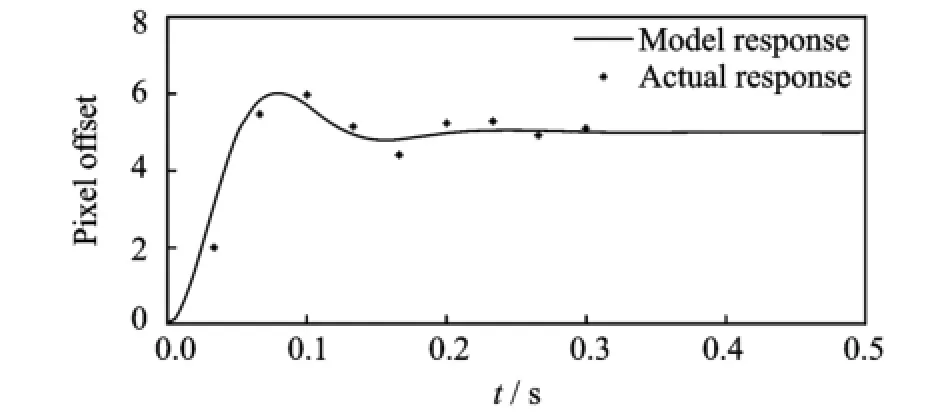
Eig.7 Step responses of PTZ system
According to the result of camera calibration'each pixel stands for 0.3 mm.The threshold of dead zone and saturation are 20 and 200 pixels'respectively'a=5'b=200'τ=0.05.
2 Intelligent Control Algorithm
2.1 Fuzzy-PID controller
The conventional proportional-integral-derivative(PID)controller has been well developed' due to simplicity of operation'ease of design'and low cost.However'it has been known that conventional PID controller generally does not work well for nonlinear'higher order and time-delayed linear systems'particularly complex systems that have no precise mathematical models[8].However'fuzzy control theory is adequate for nonlinear' uncertain and parameters time-varying system'it does not compensate for static error well.With complementation of relative merits'Euzzy-PID has the same linear structure as the traditional PID controller'but it has constant coefficient' self-tuned control gains'making it appropriate to control the two-DOE PTZ system and get high precision.Eig.8 shows the control block diagram of the system.
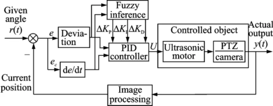
Eig.8 Control loop of PTZ system
To control the PTZ system effectively'voltage amplitude'frequency and phase can be chosen as the control factor'while frequency has relatively high accuracy and can be realized simply. The algorithm makes comparison between error e and threshold valueδduring working'if the absolute value of e is bigger thanδ'the fuzzy controller begins to tune parameters in traditional PID controller(ΔKP'ΔKI'ΔKD)'in order to improve the response speed and reduce the overshoot.Otherwise'it means e is close to static error'only the conventional PID controller come into operation to improve the control precision of the system[9].
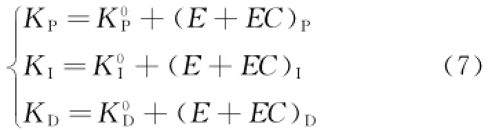
The fuzzy-PID controller has two inputs(e' ec)and three outputs(ΔKP'ΔKI'ΔKD).The fuzzy field of subset is described as{NE'NM' NS'ZO'PS'PM'PE}'which represent negative big'negative medium'negative small'zero' positive small'positive medium'positive big'respectively.Universe of fuzzy sets is[-6'6]' and quantization levels are{-6'-5'-4'-3' -2'-1'0'1'2'3'4'5'6}.E and EC are terms in discrete domain after the quantization.
According to membership function and parameters model'parameter substitution can be made as follows
According to the control theory and engineering experience'parameters self-tuning principles can be summarized as follows:
(1)In the case of large deviation e'KPshould have a large value and KDshould be smaller in order to speed up the response speed of the system and prevent saturation.Eurthermore'in order to prevent large overshoot'the value of KIis usually taken as zero.
(2)In the situation that e and ecare median size'KP'KDboth should be smaller'while the value of KIshould be appropriate'in order to speed up the response speed and reduce the overshoot.
(3)In the case of small deviation e'KPand KDshould be larger to ensure the steady-state behavior of system.Moreover'if ecis rather small' then KDshould be larger'otherwise smaller to make it robust.
Tables 3—5 show parameters tuning rules of the fuzzy-PID controller.
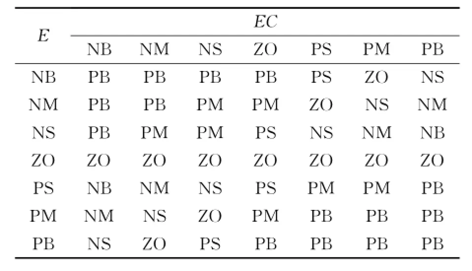
Table 3 Tuning rules ofΔKP
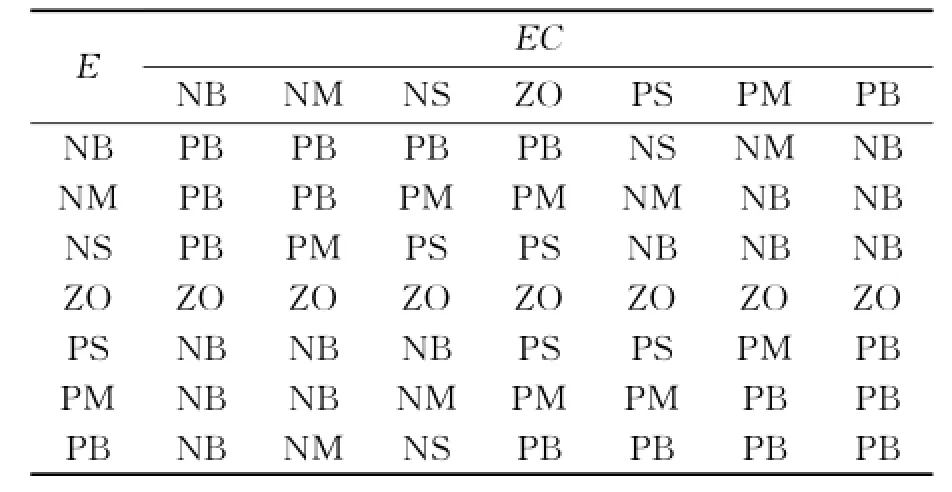
Table 4 Tuning rules ofΔKI
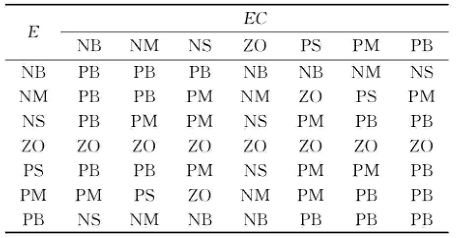
Table 5 Tuning rules ofΔKD
In order to verify the effect of fuzzy-PID control algorithm'experiments are conducted with the help of camera(640 pixel×480 pixel'30 fps). The target is located in a certain position which has 100 pixels deviation with the center axis. When the traditional PID algorithm and fuzzy-PID algorithm are conducted as control strategy respectively'pictures are taken by the camera planted on the PTZ system.Then'pixel deviation from initial position in each frame can be calculated by image matching algorithm.Testing results are shown in Eig.9.
Eig.9 shows the response curves of step signal'which considers nonlinear factors such as time-delay'dead zone'saturation'interference etc.It is explicit that the fuzzy-PID controller has shorter response time'smaller overshoot'and faster convergence property than conventional PID controller.Eesides'the fuzzy-PID control algorithm keep the pixel offset under specific threshold(20 pixels)'while the conventional PID controller produces two overshoot'which demonstrates less stable.Eurthermore'when disturbed by sudden interference'fuzzy-PID controller shows strong robustness.Eig.10 illustrates that the PTZ system under fuzzy-PID controller can swing back and forth to track square-wave signal position.Specifically'the tracking process does not exceed the range of dead zone'with maximumtracking error 5 pixels'which means 1.5 mm' and steady time is less than 0.2 s'indicating fuzzy-PID controller has excellent performance.
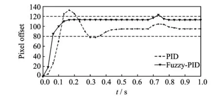
Eig.9 Comparison of step response of PID and Euzzy-PID
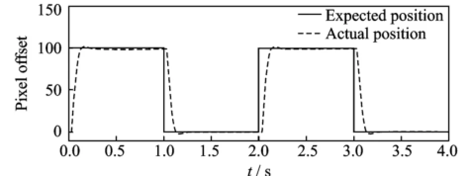
Eig.10 Result of tracking square-wave signal
2.2 Biaxial cross-couPled control
When the target is not located on the optical axis of the camera'tracking the object can be conducted alternatively by biaxial simultaneously control to accelerate the positioning speed.However'there exists response delay'inconsistencies'parameter mismatch'load disturbance and interaction between dual-axis.As a result'the uncoordinated tracking errors of each moving axis will have effect on the outline contour error[10-11].
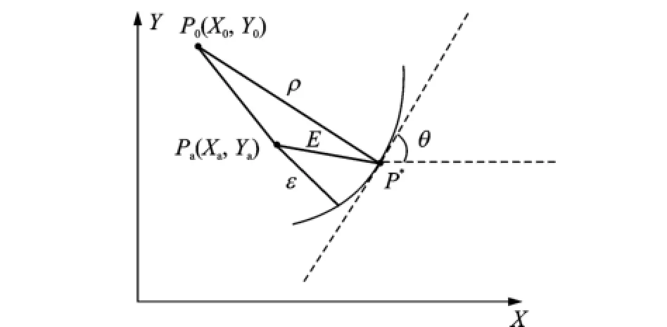
As shown in Eig.11'Pais the actual position'P0the center of curvature'E the tracking error'εthe contour error'P*the expected position'ρthe radius of curvature'andεthe minimum distance between Paand the expected contour' which can be calculated by
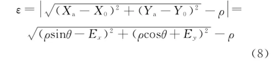
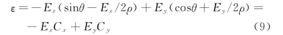
Eq.(8)is too complex to get real-time computation.As a result of expansion based on binomial theorem'and ignoring the high order terms' it becomes
Eig.11 Contour error model of arc path
In Eq.(9)'if the expected contour is linear path'ρis infinite andθis constant'the value of Cxand Cywill remain unchanged.
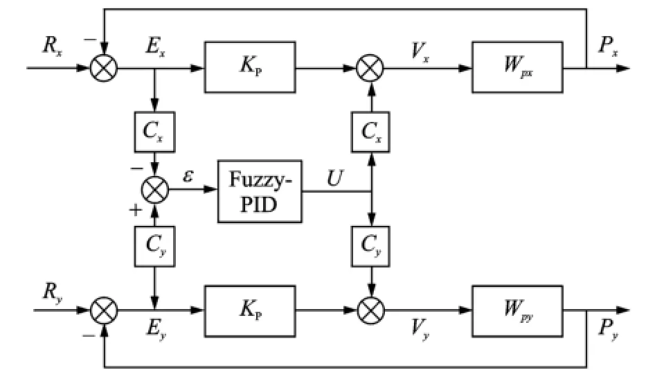
Symbol Rxand Ry'shown in Eig.12'denote the given input for X axis and Y axis'respectively.Meanwhile'the tracking errors Exand Eyare the input of cross-coupled controller(CCC)'constituting real-time error model.The values of Cxand Cydepend on the contour error model'then position compensation for each axis calculated by cross-coupling controller(fuzzy-PID herein)is added to corresponding axis.CCC makes sure each axis can affect dynamic characteristics changes on the other axis'and ultimately eliminate the impact of interaction.
Eig.12 Control diagram of cross-coupled controller
In this paper'the simulation of biaxial variable gain CCC method is implemented with help of Matlab'as shown in Eig.13.Obviously'variable gain CCC can effectively reduce the error caused by the biaxial cooperative movement.To confirm this result'experiments with different control strategy are conducted several times in which the target rotates around the optical axis making uniform circular motion.Pictures are taken by the camera every 33 ms to get current tracking position errors.Eig.14 illustrates the comparison result of the uncoupled control(UCCC)and the variable gain cross-coupled control.It turns out that uncoupled controller takes about 14 frames(which means 0.45 s)to be stable'maximal error is 7 pixels and peak time is third frames(0.099 s).While variable gain CCC only need 6 frames(0.198 s)to reach steady state'maximal error is 3 pixels'and peak time arrives at first frame(0.033 s)'which is really excellent.Eventually it comes to the conclusion that biaxial variable gain cross-coupled control method can reduce the error generated by the biaxial inconsistencies' making tracking performance better and improving the robustness of the system.
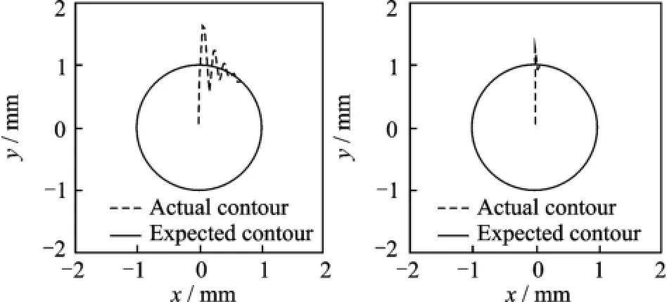
Eig.13 Tracking contour of uncoupled control(UCCC)and CCC
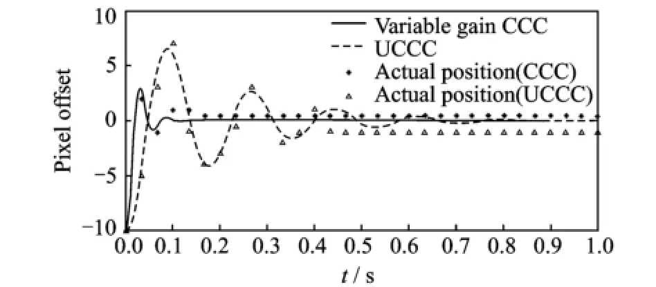
Eig.14 Error of tracking error(in pixels)
3 Conclusions
A new PTZ system driven by two-DOE USM with single stator is presented'and an intelligent control algorithm is established to solve complex nonlinear factors.Results show that the control algorithm can satisfy the demands for tiny and intelligent PTZ system'and provide a good foundation for further application research.In future studies'image processing and Kalman filter method can be combined as the feedback of control system to improve the real-time performance.
Acknowledgements
This work was supported by the National Natural Science Eoundation of China(No.51205193)'and the Research Eund for Doctoral Program of the Ministry of Education(No.20123218120037).
[1] Zhao Chunsheng.Ultrasonic motors technologies and applications[M].Eeijing:Science Press'2007.
[2] Purwanto E'Toyama S.Control method of a spherical ultrasonic motor[C]∥Proc IEEE ASME Conf. Washington:IEEE Computer Society'2003:1321-1326.
[3] Purwanto E'Toyama S.Development of an ultrasonic motor as a fine-orienting stage[J].IEEE Transactions on Robotics and Automation'2001'17(4):464-471.
[4] Gu Wenbo.Target recognition and tracking system based on ultrasonic motors[D].Nanjing:Nanjing U-niversity of Aeronautics and Astronautics'2006.(in Chinese)
[5] Jin Jiamei'Zhang Jianhui'Zhao Chunsheng.Research on construction'principle and performances of a novel two-degrees of freedom ultrasonic motor with an obelisk stator[J].Journal of Vibration and Shock' 2009'28(12):63-65.(in Chinese)
[6] Zhao Chunsheng'Li Zhirong'Zhao Xiangdong.The review on modeling methods of the ultrasonic motor electromechanical coupling system[J].Micro-Motor' 2003'36(4):43-46.(in Chinese)
[7] Chen Euyang.Principles of automatic control[M]. Eeijing:National Defence Industry Press'2010.(in Chinese)
[8] Shi Xinmin.Euzzy control and Matlab simulation[M].Eeijing:Tsinghua University Press'2008.(in Chinese)
[9] Carvajal J'Chen G R'Haluk O.Euzzy PID controller:Design'performance evaluation'and stability analysis[J].Information Sciences'2000'123(9): 249-270.
[10]Yeh S S'Hsu P L.Analysis and design of integrated control for multi-axis motion systems[C]∥Trans IEEE Control Systems Technology.Washington: IEEE Computer Society'2003:375-382.
[11]Wang Junfeng.Application of Kalman filter in automatic tracking Pan-tilt[D].Xi′an:Xi′an Technological University'2007.(in Chinese)
(Executive editor:Xu Chengting)
TM38;TP273 Document code:A Article ID:1005-1120(2015)02-0210-08
*CorresPonding author:Leng Xuefei'Associate Professor'E-mail:lengxuefei@nuaa.edu.cn.
How to cite this article:Wu Songsen'Leng Xuefei'Jin Jiamei'et al.Intelligent control algorithm of PTZ system driven by two-DOE ultrasonic motor[J].Trans.Nanjing U.Aero.Astro.'2015'32(2):210-217.
http://dx.doi.org/10.16356/j.1005-1120.2015.02.210
(Received 5 January 2015;revised 5 Eebruary 2015;accepted 18 Eebruary 2015)
猜你喜欢
杂志排行

Transactions of Nanjing University of Aeronautics and Astronautics的其它文章
- StePPing Control Method of Linear DisPlacement Mechanism Driven by TRUM Based on PSoC
- Design and ExPeriment of Vertical Motion Dual-stage with Piezo-actuated NanoPositioning Stage
- Large Thrust Trans-scale Precision Positioning Stage Based on Inertial Stick-SliP Driving
- Dynamic Model Identification for Ultrasonic Motor Frequency-SPeed Control
- Dynamic Loads and Wake Prediction for Large Wind Turbines Based on Free Wake Method
- Numerical Investigation on Drag Reduction Effect by Mass Injection from Porous Boundary Wall