Numerical Investigation on Drag Reduction Effect by Mass Injection from Porous Boundary Wall
2015-11-24ZhaoYong赵勇GaoYun高云JiangZongyu姜宗玉WangTianlin王天霖ZouLi邹丽
Zhao Yong(赵勇)'Gao Yun(高云)'Jiang Zongyu(姜宗玉)' Wang Tianlin(王天霖)'Zou Li(邹丽)
1.Transportation Equipment and Ocean Engineering College'Dalian Maritime University' Dalian 116026'P.R.China;
2.State Key Laboratory of Ocean Engineering'Shanghai Jiao Tong University'Shanghai 200240'P.R.China;
3.State Key Laboratory of Oil and Gas Reservoir Geology and Exploration'Southwest Petroleum University' Chengdu 610500'P.R.China;
4.Wood Group Mustang'Shanghai 201206'P.R.China;
5.School of Naval Architecture'Dalian University of Technology'Dalian 116024'P.R.China
Numerical Investigation on Drag Reduction Effect by Mass Injection from Porous Boundary Wall
Zhao Yong(赵勇)1'2'Gao Yun(高云)3*'Jiang Zongyu(姜宗玉)4' Wang Tianlin(王天霖)1'Zou Li(邹丽)5
1.Transportation Equipment and Ocean Engineering College'Dalian Maritime University' Dalian 116026'P.R.China;
2.State Key Laboratory of Ocean Engineering'Shanghai Jiao Tong University'Shanghai 200240'P.R.China;
3.State Key Laboratory of Oil and Gas Reservoir Geology and Exploration'Southwest Petroleum University' Chengdu 610500'P.R.China;
4.Wood Group Mustang'Shanghai 201206'P.R.China;
5.School of Naval Architecture'Dalian University of Technology'Dalian 116024'P.R.China
Interaction between the injected flow from the porous wall and the main flow can reduce drag effectively. The phenomenon is significant to the flight vehicle design.The intensive flux of injection enhances difficulty of numerical simulation and requires higher demands on the turbulence model.A turbulent boundary layer flow with mass injection through a porous wall governed by Reynolds averaged Navier-Stokers(RANS)equations is solved by using the Wilcox′s k-ωturbulence model and the obtained resistance coefficient agrees well with the experimental data.The results with and without mass injection are compared with other conditions unchanged.Velocity profile'turbulent kinetic energy and turbulent eddy viscosity are studied in these two cases.Results confirm that the boundary layer is blowing up and the turbulence is better developed with the aid of mass injection'which may explain the drag reduction theoretically.This numerical simulation may deepen our comprehension on this complex flow.
mass injection;boundary layer blowing up;drag reduction;turbulence model;Reyndds averaged Navier-Stokers(RANS)
0 Introduction
Elows through porous wall with mass injection'or termed as blowing'are encountered in many engineering applications such as boundary layer controlling'transpiration cooling and resistance reducing[1-3].The mass injection can impressively reduce resistance experienced by turbulent flow in pipes'and drag encountered by ships and airplanes'as well as the efficiency losses of turbines and turbo compressors[4-5].Thus turbulent boundary layer flow with mass injection has great engineering significance.Since the prediction of the effects of mass injection on slender aerodynamic body is of technological interest'several studies of boundary layers with mass injection have been carried out[6-7].An interesting aspect of the study of flows with mass injection is the phenomenon of boundary layer blow off[5].When the additional fluid is injected into a boundary layer'the injected fluid simply fills the region near the wall and significantly alters profiles of the flow variables.Due to the integration of the fluids near the wall'usual methods for handling twopoint boundary conditions would become invalid' especially when the blowing parameter is large[8].
This failure can be attributed to poor convergence and instabilities of the numerical methods[9].
Generally'the problem of porous wall with mass addition needs more attention to the drag reduction effect in engineering application'and on the other aspect'to understand the behavior of such complex flow.The simplest case is a turbulent boundary layer occurring on a flat plate at zero incidences.This flow model is'however'of great practical importance and it can be used in the calculation of the frictional resistance on ships'lifting surfaces'the blades of turbines and rotary compressors[6].Therefore'numerical work is taken to investigate the two-dimensional turbulent boundary layer flow over a smooth and permeable flat surface with mass injection.
1 Equations and Turbulence Model
Two-dimensional steady and incompressible boundary layer flow is governed by

where U'V are the stream-wise and normal averaged velocity components;ρ'P the fluid density and pressure;v'vTthe molecular and turbulent eddy kinetic viscosity.
Kolmogorov and Saffman creatively and independently developed the k-ωmodel.Wilcox has continually refined and improved the model during the past three decades and demonstrated its accuracy for a wide range of turbulent flows[10-12]. Here the latest version of k-ωmodel[12]is chosen' which considers the turbulent eddy viscosity[12]as follows

Reynolds stress for incompressible flow is

Turbulence kinetic energy equation is

Specific dissipation rate is

Closure coefficients and auxiliary relations are

where

It can be easily verified that the quantityχωis zero for two-dimensional flows.In the porous wall'the boundary condition is

On the contrary'the boundary condition of solid wall is non-slip'i.e.

Eor the model equation'the boundary condition is specified as

where d is the distance of the nearest grid to the wall.
2 Numerical Test
2.1 Flow Parameter
The flow parameters in the numerical calculation are listed in the following.Surface mass fluxis constant as 0.042 97 kg/(m2·s)' whereρwis the transpired air density and Vwthe normal velocity from the porous wall;Eree stream air velocity U∞is 9.397 m/s.Eoth the transpired and free stream air temperature T' densityρand pressure P are 297.8 K'1.193 kg/ m3'101 984 Pa'respectively.The schematic diagram of boundary layer with mass injection is shown in Eig.1.Air viscosity coefficient v is1.458×10-6'the length of the flat L=5 m'and the Reynolds number based on the free stream air velocity and flat length is 3.23×10⁷.

Eig.1 Eoundary layer with mass injection

2.2 Numerical method and mesh convergence validation
On the basis of laminar flow'we supplement codes of Wilcox′s k-ωmodel[12]to calculate the flow.Iterative algorithm is used to solve the equations'in the sequence of momentum equations'continuous equation and turbulence model equations.In the discrete equations'the secondorder upwind difference scheme is used for the convection term.The others are calculated by using the second-order central difference scheme. Uniform incoming velocity'free outflow'no-slip wall and zero normal gradient are defined for the boundary conditions'respectively.In order to check the convergence of meshes'three nested grids with nodes number of 301×101'151×51' 75×25 are used to discrete the computational zone with the dimension of 5 m×0.12 m.The frictional resistance coefficient along the plate is shown in Eig.2.It is shown that the numerical results are independent of the grid density.In the following calculation'the middle density grid'151×51'is selected.

Eig.2 Comparison of local frictional coefficient along the plate with three mesh density
Local frictional coefficient is compared with the experimental result'as shown in Eig.3.The numerical result is very close to the experimental result[13]'especially in the latter part of the wall. It clearly indicates the high precision of the numerical method.Therefore'Wilcox′s k-ω model[12]is suitable for turbulent boundary calculation with mass injection.
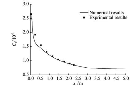
Eig.3 Comparison of local frictional coefficient along the plate between numerical and experimental results
2.3 Drag reduction analysis
To investigate the effect of mass injection on drag reduction'results with and without mass injection under the same condition are compared. The comparison of local frictional coefficient along the wall is shown in Eig.4.The resistance in solid case is almost four times more than that in porous case.We can discover impressive resistance reduction realized by mass injection.
The averaged stream wise velocity profiles of the two cases at x=1 m are shown in Eig.5.The velocity without mass injection develops much faster than that with mass injection'which leadsto a higher drag value.

Eig.4 Comparison of local frictional coefficient along the wall between results with and without mass injection

Eig.5 Comparison of average stream wise velocity profile at x=1 m
2.4 Turbulence quantities
Turbulent kinetic energy is directly proportional to turbulence development level'which is almost equal to zero in the zone of laminar flow. The contour lines of turbulent kinetic energy in the case with mass injection are shown in Eig.6. According to the turbulent kinetic energy distribution'the flow structure in the boundary layer flow is developed in the middle part of the layer.
Profiles of dimensionless turbulent kinetic energy at x=1 m in the cases with/without mass injection are shown in Eig.7.It is obvious that the flow is more turbulent in the case with mass injection.
Contour lines of ratio between eddy coefficient and molecular viscous coefficient in the case with mass injection are shown in Eig.8.The turbulent eddy coefficient is a key value in the Reynolds-averaged numerical simulation.Greater value indicates that turbulence is better developed' which is in consistent with the above analysis.

Eig.6 Contour lines of turbulent kinetic energy in the case with mass injection

Eig.7 Profiles of dimensionless turbulent kinetic energy at x=1 m

Eig.8 Contour lines of ratio between turbulent and molecular viscous coefficients in the case with mass injection
Profiles of dimensionless turbulent eddy viscous coefficient at x=1 m in the cases with/without mass injection are compared in Eig.9.The distance from the wall is normalized by boundarylayer nominal thickness.As shown in Eig.9'eddy viscosityμtwith mass injection is almost double the value without mass injection.

Eig.9 Profiles of dimensionless turbulent eddy coefficient at position of x=1 m
3 Conclusions
Numerical investigation is performed to study the drag reduction in two-dimensional turbulent boundary layer flows with mass injection through a porous wall.In this study'the Wilcox′s k-ω turbulence model[12]is employed.According to the comparison of numerical and experimental local frictional resistance coefficients'Wilcox′s k-ω model[12]seems to be able to predict the complex flow caused by mass injection with high precision. Numerical simulation shows that mass injection plays an active role in drag reduction by increasing the thickness of boundary layer.Meanwhile'turbulent kinetic energy and eddy viscosity are studied as well.The study also indicates that the turbulence flow is better developed with the aid of mass injection.
Acknowledgements
This work was supported by the National Natural Science Eoundation of China(Nos.51309040'51209027' 51379025'51379033)'the Open Research Eund of State Key Laboratory of Ocean Engineering(Shanghai Jiao Tong University'No.1402)'the Young Teachers Academic Program of SWPU(No.201499010114)'the Central Einancial Support of Local Key Discipline Youth Eund Project(YC319)'and the Eundamental Research Eund for the Central Universities(No.DMU3132015089).
[1] Gadelhak M'Eushnell D M.Status and outlook of flow separation control[R].AIAA Paper'1991:91-137.
[2] Eerdyugin A E'Eomin V M'Eomichev V P.Eody drag control in supersonic gas flows by injection of liquid jets[J].Journal of Applied Mechanics and Technical Physics'1995'36(5):675-681.
[3] Quadrio M'Eloryan J M'Luchini P.Effect of streamwise-periodic wall transpiration on turbulent friction drag[J].Journal of Eluid Mechanics'2007'576: 425-444.
[4] Ponnaiah S.Eoundary layer flow over a yawed cylinder with variable viscosity:Role of non-uniform double slot suction(injection)[J].Int J Numer Method H'2012'22(3):342-356.
[5] Sun R'Szwalek J'Sirviente A I.The effects of polymer solution preparation and injection on drag reduction[J].Journal of Eluids Engineering'Transactions of the ASME'2005'127(3):536-549.
[6] Kafoussias N'Xenos M.Numerical investigation of two dimensional turbulent boundary-layer compressible flow with adverse pressure gradient and heat and mass transfer[J].Acta Mech'2000'41:201-223.
[7] Akcay M'Yukselen M A.Elow of power-law fluids over a moving wedge surface with wall mass injection[J].Archive of Applied Mechanics'2011'81(1):65-76.
[8] Xu S X'Huang Y.The flow with mass transfer and longitudinal velocity on the wall[J].Acta Mechanica Sinica'2002'34(3):493-444.
[9] Vimalat C S'Nath G.Three dimensional laminar compressible boundary layers with large injection[J].J Eluid Mech'1975'71(4):711-727.
[10]Wilcox D C.Reassessment of the scale determining equation for advanced turbulence models[J].AIAA Journal'1988'26(11):1299-1310.
[11]Wilcox D C.Simulation of transition with a two equations turbulence model[J].AIAA Journal'1994'32(2):247-255.
[12]Wilcox D C.Turbulence modeling for CED[M].3rd Edition.La Canada CA:DCW Industries'Inc'2006.
[13]Andersen P S'Kays W M'Moffat R J.The turbulent boundary layer on a porous plate:An experimental study of the fluid mechanics for adverse freestream pressure gradients'H MT-15[R].Stanford' USA:Dept Mech Eng'Stanford Univ'1972.
(Executive editor:Xu Chengting)
O35 Document code:A Article ID:1005-1120(2015)02-0250-05
*CorresPonding author:Gao Yun'Lecturer'E-mail:dutgaoyun@163.com.
How to cite this article:Zhao Yong'Gao Yun'Jiang Zongyu'et al.Numerical investigation on drag reduction effect by mass injection from porous boundary wall[J].Trans.Nanjing U.Aero.Astro.'2015'32(2):250-254.
http://dx.doi.org/10.16356/j.1005-1120.2015.02.250
(Received 30 September 2014;revised 7 April 2015;accepted 12 April 2015)
猜你喜欢
杂志排行

Transactions of Nanjing University of Aeronautics and Astronautics的其它文章
- Dynamic Model Identification for Ultrasonic Motor Frequency-SPeed Control
- Design and ExPeriment of Vertical Motion Dual-stage with Piezo-actuated NanoPositioning Stage
- Large Thrust Trans-scale Precision Positioning Stage Based on Inertial Stick-SliP Driving
- Intelligent Control Algorithm of PTZ System Driven by Two-DOF Ultrasonic Motor
- Posture Adjustment of MicroPhone Based on Image Recognition in Automatic Welding System
- Dynamic Loads and Wake Prediction for Large Wind Turbines Based on Free Wake Method