StePPing Control Method of Linear DisPlacement Mechanism Driven by TRUM Based on PSoC
2015-11-24WangJunping王军平LiuWeidong刘卫东ZhuHua朱华LiYijun李亦君LiJianjun李建军
Wang Junping(王军平)'Liu Weidong(刘卫东)'Zhu Hua(朱华)*' Li Yijun(李亦君)'Li Jianjun(李建军)
1.School of Mechanical Engineering'Northwestern Polytechnical University'Xi′an 710072'P.R.China;
2.China Airborne Missile Academy'Luoyang 471009'P.R.China;
3.State Key Laboratory of Mechanics and Control of Mechanical Structures'Nanjing University of Aeronautics and Astronautics'Nanjing 210016'P.R.China
StePPing Control Method of Linear DisPlacement Mechanism Driven by TRUM Based on PSoC
Wang Junping(王军平)1'2'Liu Weidong(刘卫东)3'Zhu Hua(朱华)3*' Li Yijun(李亦君)2'Li Jianjun(李建军)2
1.School of Mechanical Engineering'Northwestern Polytechnical University'Xi′an 710072'P.R.China;
2.China Airborne Missile Academy'Luoyang 471009'P.R.China;
3.State Key Laboratory of Mechanics and Control of Mechanical Structures'Nanjing University of Aeronautics and Astronautics'Nanjing 210016'P.R.China
A method based on programmable system-on-chip(PSoC)is proposed to realize high resolution stepping motion control of liner displacement mechanism driven by traveling wave rotary ultrasonic motors(TRUM).Intelligent controller of stepping ultrasonic motor consists of PSoC microprocessor.Continuous square wave signal is sent out by the pulse width modulator(PWM)module inside PSoC'and converted into sinusoidal signal which is essential to the motor′s normal working by power amplifier circuit.Subsequently'signal impulse transmission is realized by the counter control break'and the stepping motion of linear displacement mechanism based on TRUM is achieved.Running status of the ultrasonic motor is controlled by an upper computer.Control command is sent to PSoC through serial communication circuit of RS-232.Relative program and control interface are written in Lab-View.Einally the mechanism is tested by XL-80 laser interferometer.Test results show that the mechanism can provide a stable motion and a fixed step pitch with the displacement resolution of 6 nm.
programmable system-on-chip(PSoC);ultrasonic motor;impulse transmission;upper computer
0 Introduction
The ultrasonic motor is a motor with a new working principle of the inverse piezoelectric effect of piezoelectric materials.Ey stimulating the elliptical motion of the medium particle contacts with the rotor(or slider)'the rotor(or slider)is driven to do rotary(or linear)motion by means of friction-driven[1].In the paper'a linear displacement mechanism is designed based on the traveling wave rotary ultrasonic motor(TRUM)' and the stepping motion control is a desired objective.
Under given stepping stimulation signals' the ultrasonic motor which runs specified number of steps according to the signals is called a stepping ultrasonic motor.Compared with the electromagnetic stepping motor'it has a simpler structure'easer for miniaturization'anti-electromagnetic interference'and it will be widly applied to optical instruments'robotics'space explorations'and medical equipments.There are mainly two ways for ultrasonic motors to achieve the step motion:(a)Special structure design'which often makes the step angle relatively large;(b)Drive control method.The design is to proceed from the drive control and lock the drive signal to be pulse excitation in order to give full play to the high-resolution characteristics of the ultrasonic motor'and to achieve small step angle'thus'the linear displacement mechanism of the ultrasonic motor can achieve small displacement resolution[2-4].
The realization of the above function relies on a powerful'highly integrated microprocessor programmable system-on-chip(PSoC)which is a microcontroller launched by Cypress.Its system can be configured and its architecture is shown in Eig. 1.It mainly composes of configurable analog modules[such as amplifiers'analog to digital converters(ADCs)'digital to analog converters(DACs)'filters and comparators]and configurable digital blocks[such as timers'counters'infra-red data association(IRDA)'pulse width modulations(PWMs)'shared port adapter(SPA)and universal asynchronous receiver transmitter(UART)].It also includes a fast 8-bit microprocessor'a flash memory of capacity up to 32 KE'2 KE of static random access memory(SRAM)'two 8×8 multiplier with 32-bit accumulator'power and sleep monitoring circuits' and hardware I2C communications circuit.The uniqueness of PSoC is that it provides an″analog +digital″mixed-signal configuration system. Single PSoC device can integrate as many as 100 peripheral components and microcontrollers'and save a lot of time for customers.The″analog+ digital″configurable PSoC maximize the flexibility of design'the synergy between them is the eternal theme in the development process of embedded system[5-6].
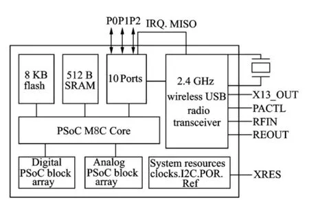
Eig.1 PSoC architecture
1 Linear DisPlacement Institutions Driven by Ultrasonic Motor
The working principle of the linear displacement mechanism is that the rotational movement of the ultrasonic motor is converted into linear movement of the actuator ejector rod with a ball screw connected to the ultrasonic motor output shaft[7].As shown in Eig.2'the linear displacement mechanism contains traveling wave type rotary ultrasonic motor'a nut guide seat'two flat keys'a ball screw and an ejector rod.The nut guide seat is fixed with ultrasonic motor with large screws and the output shaft of ultrasonic motor is connected with the ball screw shaft by a pivot pin.The inner wall of the nut-oriented block symmetrical open two keyways'two flat keys are installed in two keyways'the ball screw nut is limited in nut guide seat by the flat key and the ejector pin is fixed on the ball screw nut through small screws.The output shaft of ultrasonic motor drives ball screw shaft to rotate by shaft pin.The ball screw nut moves linearly along the axial of nut-oriented block under constraints of the flat key.The ejector pin driven by ball screw nut has a motion of linear reciprocating.

Eig.2 Linear displacement institutions
2 Working PrinciPle of Control System
Eig.3 is a schematic block diagram of a relatively mature control system for ultrasonic motor.It mainly consists of adjustable frequency generator'divider phase splitter and amplifier/ matching circuit[8-9].Erequency generator generates a frequency variable reference square wave signal;Phase splitter divides the square wave sig-nal on a reference frequency generates four time mutual difference of 90°;Amplifier/matching circuit then amplifies the signals to generate two sinusoidal signals with phase difference of 90°. These transformations are composed by a variety of integrated circuit components and the number of discrete capacitors'resistor elements.The control system composed this way the circuit board is relatively large because the number of components;And it is difficult to detect after a failure because the number of nodes is relatively large.
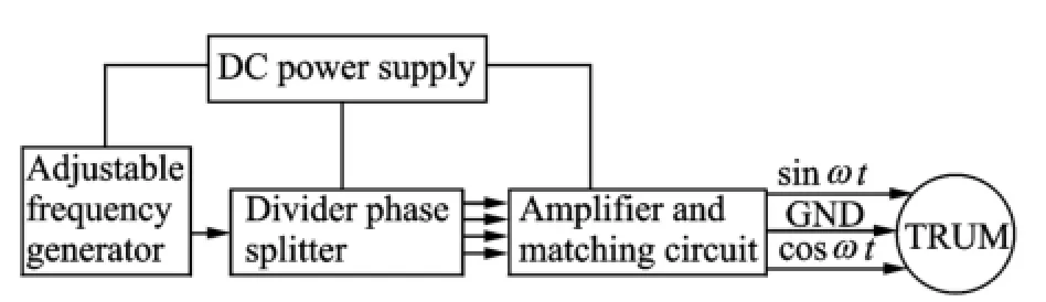
Eig.3 Elock of control system for ultrasonic motor
Eig.4 Circuit and prototype of ultrasonic motor drive
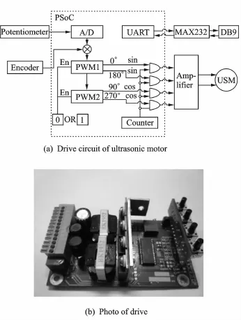
Eig.4(a)is a block diagram of an ultrasonic motor drive circuit whose core member is a PSoC.It can be seen the whole driver can complete various methods of control by a PSoC chip' such as eliminating the external need for the divider'phase shifting'inverting the integrated circuit components'greatly reducing the area of the control system circuit board'and improving the control system stability.PWMDE16(occupied by two PSoC module provides 16-bit resolution)is a 16-bit pulse width modulation module with a dead zone.Period register of PWMDE16 module determines the cycle of the PWM output frequency. Pulse width register determines the pulse width of the PWM output frequency.Dead time register determines time of the dead zone between the before/after edge of the two inverted signal P1and P2.The output of PWM module is an external interface circuit carried with CPU'it does not consume CPU resources at run-time.PSoC can also perform other work at the same time when the motor is running'such as detection'calculation and real-time control of the PWM generator to improve the real-time responsiveness and operational stability of ultrasonic motor[10].Eour square wave signals are generated by the PWMDE16 module'as shown in Eig.4(a)'wherein the two square-wave signals with a phase difference ofπgenerated by PWM1 directly drive MOSEET'and then they are converted into a sinusoidal signal via a push-pull inverter circuit.Correspondingly'two signals generated by PWM2 are converted into a cosine signal.Einally'the two phase difference ofπ/2'the same frequency'and the same amplitude alternating voltage are applied to the piezoelectric ceramic elements in the two groups of the ultrasonic motor driving its rotor to rotate.
The drive uses the frequency modulation(EM)speed control.The principle is that the resonance state of the stator can be controlled by adjusting the excitation frequency'thereby regulating the ultrasonic motor speed.A/D in Eig.4(a)is incremental type analog-to-digital converter' and it converts analog single of the potentiometer into digital single to regulate PWMDE16 module′s period variable.Thus'achieving the object of the EM speed control.Photo of the driv-er is shown in Eig.4(b).
3 Software ImPlementation of SteP Function
Steeping motion of the ultrasonic motor is the core of the paper.Communication between the host computer and the UART serial communication module built in PSoC is established with the help of MAX232 level converter chip.The number of pulses'the number of pulse groups' the group interval'the rotate speed and other relevant parameters are set in the control interface of the host computer to control the running status of ultrasonic motor.The stepping procedure block diagram is shown in Eig.5.Eirstly'all interrupt programs are stopped and the CPU registers with PSoC are initialized;Secondly'all interrupt programs'the timer and counter are opened.Appropriate judgments are conducted after receiving instructions from the host computer and entering the pulse mode.The number of pulses and group interval which control ultrasonic motor stepping motion are set by setting values of registers related with counter module of PSoC.Using Write-Compare Value function to modify the counter compare register value'its time length is corresponding to the number of the drive frequency cycles.WritePeriod function write cycle value to counter period register'the time counter outputs low level is the group interval.Counter will reduce the loaded period value to zero and produce a binary signal.On the one hand period value is reloaded;on the other hand the interrupt for PWDE16 module is obtained.Realization of the control of the number of groups depends on the timer and counter module.The timer′s period value is an integer multiple of the number of groups of counter.At the same time'the timer′s overflow interrupt mode is enabled.The counter is interrupted when it reaches the final count. Then'the counter is turned off in the interrupt program so as to realize the number control of group pulses.
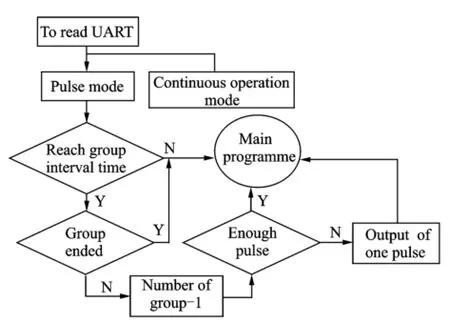
Eig.5 Elock of stepping program
4 ExPerimental Verification and Analysis
4.1 Test system
Since the displacement positioning resolution of the linear mechanism driven by the ultrasonic motor can reach micron grade or even nano scale' and the impact of environmental factors on the test results cannot be ignored'the trial sites select vibration isolation clean room at a constant temperature.The adopted test system is the XL-80 laser interferometer(Renishaw'UK)'which can provide 4 m/s maximum speed of measurement and 50 k Hz recording rate.Even at the highest data recording rate'the system accuracy can reach±0.5×10⁻⁶(linear mode)and a resolution of 1 nm'and meet the requirements of the test accuracy well.The entire system device is completed as shown in Eig.6'by fixing the optical lens of the laser interferometer measurement system'the compensation and the testing mechanism on a precision optical platform.
4.2 Test data
In order to check the stepping performance parameters of the drive'the waveform curves are tested under working conditions with different numbers of pulses.Eigs.7'8 show the output voltage waveforms of two different signals which go through the power metal oxide semiconductor(MOS)transistor gate and the filter capacitor with the input of 12 V DC power supply'wherethe frequency is approximately 40 k Hz.Two kinds of single group of 3-pulse signals are shown in Eig.7'while two kinds of single group of 5-pulse signals are shown in Eig.8.

Eig.6 Laser interferometer test system

Eig.7 Two kinds of single groups of 3-pulse signals
It can be seen from Eigs.7'8 that the waveform of drive in pulse form is stable and noise of ripple voltage is small.The gate voltage of the MOS transistor shocks after switched off'which is generated due to the high-frequency turn-off of power switch tube.The shock will be suppressed after going through the resonant circuit'which improves the efficiency and reliability of the circuit.
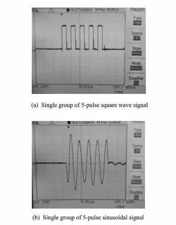
Eig.8 Two kinds of single groups of 5-pulse signals
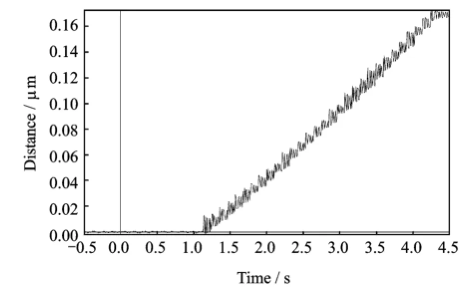
During actual test'signal is applied to the motor from the first pulse.The mechanism starts to respond when the number of pulse reaches 8. When the number of pulse reaches 10'the mechanism is basically becoming stable.This process is determined by the mechanical property of the system.Eig.9 shows the displacement response of ejector rod under the excitation of the 10-pulse signal'where the displacement resolution reaches about 6 nm.The fluctuation of the image after the response reflects a system shock'and the stabilization time is about 1.5 s.

Eig.9 Resolution test
Eig.10 Displacement response of pulse intermittently emission
Eig.10 is a displacement-time graph of the ejector rod under 30 groups of 10-pulse signals transmitted intermittently'where test system accuracy is 1 nm.The total stoke is about 0.18μm'which is 30 times of single group of 10-pulse signal.It can be seen from Eig.10 that the mechanism has a high repeated positioning accuracy and a smooth running process without any loss of synchronism.
5 Conclusions
Stepper drive control circuit based on PSoC microprocessor for linear displacement mechanism driven by rotation type ultrasonic motor is designed and laser displacement measurement test is conducted on the mechanism.The test results show that the drive circuit is stable.It is not only easy to control'but also highly sensitive.The mechanism has a stable stepping motion with a high positioning accuracy'achieving the desired control effect.Good stepping characteristics of the ultrasonic motor are beneficial to further expand the scope of its application.
Acknowledgements
This work was supported by the National Natural Science Eoundation of China(Nos.50905085'91116020)'the National Science Eoundation for Post-Doctoral Scientists of China(No.2012 M511263)'the Aviation Science Eoundation of China(No.20100112005).
[1] Ji Kehui'Guo Jifeng'Liu Xiao.Stepping characteristic of ultrasonic motor and its stepping-positioning control[J].Proceedings of the CSEE'2004'24(1): 71-75.(in Chinese)
[2] Zhao Chunsheng.Ultrasonic motors technologies and applications[M].Eeijing:Science'2007.(in Chinese)
[3] Zhao Chunsheng.Ultrasonic motor techniques in the 21st century[J].Journal of Vibration Measurement &Diagnosis'2000'20(1):7-12.(in Chinese)
[4] Zhao Chunsheng'Jin Jiamei.Standing wave frequency conversion stepping ultrasonic motor:China' 1688097[P].2005-10-26.(in Chinese)
[5] Dai Guojun'Zhang Xiang'Zeng Hong.Principle and application of single-chip microcomputer with configurable system[M].Eeijing:China Machine Press' 2009.(in Chinese)
[6] He Yongyi'Guo Shuai.Principle and application of system on chip of PSoC[M].Shanghai:Shanghai U-niversity Press'2003.(in Chinese)
[7] Zhou Zhihong'Wen Huaixing'Yang Dongsheng. Study on the installation method of ballscrews[J]. Manufacturing Technology&Machine Tool'2007' 29(6):140-141.(in Chinese)
[8] Wang Hongzhan.Research on ultrasonic motor driver based on PSoC[D].Nanjing:College of Aerospace Engineering'Nanjing University of Aeronautics and Astronautics'2009.(in Chinese)
[9] Han Tianjun'Liu Jianping'Li Chaodong.A drive and control circuit of ultrasonic motor based on DSP[J].Small&Special Electrical Machines'2003'31(3):30-34.(in Chinese)
[10]Gungor Eal'Erdal Eekiroglu'Sevki Demirbas'et al. Euzzy logic based DSP controlled servo position control for ultrasonic motor[J].Energy Conversion and Management'2004'45(20):3139-3153.
(Executive editor:Xu Chengting)
TM383.6 Document code:A Article ID:1005-1120(2015)02-0226-06
*CorresPonding author:Zhu Hua'Associate Researcher'E-mail:hzhu103@nuaa.edu.cn.
How to cite this article:Wang Junping'Liu Weidong'Zhu Hua'et al.Stepping control method of linear displacement mechanism driven by TRUM based on PSoC[J].Trans.Nanjing U.Aero.Astro.'2015'32(2):226-231.
http://dx.doi.org/10.16356/j.1005-1120.2015.02.226
(Received 15 October 2013;revised 16 December 2013;accepted 12 January 2014)
猜你喜欢
杂志排行

Transactions of Nanjing University of Aeronautics and Astronautics的其它文章
- Dynamic Model Identification for Ultrasonic Motor Frequency-SPeed Control
- Design and ExPeriment of Vertical Motion Dual-stage with Piezo-actuated NanoPositioning Stage
- Large Thrust Trans-scale Precision Positioning Stage Based on Inertial Stick-SliP Driving
- Intelligent Control Algorithm of PTZ System Driven by Two-DOF Ultrasonic Motor
- Dynamic Loads and Wake Prediction for Large Wind Turbines Based on Free Wake Method
- Numerical Investigation on Drag Reduction Effect by Mass Injection from Porous Boundary Wall