Structural Design and Control of Variable Camber Wing Driven by Ultrasonic Motors
2015-11-24LiuWeidong刘卫东ZhuHua朱华ZhouShengqiang周盛强EaiYalei白亚磊ZhaoChunsheng赵淳生
Liu Weidong(刘卫东)'Zhu Hua(朱华)'Zhou Shengqiang(周盛强)' Eai Yalei(白亚磊)'Zhao Chunsheng(赵淳生)
State Key Laboratory of Mechanics and Control of Mechanical Structures'Nanjing University of Aeronautics and Astronautics'Nanjing 210016'P.R.China
Structural Design and Control of Variable Camber Wing Driven by Ultrasonic Motors
Liu Weidong(刘卫东)'Zhu Hua(朱华)*'Zhou Shengqiang(周盛强)' Eai Yalei(白亚磊)'Zhao Chunsheng(赵淳生)
State Key Laboratory of Mechanics and Control of Mechanical Structures'Nanjing University of Aeronautics and Astronautics'Nanjing 210016'P.R.China
A novel variable camber wing driven by ultrasonic motors is proposed.Key techniques of distributed layout of drive mechanisms'coordination control of distributed ultrasonic motors as well as novel flexible skin undergoing one-dimensional morphing are studied.The system integration of small variable camber wing is achieved. Distributed layout of parallelogram linkages driven by geared ultrasonic motors is adopted for morphing'aimed at reducing the load for each motor and producing various aerodynamic configurations suitable for different flying states.Programmable system-on-chip(PSoC)is used to realize the coordination control of the distributed ultrasonic motors.All the morphing driving systems are assembled in the interior of the wing.The wing surface is covered with a novel smooth flexible skin in order to maintain wing shape and decrease the aerodynamic drag during morphing.Wind tunnel test shows that the variable camber wing can realize morphing under low speed flight condition.Lift and drag characteristics and aerodynamic efficiency of the wing are improved.Appropriate configurations can be selected to satisfy aerodynamic requirements of different flight conditions.The study provides a practical application of piezoelectric precision driving technology in flow control.
variable camber wing;ultrasonic motors(USMs);morphing skin;control system;wind tunnel test
0 Introduction
Aerodynamic performances'control characteristics can be improved and flight envelopes can be expanded through active deformations of morphing aircrafts.Various flight demands can be achieved by increasing the lift'reducing the drag' extending the range'and suppressing the flutter[1-2].
As the wing is the main source of the lift of aircraft'most researches concentrate on the morphing wing design.At the beginning of the 21st century'Defense advanced research projects agency(DARPA)started to research on morphing techniques of trailing edge based on smart materials.Active flexible wing was assembled on E/A-18.Traditional leading edge flap and trailing edge aileron were adopted to make the wing twist. Wind tunnel test shows that precisely transformation of the wing shape can considerably reduce aerodynamic drag and transonic shock wave[3-4]. The approach also demonstrates that flexibility of the wing can be used to improve aerodynamic performance of the wing.However'the approach mainly concentrates on the traditional morphing technology.With the rapid development of smart materials recently'newly developed actuators based on smart materials should be taken into consideration in the design of morphing wings.
National aeronautics and space administration(NASA)and DARPA are focusing on developing novel tailless smart aircraft.Several design proposals based on electroactive polymer'piezoelectric/hydraulic pump'shape memory alloy(SMA)and ultrasonic motor(USM)are studied. USM is a motor with a new working principle of the inverse piezoelectric effect of piezoelectric materials.Ey stimulating the elliptical motion of the medium particle contacts with the rotor(or slider)'the rotor(or slider)is driven to do rotary(or linear)motion by means of friction-driven.It is pointed out that power density of USM is superior to other actuators and the effect of distributed driving is better than traditional drive mode[5-7].In face'in 1998'Wlezien'et al.at Langley proposed that piezoelectric actuator was the best choice for morphing aircraft'except the disadvantage of small deformation of the piezoelectric element[8].The drawback can be settled by USM because it can amplify the high-frequency micro-amplitude vibration of the piezoceramics.The new conceptual motor is now developing rapidly and applied to the aerospace field[9-10].
As described by Thill'et al.'a morphing skin can be envisaged as an aerodynamic fairing to cover an underlying morphing structure and transfer aerodynamic loads of the morphing wing. Therefore'flexible skin becomes one of the key technologies of morphing aircraft[11].Tomohiro' et al.proposed an out-of-plane corrugated flexible skin structure manufactured from carbon fiber plain woven fabrics[12].Olympio'et al.studied 0-Poisson′s ratio honeycombed structures'the hybrid and accordion honeycomb.The two are also designed for one-dimensional morphing and can be easily manufactured by water jet cutting[13]. Gandhi'et al.proposed some design considerations for flexible skins.It is significant that the skins must have low in-plane stiffness to minimize actuation energy[14].The lower the in-plane stiffness of the structure is'the less energy the morphing consumes.Therefore'structure with lower stiffness in the morphing direction should be developed to constitute a more efficiency flexible skin.
With the same dimension in small scale'the output drive power of USM is larger than electromagnetic motor[6].In the paper'a feasible application technology of USM is proposed and a new kind of small variable camber wing driven by USMs is designed.Distributed layout of parallelogram linkages is adopted to transmit the rotation from the geared USMs to the trailing edge'so as to realize the function of variable camber.A new kind of flexible cosine honeycombed skin is designed to maintain aerodynamic shape of the wing.The working principle and design procedures of the wing will be discussed.Einally'the corresponding aerodynamic performances of seven typical aerodynamic shapes of the wing will be presented which are obtained by wind tunnel test.
1 ConcePtual Model
Small rectangular wing for small unmanned aerial vehicle(SUAV)is chosen as the design object.Considering the low speed flying characteristics of SUAV and installation dimensions of the driving mechanisms'NACA23018 which has a relatively large thickness and is suitable for low speed aircraft wing is adopted as the airfoil for the wing.Wing parameters are listed in Table 1.

Table 1 Wing Parameters
As shown in Eig.1'double spar type structure is applied to the whole wing.The front spar is arranged at the location of 25%chord length' and the drivers for the actuators are assembled on it.The rear spar is positioned at 53%chord length.The wing is assumed to be divided into several equal segments along spanwise direction and USMs are aligned at equal spacing on the rear spar in a distributed way.The number of USMs will be determined by the torque required by morphing and aerodynamic loads.The corresponding rib tips are driven by actuators respectively.To ensure that the whole trailing edge deform smoothly'two flexible carbon sticks are arranged along the spanwise direction in the interior of the trailing edge.In addition'small wing rib tips areadded to the trailing edge to maintain the airfoil' so the trailing edge can obtain continuous appearance during rotating or twisting deflections.

Eig.1 Conceptual wing structure
2 Methods
2.1 Drive mechanism for morPhing
To assemble the USMs in the interior as well as realize large deformation of the wing'parallelogram mechanisms driven by distributed geared USMs are adopted in each segment of the wing to drive the trailing edge'as shown in Eig.2.Compared with existing morphing methods'this kind of drive mechanism is simple and reliable'and can be easily manufactured and integrated into the whole system.The output shaft of geared motor is assembled in Hole 1 to supply the driving torque for the whole mechanism.The angular displacement transducer is located at Hole 2 to provide real-time feedback for the control system. Although the trailing edge can be driven by the linkages to have a deflection range of more than ±20°'a deflection range of±10°is selected as a verification test in this study.
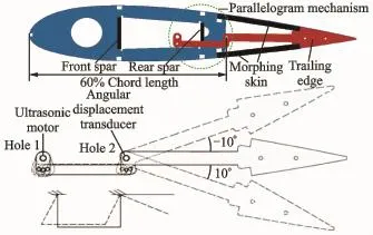
Eig.2 Parallelogram mechanism
2.2 High elastic telescoPe skin
The 60%to 80%of the chord is designed to be flexible section of the wing.Taking the airfoil whose chord length is 1 as an example'the lengths of the morphing parts of the top and bottom surfaces of the airfoil are obtained by interpolation method and listed in Table 2 when the trailing edge deflects up and down smoothly.In Table 2'the biggest strain of 3.8%exists on the top of the airfoil when the trailing edge deflects downward to 10°.
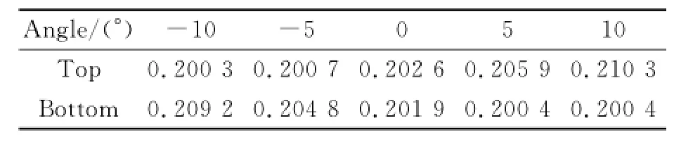
Table 2 Length of toP and bottom surfaces of morPhing section of unit-chord airfoil
Elexible skin for variable camber wing requires light weight'high flexibility for in-plane morphing and large bending stiffness to afford aerodynamic pressure.Coreless semi-rigid skin is proposed to satisfy the mentioned requirements. Elastic structure with high flexibility in morphing direction works as a support to help the skin resist the normal pressure on the surface.A smooth silastic film is covered on the structure to reduce the aerodynamic drag.
The length of the flexible skin in morphing direction is calculated to be 63.819 mm.The whole length is finally set to be 80 mm considering the assembly of the elastic structure.The deformation part is 63 mm'and each of the two supports is 8.5 mm.Polyoxymethylene(POM)' a kind of plastic whose elastic modulus is about 1.7 GPa'is adopted to manufacture this structure.The elastic structure is designed to be a cosine type honeycomb which is appropriate for stretching.Three longitudinal beams are inserted to strengthen the stiffness in nondeformable directions.Sample of the elastic structure is manufactured'as shown in Eig.3.

Eig.3 Sample of elastic structure
Einite element(EE)model and test of the sample are shown in Eig.4.The result of the finite element analysis shows that the stiffness in X direction of the cosine honeycomb is only 0.187 MPa.It is just 1.1×10⁻⁴of the raw material′s stiffness'which consists well with test result.Therefore'a distributed force of 27.6 N/m is required to apply on right edge of the structure to obtain the strain of 3.8%.

Eig.4 EEM and test of sample
2.3 Performance of USMs
Assume that the two flexible carbon sticks inserted in the trailing edge has very fine diameters and has little contribution to the drive mechanisms'the drive mechanisms have to conquer three resisting torques.Therefore'the total torque required by the mechanisms is

where Mteis the aerodynamic torque of the trailing edge'Mmsthe torque for flexible skin morphing'and Mfthe torque results from frictions of the mechanisms.
Aerodynamic torque of the trailing edge can be calculated as follows
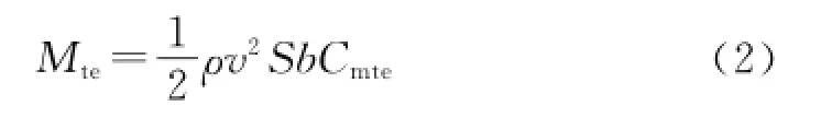
whereρv2is the dynamic pressure'S the wing area'b the span of the wing'and Cmtethe torque coefficient of the trailing edge.And Cmtecan be obtained by aerodynamic calculation.
The torque for skin morphing can be approximately calculated as follows
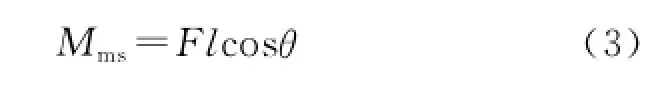
where F is the tension or compression required by deformed skin'and l cosθthe corresponding arm of force.
The torque results from frictions can be calculated by structure dynamic simulation.
Supposing the cruising speed is 0.2Ma'the angle of attack is 2°.Considering the maximum morphing state of the wing'the trailing edge deflects down to 10°.Three resisting torques can be obtained respectively and the total torque required by the mechanisms is figured out to be 4.274 N· m.
Considering space limitations'speed and torque requirements'USM40 with the external diameter of 40 mm and the rated torque of 0.15 N·m is adopted here.Main technique data of the motor are listed in Table 3.

Table 3 SPecifications of USM40
As mentioned by Kudva'a minimum actuation rate of 25°flap deflection in 0.33 s'producing a slew rate of 75°/s'is desired of morphing wing[5].In order to slow down the rotation speed and increase the torque of the parallelogram linkages'gear transmission with a reduction ratio of 1∶10 is assembled between the motor and the linkage.Then the rotation speed decreases to 75°/s and the drive torque increaseas to 1.5 N·m.5 geared USMs can totally provide a drive torque of 7.5 N·m and satisfy the torque requirement.
2.4 Control system
Programmable system-on-chip(PSoC)isadopted to realize the coordination control of the distributed USMs.Elock diagram of the driver circuit based on PSoC for USMs is shown in Eig.5.The driver and upper computer control interface are realized in C++.In each segment of the wing'the change of the angle of the trailing edge is detected and sent back to the control system by the angular displacement transducer.In addition'two limit switches are assembled to control the deflection range of the trailing edge.

Eig.5 Driver circuit of USMs
2.5 PrototyPe of wing
A prototype of the variable camber wing is manufactured'as shown in Eig.6.The spars and ribs of the wing are made of aluminum.Due to self-lock of USM'there is no need to use additional self-lock devices.The drive mechanisms and control system'including mechanical structures and electronic components'are all assembled in the interior of the wing.The leading edge'which is invariable'is covered with heat shrinkable skin.The morphing part of the wing is covered with the flexible skin mentioned above. Thus the wing can obtain a gapless configuration.

Eig.6 Prototype of wing without skin
3 Wind Tunnel Test
Wind tunnel test is conducted in a low speed wind tunnel in Nanjing University of Aeronautics and Astronautics'as shown in Eig.7.The measuring system concludes a strain-gauge balance with six components'signal amplifier for the balance'data acquisition card and the processing software.The measuring range of the balance is 3 kg and the test accuracy is 0.5%.The wind speed is set to be 20 m/s.Reynolds number is 4.3×10⁵.
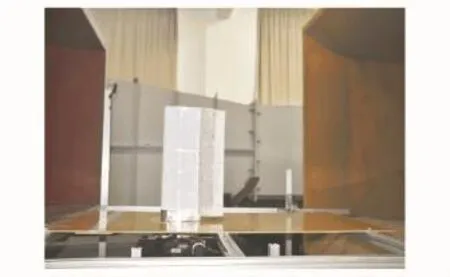
Eig.7 Wind tunnel test of morphing wing
The variable camber wing can realize various shapes due to its flexible trailing edge and the distributed driving mechanism.Seven typical shapes(as shown in Eig.8)are selected to study the aerodynamic characteristics.The lift and drag forces of the seven typical shapes are measured when the angle of attack changes from-6°to 28°.
4 Result and Discussion
Eig.9 shows the coefficients of lift of mentioned seven typical shapes versus different angles of attack.In Eig.9'the maximum lift coefficients exist when the trailing edge deflects downward to 10°(which is the shape in Eig.8(b))'while the minimum lift coefficients can be obtained when the trailing edge deflects upward to-10°(which is the shape in Eig.8(c)).The lift coefficients of the shape in Eig.8(c)are 57.9%larger than the shape in Eig.8(b)on average.Other configurations obtain lift coefficients between them.The more the trailing edge deflects down'the larger lift coefficient will be obtained.It can be seenclearly that the variable camber wing can remarkably change its lift characteristics.

Eig.8 Seven typical shapes of wing

Eig.9 Coefficients of lift of seven typical shapes v.s. different angles of attack
Eig.10 shows the lift-to-drag ratios of seven typical shapes versus different angles of attack.It is clear that the wing shapes with different cambers have distinguishable effects on the lift-todrag ratio of the wing and can be adopted under different flight conditions.Raising the lift-to-drag ratio can reduce flight consumption.Therefore' choosing the best wing shape under certain flight condition can effectively raise flight efficiency. Eor the angles of attack of-6°to 3°'the shape in Eig.8(b)gets the largest lift-to-drag ratio'and the shape is suitable for landing and cruising.Eor the angles of attack of 3°to 5°'the shape in Eig.8(f)is the best choice and the shape is suitable for taking off.

Eig.10 Lift-to-drag ratios of seven typical shapes v.s. different angles of attack
5 Conclusions
A new type of variable camber wing based on USMs is designed and manufactured.Distributed layout of driving mechanisms can reduce torque requirement for each motor and realize various wing shapes.USM40 is selected as the best actuator for the wing considering certain morphing requirements.Coordination control of distributed USMs is realized based on PSoC.A coreless semi-rigid skin which is suitable for morphing wing is proposed and studied.Prototype of the wing is manufactured and aerodynamic test is done in a low speed wind tunnel.Results show that the wing can realize expected morphing under low speed flight conditions.
Seven typical aerodynamic shapes are proposed of which the aerodynamic performances are considerably different from each other.It can be seen from wind tunnel test results that compared with traditional invariable camber wings'the variable camber wing can provide appropriate wing shapes for various flight conditions which can help to obtain a better aerodynamic performance.
The exploratory work of variable camber wing driven by USMs synthesizes multi-disciplinary problems.Aerodynamic performance'mechanical design'material selection and drive and control system design have to be taken into consideration simultaneously.The study demonstrates that USMs can be used as actuators for global deformation of small morphing wings ofSUAV.Due to its outstanding characteristics'it can hopefully be adopted for local flow control for larger aircrafts.
Acknowledgements
This work was supported by the National Natural Science Eoundation of China(Nos.50905085'91116020)'the Aviation Science Eoundation of China(No.20100112005).
[1] Weisshaar T A.Morphing aircraft technology-new shapes for aircraft design[R].RTO-MP-AVT-141. Erance:NATD Science and Technology Orgnization' 2006.
[2] Justin E M.Analysis and design of a hyper-elliptical cambered span morphing aircraft wing[D].New York:Cornell University Graduate School'2006.
[3] Hans P M.Realization of an optimized wing camber by using form variable flap structures[J].Aerospace Science and Technology'2001'5(7):445-455.
[4] Reed Jr J L'Hemmelgarn C D'Pelley E M'et al. Adaptive wing structures[C]//Proceedings SPIE' Smart Structures and Materials 2005:Industrial and Commercial Applications of Smart Structures Technologies.San Diego'CA:SPIE'2005'5762:132-142.
[5] Kudva J N.Overview of the DARPA smart wing project[J].Journal of Intelligent Material Systems and Structures'2004'15(4):261-269.
[6] Jonathan D'Eartley C.Development of high-rate'adaptive trailing edge control surface for the smart wing phase 2 wind tunnel model[J].Journal of Intelligence Material Systems and Structures'2004'15(4):279-292.
[7] Loewy R L.Recent developments in smart structures with aeronautical applications[J].Smart Materials and Structures'1997'6(5):R11-R42.
[8] Wlezien R W'Horner G C'Mc Gowan A R'et al. The aircraft morphing program[R].AIAA 98-1927' 1998.
[9] Zhao Chunsheng.Ultrasonic motors technologies and applications[M].Eeijing:Science Press'2007:1-19.(in Chinese)
[10]Zhu Hua'Liu Weidong'Zhao Chunsheng.Morphing aircraft and its morph-driving techniques[J].Machine Euilding Automation'2010'39(2):8-14'125.(in Chinese)
[11]Thill C'Etches J'Eond I'et al.Morphing skins[J]. Aeronautical Journal'2008'112(1129):117-139.
[12]Tomohiro Y'Shin-ichi T'Toshio O'et al.Mechanical properties of corrugated composites for candidate materials of flexible wing structures[J].Composites Part A:Applied Science and Manufacturing'2006'37(10):1578-1586.
[13]Olympio K R'Gandhi E.Zero Poisson′s ratio cellular honeycombs for flex skins undergoing one-dimensional morphing[J].Journal of Intelligent Material Systems and Structures'2010'21(17):1737-1753.
[14]Gandhi E'Anusonti-Inthra P.Skin design studies for variable camber morphing airfoils[J].Smart Materials and Structures'2008'17(1):015025-015033.
(Executive editor:Xu Chengting)
V11 Document code:A Article ID:1005-1120(2015)02-0180-07
*CorresPonding author:Zhu Hua'Associate Researcher'E-mail:hzhu103@nuaa.edu.cn.
How to cite this article:Liu Weidong'Zhu Hua'Zhou Shengqiang'et al.Structural design and control of variable camber wing driven by ultrasonic motors[J].Trans.Nanjing U.Aero.Astro.'2015'32(2):180-186.
http://dx.doi.org/10.16356/j.1005-1120.2015.02.180
(Received 18 September 2013;revised 2 January 2014;accepted 12 January 2014)
杂志排行

Transactions of Nanjing University of Aeronautics and Astronautics的其它文章
- StePPing Control Method of Linear DisPlacement Mechanism Driven by TRUM Based on PSoC
- Large Thrust Trans-scale Precision Positioning Stage Based on Inertial Stick-SliP Driving
- Intelligent Control Algorithm of PTZ System Driven by Two-DOF Ultrasonic Motor
- Dynamic Model Identification for Ultrasonic Motor Frequency-SPeed Control
- Dynamic Loads and Wake Prediction for Large Wind Turbines Based on Free Wake Method
- Numerical Investigation on Drag Reduction Effect by Mass Injection from Porous Boundary Wall