Friction Behavior on Contact Interface of Linear Ultrasonic Motor with Hard Contact Materials
2015-11-24WangJinpeng王金鹏ZhouHongping周宏平JinJiamei金家楣ZhaoChunsheng赵淳生
Wang Jinpeng(王金鹏)'Zhou Hongping(周宏平)'Jin Jiamei(金家楣)' Zhao Chunsheng(赵淳生)
Friction Behavior on Contact Interface of Linear Ultrasonic Motor with Hard Contact Materials
Wang Jinpeng(王金鹏)1*'Zhou Hongping(周宏平)1'Jin Jiamei(金家楣)2' Zhao Chunsheng(赵淳生)2
1.College of Mechanical and Electronic Engineering'Nanjing Eorestry University'Nanjing 210037'P.R.China;
2.State Key Laboratory of Mechanics and Control of Mechanical Structure'Nanjing University of Aeronautics and Astronautics'Nanjing 210016'P.R.China
How to improve the efficiency of the linear ultrasonic motor with hard contact materials(HLUSM)or the precision motion stage driven by HLUSM'becomes a hot issue.Analysis and testing of friction behavior on the contact interface of HLUSM is one of the key issues.Under the action of ultrasonic vibration and impact'the friction behavior on contact interface is very complex due to micro-amplitude and high frequency.Moreover'it is difficult to observe and test it.Eocusing on the frictional behavior on the interface of HLUSM'a new method'through testing the vibration of the driving tips(scanning vibrometer PSV-400-3D)and the motion of the slider(displacement sensor LK-G30)'respectively'is proposed.Then'take the HLUSM as an example'theoretical analyses and experiments are carried out.Theoretical analysis shows that the average speed of the slider should be 600 mm/s when there is no slippage between the stator and slider during the contact process.Experimental results show that the average speed of the slider is about 390 mm/s.At the same time'the tangential vibration speed of the driving tip of HLUSM is larger than 600 mm/s.Therefore'there must be slippage between the stator and slider of HLUSM.Eurther experimental results show that the maximum efficiency is less than 10%.The slippage on the contact interface should be the main reason for the low efficiency of HLUSM.
friction behavior;ultrasonic vibration;slippage;efficiency
0 Introduction
Hard contact materials'such as AL2O3/Zr O ceramics'is widely used to reduce the effect on positioning accuracy by the deformation of the contact interface'and improve motion accuracy and lifetime of the linear ultrasonic motor(LUSM).The friction on the contact interface is the main reason of structural energy dissipation. Under the action of micro-amplitude vibration with ultrasonic frequency'the friction behavior on the ceramics contact interface(AL2O3-Zr O)is very complex.Research on the microscopic friction behavior on the contact interface is a basic work to reveal the mechanisms of the energy transfer and dissipation of the linear ultrasonic motor with hard contact materials(HLUSM)under ultrasonic vibration.Certainly'the energy transfer and dissipation on the interface are very closely related to the efficiency of HLUSM.
There are two different situations about the friction characteristics under the action of ultrasonic vibration and impact.One is associated with the contact model of the travelling wave rotary ultrasonic motor[1-3].The other is about the contact problem of LUSM[4'5].Most of the existing studies assume that only the static friction exists on the contact interface.Twiefel et al.established an experimental platform to investigate the normal direction high-frequency impact process'andone special circuit was used to measure the contact duration[6].Then'for the three contact conditions of linear standing wave ultrasonic motors' stick'slip and separation'an elementary piecewise linear model was proposed and solved with semi-analytical method[7].However'these studies are still not sufficient to understand the fundamentals of the friction behavior on the contact interface.The transmitting model of ultrasonic vibration in ultrasonic transducer and capillary were studied in the ultrasonic bonding progress[8].The microscopic vibration locus and the relationship between ultrasonic vibration energy density and the section area were studied.Recently'the vibration of stator′s center of mass and the friction of stator and slider were studied[9].
This paper focuses on the study of the interfacial microscopic friction behavior of HLUSM. Eurthermore'the energy transfer efficiency issues are also studied.
1 Performance and Friction
1.1 Performance of HLUSM
The butterfly-shape LUSM is a good choice for the precision positioning stage for its high thrust and speed.Shi Yunlai et al.[10]conducted a lot of optimal design works of butterfly-shaped LUSM.However'the contact state and friction behavior of HLUSM on the contact interface may be very different.Therefore'an experiment is conducted with the help of XL-80 laser interferometer.Mass of the slider is 0.594 kg'and the optical assembly fixed on the slider is 0.371 kg. There is no-load along the direction of movement.The experimental results show that the speed of the slider is a long rising process.It costs about 100 ms before reaching steady state. As shown in Eig.1'the maximum speed is less than 420 mm/s'although the slider can reach the steady state during the stroke of 60 mm.The results indicate that the wear and tear on the contact interface are serious'and the energy transfer efficiency is very low.Therefore'further research on the interfacial friction behavior of HLUSM is necessary.
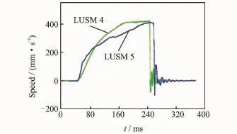
Eig.1 Experimental curves of slider′s speed of HLUSM(Driving frequency:50 k Hz'prepressure:40 N)
1.2 Theoretical analysis of friction behavior on contact interface
According to the research on HLUSM'we take the butterfly-shape HLUSM as only one driving tip to analyze its characteristics in theory. Then'the pressure between the stator and slider is equal to value shown on the pressure monitor.
When HLUSM is working in steady state' the ideal elliptical track of the driving tip is shown in Eig.2.It can be seen that'moving trajectory of the driving tip is an ellipse which can be divided into two components in tangential(x)and normal(y)direction.The center of the ellipse is defined as the original point O of the coordinate system. The driving tip of stator comes into contact with the slider from t0to t1and pushes the slider forward in x-direction by friction force.Then'they are separated'the slider moves continuously in an attenuated mode'the stator remain idle until they come into contact again(t0′).
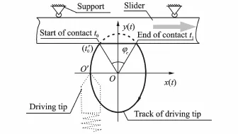
Eig.2 Ideal elliptical track of driving tip of HLUSM
Taking the slider as the analysis target when HLUSM works in steady state and assuming the friction force between the slider and its lead railcan be ignored'the schematic is shown in Eig.3. In the normal direction'the contact force Fcis equal to the structure constraint force Fr.Obviously'Fcis relevant to the pre-pressure F0and the amplitude of the driving tip of HLUSM.In the tangential direction'the driving force Fτshould be equal to the sum of the load Fland the velocity-dependent viscous friction force Fv.At steady state'the speed of slider is higher than that at transient state.

Eig.3 Dynamic model of slider
Assuming that there is no slippage between the stator and slider during the contact process' we can get the maximum speed or efficiency of HLUSM.Moreover'to simplify the problem' only the pre-pressure F0is taken into account. Thus'the driving force is equal to the tangential static friction force.The following two equations can be abtained according to the Coulomb friction law.

whereμsis the static friction coefficient between the driving tip and slider.Moreover

Then'the following equation can be derived as

According to the practical experience'the values of c'μs'F0and Flare set as 0.1 m/s' 0.08'40 N and 1.96 N.Therefore'is 12.4 m/s.It is much larger than the above experimental results.Then'we recalculate it by using another method.
According to Newton′s second law of motion'the slider′s movement can be described as[11]
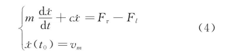
where˙x is the velocity of slider'm the mass of the slider'c the damping coefficient of slider'and vmthe average speed of the slider.
The slider speed in the moment t1can be calculated as[12]
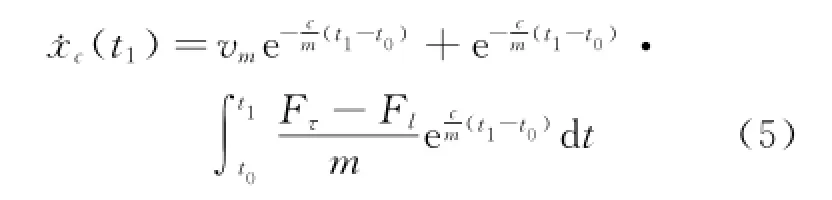
Then'the average speed of slider in separation period t1<t<t0'is
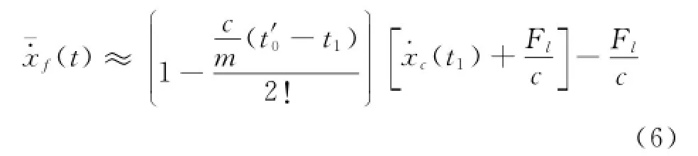
Eq.(6)indicates that the slider′s speed at the separation moment and duration of separation are two vital factors affecting the steady speed of HLSUM.Then'the speed difference after the driving cycle is
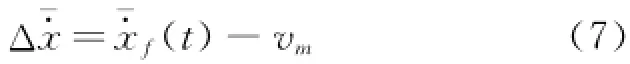
Eq.(7)shows that how much energy the slider gets from the stator in one driving cycle.
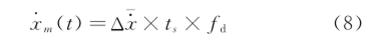
If t0is defined as the starting point of one steady state driving cycle'fdis the frequency of driving signals't1can be expressed as(2fd)-1when we assume thatφcis 180°(Eig.2)'and parameter t0'is expressed as.Einally'can be calculated with these parameters given in Table 1.It is 200.03 mm/s when these parameters are set as the values of the second column in Table 1 andis 0.03 mm/s.Then'if Flis changed to 0.22×9.8 N(third column in Table 1)'is 200.02 mm/s.Moreover'if vmis assumed as 400 mm/s'will be 0.025 mm/s.It is obvious thathas not changed too much in soshort period time even though vmor Flis changed.Therefore'we can deduce the steady speed of slider withΔx-·and the movement time(ts)as
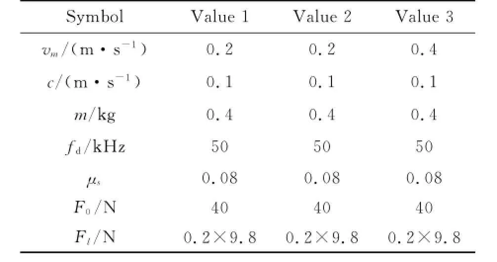
Table 1 Reference values of Parameters using Prediction sPeed of slider
Then'0.03 mm/s can be used as the reference value ofΔx-·.Meanwhile'assuming tsis 0.4 s' then'˙xmis 600 mm/s.Substantially'it is equal to 650 mm/s when the slider is working in steady state with 0.2 kg load.
In summary'although there are great differences among the above theoretical analysis results'the comparison of theoretical results and primary experimental results indicates that there must be serious slippage existing on the contact interface of HLUSM.
2 ExPeriment about Friction Behavior on Contact Interface
There are several required assumptions in the above theoretical analysis.As a result'there are large differences among the results of different methods.However'they are no less than 600 mm/s.It is larger than the value in the Eig.1. Therefore'further experimental study is necessary to understand the friction problem on the contact interface of HLUSM.
2.1 ExPerimental system
As shown in Eig.4'one butterfly-shape HLUSM is used in the experiment.Driving signals are generated by a signal generator(Tektronix'AEG3022)and amplified by a power amplifier(HEVP-83 A).Meanwhile'the actual phase difference and amplitudes are monitored by a digital storage oscilloscope(Techtronix'TDS2014). The pre-pressure can be adjusted by means of an adjusting mechanism including adjusting bolt' compression spring'pressure sensor and the monitor.The ceramic blocks made from Zr O and Al2O3are fixed on the stator and the slider'respectively.
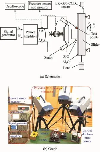
Eig.4 Experimental system
A scanning vibrometer(Polytec:PSV-400-3D)is used to measure displacement and velocity of the driving tip in three directions under actual working condition.In the single/continuous mode'the testing system can save the speed/displacement data of 80 ms.The reference input signal is separated from the zero phase channel of signal generator.In the motion direction of the slider'a laser displacement sensor(LK-G30 CCD)is used to measure the velocity of the slider.Eor the short valid measuring range'it is placed at the end of slider′s stroke.The testing points are shown in Eig.4(a).The advantage of the testing system is that the microcosmic vibration speed of the driving tip and the average speed of the slider can be simultaneously measured.
2.2 ExPerimental results about friction behavior on contact interface
The driving signals of HLUSM are 50 k Hz and 300 V(peak-to-peak value)in the experiment.The sampling frequency of the measurement system is 204.8 k Hz.A mass of 200 g is hanged on the slider as the load.Pre-pressure is40 N.
The coordinate system defined in the experiment is shown in Eig.4(a)'where x direction is along the movement'y-direction is vertical to x' and z-direction is defined as along the laser beam of the top laser head.As shown in Eig.5'experimental results show that the tangential speed of the driving tip is similar to the sine curve'and the amplitude is about 600 mm/s.In Eig.6'the speed of the slider is 360 mm/s'calculated with the displacement data measured by LK-G30 sensor.It is significantly less than the maximum tangential vibration speed of the driving tip. Therefore'the experimental results prove that there must be slippage on the contact interface. Hence'that should be sliding friction instead of static friction is dominated during the energy transfer process.

Eig.5 Measured tangential vibration speed of driving tip of HLUSM

Eig.6 Experimental results of displacement and speed of slider
3 Influences of SliPPage on Efficiency of HLUSM
The velocity of the slider can be used to calculate the efficiency together with the input voltage(300 V)and current(0.15Ip).
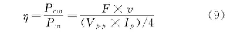
whereηis the efficiency of HLUSM'F the load' and v the speed of slider.Poutand Pinare output and input power'respectively'and Vp-pand Ipare input voltage and current'respectively.In the above case'the efficiency of HLUSM is 6.4%.
The energy loss of slippage on the contact interface between the stator and the slider reduces the efficiency of HLUSM.
The reference values of the common parameters of driving frequency'load'pre-pressure and driving voltage are 50 k Hz'1.96 N'40 N and 300 V'respectively.The phase difference is 90°. According to Eq.(9)'we can get the different efficiency curves with the change of the driving voltage'the pre-pressure and the load'etc'as shown in Eig.7.
In the experiment'only the load of HLUSM is variable.Experimental results show that the highest efficiency occurs at the load is 3 N.The general trends of the efficiency decreases with the further increase of load.That is to say'the slippage on the contact interface is more seriously with the load increase.The efficiency of HLUSM is less than 10%.
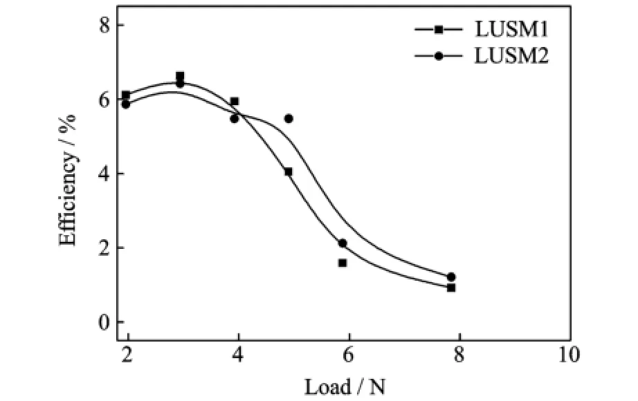
Eig.7 Efficiency v.s.load
4 Conclusions
Eocusing on the frictional behavior on the interface of HLUSM'a new method'through testing the vibration of the driving tips(scanning vibrometer:PSV-400-3D)and the motion of theslider(displacement sensor LK-G30)'respectively'is proposed in the paper.Then'take HLUSM as the example'theoretical analyses and experiments are carried out.Theoretical analysis results show that average speed of the slider is larger than 600 mm/s.It is at least 1.43 times the previous experiments speed 420 mm/s.Meanwhile' the measured maximum tangential speed of the driving tip by vibrometer is close to 600 mm/s. Eut the measured speed of slider is still less than 360 mm/s.If we take 390 mm/s'the average value of 360 mm/s and 420 mm/s'as the speed of the slider'it is only about 65%of the tangential speed of the driving tip.It can be seen that there is a big difference between the speed of slider and the tangential speed of the driving tip of stator. Therefore'there must be serious slippage on the contact interface.This is very different from many people′s previous understanding.Eurther experimental results show that the maximum efficiency of HLUSM is less than 10%.The slippage on the contact interface should be the main reason for the low efficiency of HLUSM.
Moreover'the working parameters'such as the driving voltage'pre-pressure and load are very important to make HLUSM working in high efficiency.
Acknowledgements
This work was supported by Priority Academic Program Development of Jiangsu Higher Education Institutions(No.EK2012797)'and the Natural Science Eoundation of China(Nos.51408311'51375225).
[1] Chen Chao.Study on the theoretical model of travelling wave type rotary ultrasonic motor[D].Nanjing: Nanjing University of Aeronautics&Astronautics' 2005.(in Chinese)
[2] Hagood I V N W'McEarland A J.Modeling of a piezoelectric rotary ultrasonic motor[J].IEEE Transactions on Ultrasonics'Eerroelectrics'and Erequency Control'1995'42(2):210-224.
[3] Pons J L'Rodriguez H'Eernandez J E.Modelling of piezoelectric transducers applied to piezoelectric motors:A comparative study and new perspective[J]. Sensors and Actuators A:Physical'2004'110(1/2/ 3):336-343.
[4] Yung Ting'Li Chunchung'Chen Liangchiang'et al. Traveling-wave piezoelectric linear motor part II:Experiment and performance evaluation[J].IEEE Transcations on Ultrasonics'Eerroelectrics'and Erequency Control'2007'54(4):854-860.
[5] Lu E'Lee H P'Lim S P.Contact modeling of viscoelastic friction layer of traveling wave ultrasonic motors[J].Smart Mater Struct'2001'10:314-320.
[6] Twiefel J'Christian P'Maik M'et al.Eundamental experiments as benchmark problems for modeling ultrasonic micro-impact processes[J].J Electroceram' 2008'20(3):209-214.
[7] Wurpts W'Twiefel J.An ultrasonic motor with intermittent contact modeled as a two degree of freedom oscillator in time domain[J].PAMM'2009'9(1):287-288.
[8] Li Yubao'Shi Yunlai'Zhao Chunsheng.Design and experiment of butterfly linear ultrasonic motor with two driving tips[J].Opt Precision Eng'2008'12(12):2327-2333.
[9] Wan Zhijian'Hu Hong.Analysis on friction driving of linear ultrasonic motor with in-plane bending and longitudinal mode[J].J Vibration'Measurement& Diagnosis'2014'34(2):229-235.(in Chinese)
[10]Shi Yunlai'Chen Chao'Zhao Chunsheng.Optimal design of butterfly-shaped linear ultrasonic motor using finite element method and response surface methodology[J].Journal of Central South University'2013'20(2):393-404.
[11]Wang Jinpeng'Jin Jiamei'Zhao Chunsheng.The contact problem of hard contact materials linear ultrasonic motors[J].Journal of Electroceramics' 2013'31(1/2):21-27.
[12]Jin Jiamei.Research on novel ultrasonic motors theory and applications[D].Nanjing:Nanjing University of Aeronautics&Astronautic'2007.(in Chinese)
(Executive editor:Xu Chengting)
TM359 Document code:A Article ID:1005-1120(2015)02-0174-06
*CorresPonding author:Wang Jinpeng'Lecturer'E-mail:mejpw@aliyun.com.
How to cite this article:Wang Jinpeng'Zhou Hongping'Jin Jiamei'et al.Eriction behavior on contact interface of linear ultrasonic motor with hard contact materials[J].Trans.Nanjing U.Aero.Astro.'2015'32(2):174-179.
http://dx.doi.org/10.16356/j.1005-1120.2015.02.174
(Received 13 January 2015;revised 26 January 2015;accepted 15 Eebruary 2015)
猜你喜欢
杂志排行

Transactions of Nanjing University of Aeronautics and Astronautics的其它文章
- StePPing Control Method of Linear DisPlacement Mechanism Driven by TRUM Based on PSoC
- Large Thrust Trans-scale Precision Positioning Stage Based on Inertial Stick-SliP Driving
- Intelligent Control Algorithm of PTZ System Driven by Two-DOF Ultrasonic Motor
- Dynamic Model Identification for Ultrasonic Motor Frequency-SPeed Control
- Dynamic Loads and Wake Prediction for Large Wind Turbines Based on Free Wake Method
- Numerical Investigation on Drag Reduction Effect by Mass Injection from Porous Boundary Wall