Linear Piezoelectric StePPing Motor with Broad OPerating Frequency
2015-11-24ChenXifu陈西府WangYin王寅SunMengxin孙梦馨HuangWeiqing黄卫清
Chen Xifu(陈西府)'Wang Yin(王寅)' Sun Mengxin(孙梦馨)'Huang Weiqing(黄卫清)
State Key Laboratory of Mechanics and Control of Mechanical Structures' Nanjing University of Aeronautics and Astronautics'Nanjing 210016'P.R.China
Linear Piezoelectric StePPing Motor with Broad OPerating Frequency
Chen Xifu(陈西府)'Wang Yin(王寅)' Sun Mengxin(孙梦馨)'Huang Weiqing(黄卫清)*
State Key Laboratory of Mechanics and Control of Mechanical Structures' Nanjing University of Aeronautics and Astronautics'Nanjing 210016'P.R.China
The existing resonant linear piezoelectric motors must operate with high working voltage in resonant condition'resulting in their narrow operating frequency range and poor running stability.Here'with the large displacement output characteristics of piezoelectric stacks'the trajectory at the drive foot of stator is firstly produced with two space quadrature piezoelectric actuators excited by sawtooth wave and square wave.Secondly'the friction drive principle of motor is used to analyze the working mechanisms of the continuous stepping motion.Einally'the motor prototype is designed and experiments are carried out.The experimental result shows that the motor can stably operate within the scope of 350 Hz to 750 Hz.When the excitation voltage is 30 V and pre-load is 3 N or 10 N'the lateral amplitude of the drive foot is approximately 4μm and the stable average interval ranges from 3.1μm to 3.2μm with the error rate of 5%—7.5%.
linear motor;piezoelectric stack;stepping motor;broad operating frequency
0 Introduction
Linear piezoelectric motors have wide application prospect in precision positioning'instrumentation'biomedical and many other fields[1-3]. Eor resonance linear piezoelectric motors have the advantages of compact structure'fast response' low noise and no electromagnetic interference' many outstanding researches have been conducted[4-5].Resonance linear piezoelectric motors are greatly affected by the temperature and the structure design due to resonance condition[6].Therefore'there is a boom in the development of nonresonant piezoelectric motors[7].
In recent decades'using the perfect characteristics of the piezoelectric stack under non-resonant conditions'piezoelectric stepping motors with high positioning accuracy are developed[8-9]' among which the inchworm principle and inertial impact non-resonant type linear motors are welldeveloped[10].However'the operation frequency of above two motors is low.At the same time' high requirements are put forward in drive signal and structure accuracy.In recent years'Huang et al.[11]proposed non-resonant friction drive motors based on elliptical orbit.The investigation of friction drive mechanism shows that it is necessary for the stator and the mover to separate effectively in the second half of the elliptical motion cycle[12].Thus the motor can stably operate only under high frequency and the piezoelectric ceramics driver need larger power.In addition'effective separation of motor also put forward high demand on contact condition between stator and mover'so preloading device should be properly designed and the assembly accuracy should be guaranteed.
The sawtooth wave and square wave signals will be used to produce two vertical linear motion trajectories at drive foot so as to realize the friction drive between the stator and the mover.Dueto the step characteristics of square wave signals' it is easy to implement vertical separation between the stator and mover so that the motor can run in a wider and lower frequency domain.
1 Working Mechanism of Motor
1.1 OPerational cycle of motor
A piezoelectric actuators based on two groups orthogonal structure(see Eig.1)includes lateral actuator(parallel to the motion direction of the mover)and vertical actuator(perpendicular to the motion direction of the mover).Two groups of actuators are permanent connected to the drive foot of stator.Lateral actuators provide drive foot of stator reciprocating displacement in motion direction'and the elongation and shortening of another actuator can realize the contact and separation for drive foot and mover.Thus the separation between the stator and the mover will just be controlled by the vertical actuator.
In Eig.1'in the initial state'vertical and lateral actuators are dormant'so the contact force between the stator and the mover is the initial pre-pressure.When we apply cycle square wave voltage to the vertical actuator'the duty ratio of the square wave voltage should be greater than 0.5.It is 0.75 in the paper.
In duration 1'excitation voltages are applied to both actuators at the same time.Vertical actuator is excited by the square wave voltage.At the beginning'vertical actuator elongates rapidly and the contact force of the stator and the mover is the most stressful.Lateral actuator is excited by the triangle wave voltage.At the time'triangle wave is at up slope stage'the lateral actuator continues to elongate.Therefore'the mover will be driven rightward by the friction of contact interface between the stator and the mover.
In duration 2'the vertical actuator is excited by square wave voltage which is zero and the vertical actuator shrink to the initial state rapidly. At this moment'the pressure between the stator and the mover is the minimum.At the same time'we apply lateral actuators to the triangle wave voltage.Triangle wave is located in the down slope stage'so the lateral actuator continues to contract.At the time'the mover will return under the effect of friction force due to the initial pressure between the stator and the mover.

Eig.1 Operation principle of motor
However'because the duty ratio of square wave voltage is greater than 0.5 and the friction between the stator and the move in duration 2 is less than the friction force in duration 1'the movement distance in duration 2 is smaller than that of duration 1.It can realize the dynamic motion to the right within the whole motion cycle. At the same time'the drive foot will restore the initial state.
Erom the above analysis'the vertical actuator and the lateral actuator are excited by the excitation signal as shown in Eig.1(b).At the beginning of duration 1'the drive foot keeps compressing with the elongation of vertical actuator. In duration 1'the drive foot move to the rightwith the rising of voltage signal.At the end of duration 1'vertical actuator shrinks rapidly. Therefore'the drive foot shrinks with the vertical actuator.Entering into duration 2'lateral actuators also shrinks rapidly and the drive foot moves along with the shrinkage of the lateral actuator. At the end of duration 2'the drive foot returns to the initial position.Therefore'the trajectory of the drive foot is a rectangular path in the whole cycle.
1.2 Driving PrinciPle of motor
According to mechanics'when excited by the DC voltage'the output characteristics of piezoelectric stack can be described as follows
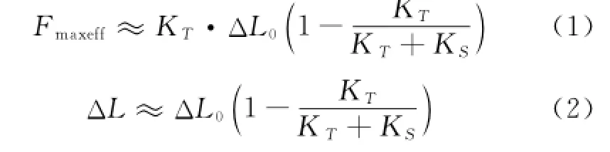
where FmaxeffandΔL are the maximum effective output force and the maximum effective output displacement'respectively'KTand KSthe stiffness of load mechanism and the stiffness of the piezoelectric stack'respectively.ΔL0is no-load displacement.
Eased on piezoelectricity'when piezoelectric stack with number of layers n and piezoelectric constant d33are excited by DC voltage U0'ΔL0is approximately described as

Therefore

In duration 1 The maximum output displacementδlon1and the maximum output force Flon1are

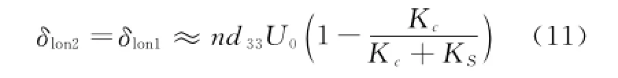
where Kcand Fcare the contact stiffness and contact force between the stator and the mover.F0is the initial pre-load of the motor.
The output displacement of drive footδtra1is

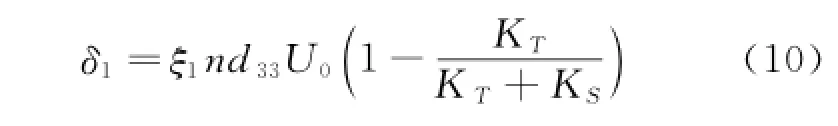
Eorward distance of moverδ1is
In duration 2 Shrinking displacement of drive footδlon2is
The output force of vertical actuator Flon2and contact force between the stator and the mover Fcis

The shrinking displacement of lateral actuator and drive footδtra2is


Therefore'in the whole cycle'forward distance of moverδTis

The backward distance of moverδ2is
Therefore'selecting proper excitation frequency f'vertical actuator excitation voltage vlon'lateral actuator excitation voltage vtraand preload of motor F0can guarantee the stability of factorsξ1and ξ2during the motor movement process'which can make the motor realize precise stepping motions.
2 Structure of Motor
The motor is composed of two piezoelectric actuators(lateral actuator and vertical actuator)' mover(linear guide)'flexible support'preload guide rail and preloading pin.One end of the stator group is fixed with preload guide rail'and theother end is fixed to base.With restoring force produced by flexible support'the stator stay in touch with the mover to make the piezoelectric linear motor self-lock on the power-off.The structure of the motor is shown in Eig.2.
The vertical and lateral actuators have the same structure'including the support block(a1' a2)'the tension spring(a3'a4)'pin(a5'a6)' circlip(a7'a8)'the laminated piezoelectric ceramic(a9)'fixed wedge(aa)'adjusting wedge(ab)and adjusting block(ac).Support blocks connect into an organic whole through the tension spring and pin.Laminated piezoelectric ceramic group(a9)and fixed wedge(aa)'adjusting wedge(ab)and adjusting block(ac)concatenate axially between support blocks(a1'a2).
3 ExPeriment
The prototype is designed and fabricated according to Eig.3.Keyence XL-80 laser displacement sensor(LDS)is adopted to measure displacement of the mover and the amplitude of the actuator.The experiment set-up of motor is shown in Eig.4.
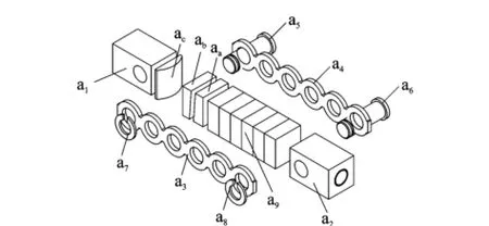
Eig.3 Diagram of piezoelectric actuator unit

Eig.4 Experiment device of motor
3.1 Lateral amPlitude characteristics of drive foot
In Eig.5'the lateral amplitude of the drive foot of stator is excited by 450 Hz sinusoids. When the preload is 3 N or 10 N'the lateral amplitude is stable in a long time and the value is about 4μm.
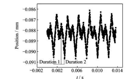
Eig.5 Lateral displacement curve of drive foot
3.2 SteP characteristics of motor
Eig.6 shows large stroke displacement curves of motor when frequency is 450 Hz.It can be seen that the motor remains good characteristics of speed stability in wide frequency range.In Eig.6'the stepping motor has high accuracy and stability under the same pressure.

Eig.6 Displacement curves of motor
Eig.7 shows the average pace curves of motor under different frequency.Under the condition that the preload is 3 N and frequency ranges from 350 Hz to 600 Hz'the steplength ranges from 3.08μm to 3.33μm'the average pace is 3.20μm and the average error is within 4%. When preload is 10 N and frequency ranges from 450 Hz to 750 Hz'the steplength ranges from 2.85μm to 3.31μm'the average interval is 3.08 μm and the error is within 7.5%.Erom the above results'it can be concluded that slip rate of relative movement between the stator and the mover is the same'when the motor operates stably in a certain frequency range with preload 3 N or 10 N.

Eig.7 Average pace curves of motor
The stepping characteristics experiments indicate that the motor has uniform step in 350—750 Hz frequency range.Compared with the resonance type piezoelectric motors whose speed features are greatly affected by temperature'frequency and so on'the motor presented in the paper can ensure good stability in a wide domain. The stability for the motor in broad domain lies in two factors.One is that the output displacement of piezoelectric stacks remains unchanged in broadband domain'so the frequency change have little effects on the horizontal amplitude and vertical amplitude of the drive foot.The other is that the friction drive can produce stable displacement difference in wide frequency domain between extending stroke and return stroke.
3.3 Velocity characteristics of motor
Eig.8 shows the velocity curves in frequency domain when the motor operates stably.It can be seen from the diagram that when preload is 3 N' the stable operation frequency of the motor is 350—600 Hz.When preload is 10 N'the stable operation frequency of the motor is 450—750 Hz. In addition'the relationship between speed and frequency is approximately linear'which suggests that under the same preload'the motor can keep the same step within wide frequency domain.
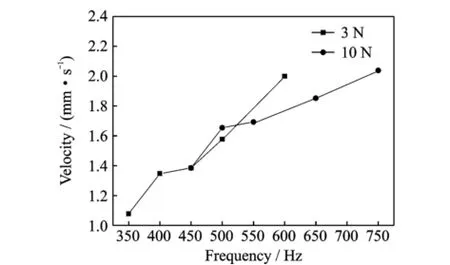
Eig.8 Velocity curves of motor
4 Conclusions
The theoretical study and experimental results show that the friction drive and non-resonant piezoelectric linear motor can achieve stable operation in a low and wide frequency range.We can obtain the following conclusions.
(1)The lateral amplitude of the stator drive foot is stable in a wide frequency range'which provides a precondition for high positioning accuracy.
(2)The displacement experiments indicate that motor presents good linearity in a large stroke'which implies that the motor possesses good speed stability.
(3)The motor has good stepping character. The experimental results show that the average step of the motor ranges from 3.1μm to 3.2μm in the frequency range of 350—750 Hz.
(4)When preload is 3 N and excitation voltage is 30 V'the stable operation speed of the motor is maximum 2 mm/s and the maximum thrust is 1.6 N.
Acknowledgements
This work was supported by the National Natural Science Eoundation of China(Nos.51375224'51405420)'and the Natural Science Eoundation of Jiangsu Province(No.EK20140474).
[1] Wang Yin'Huang Weiqing.Linear ultrasonic motor using longitudinal vibration[J].Transactions of Nanjing University of Aeronautics&Astronautics' 2012'29(1):40-45.
[2] Suzuki M'Hosaka H'Morita T.Resonant-type smooth impact drive mechanism actuator with two langevin transducers[J].Advanced Robotics'2012' 26(3/4):277-290.
[3] Mandar Deshpande'Laxman Saggere.An analytical model and working equations for static deflections of a circular multi-layered diaphragm-type piezoelectric actuator[J].Sensors and Actuators'A:Physical' 2007'136(2):673-689.
[4] Zhang Jiantao'Huang Weiqing'Zhu Hua'et al. Lead screw linear ultrasonic motor using bending vibration modes[J].Transactions of Nanjing University of Aeronautics and Astronautics'2009'26(2):89-94.
[5] Sun Zhijun'Shuai Shuanghui'Huang Weiqing.Control of robot driven by multiple ultrasonic motors based on robust parameter design[J].Transactions of Nanjing University of Aeronautics and Astronautics' 2009'26(4):243-250.
[6] Shi Yunlai'Li Yubao'Zhao Chunsheng.Optimum design of a linear ultrasonic motor based on in-plane modes[J].Proceedings of CSEE'2008'30(28):56-60.(in Chinese)
[7] Wen Jianming.Study on planar inertia piezoelectric moving mechanism[D].Jilin'China:Jilin University'2009:6-13.(in Chinese)
[8] Duan Z'Wang Q.Development of a novel high precision piezoelectric linear stepper actuator[J].Sensors and Actuators A:Physical'2005'118(2):285-291.
[9] Hii K E'Vallance R R'Pinar MengüçM.Design' operation'and motion characteristics of a precise piezoelectric linear motor[J].Precision Engineering' 2010'34(2):231-241.
[10]Li J'Sedaghati R'Dargahi J'et al.Design and development of a new piezoelectric linear inchworm actuator[J].Mechatronics'2005'15(6):651-681.
[11]Huang Weiqing'Meng Yimi.Design of a new type of piezoelectric linear motor based on non-resonant vibration[J].Chinese Mechanics Engineering'2009'20(14):1717-1721.(in Chinese)
[12]Chen Xifu'Xu Jingjing'Wang Yin'et al.Working mechanism of friction-drive-type linear motor with piezoelectric stacks[J].Journal of Vibration'Measurement&Diagnosis'2011'31(6):742-746.(in Chinese)
(Executive editor:Xu Chengting)
TM356 Document code:A Article ID:1005-1120(2015)02-0137-06
*CorresPonding author:Huang Weiqing'Professor'E-mail:mehwq@nuaa.edu.cn.
How to cite this article:Chen Xifu'Wang Yin'Sun Mengxin'et al.Linear piezoelectric stepping motor with broad operating frequency[J].Trans.Nanjing U.Aero.Astro.'2015'32(2):137-142.
http://dx.doi.org/10.16356/j.1005-1120.2015.02.137
(Received 19 Eebruary 2014;revised 6 March 2014;accepted 25 March 2014)
杂志排行

Transactions of Nanjing University of Aeronautics and Astronautics的其它文章
- StePPing Control Method of Linear DisPlacement Mechanism Driven by TRUM Based on PSoC
- Large Thrust Trans-scale Precision Positioning Stage Based on Inertial Stick-SliP Driving
- Intelligent Control Algorithm of PTZ System Driven by Two-DOF Ultrasonic Motor
- Dynamic Model Identification for Ultrasonic Motor Frequency-SPeed Control
- Dynamic Loads and Wake Prediction for Large Wind Turbines Based on Free Wake Method
- Numerical Investigation on Drag Reduction Effect by Mass Injection from Porous Boundary Wall