Polyacrylonitrile/Graphene-Based Coaxial Fiber-Shaped Supercapacitors
2021-04-08RUANYingpeng阮英鹏DUZheSUNXiaoxia孙晓霞ZHANGKunYAOYeWANGXinhou王新厚
RUAN Yingpeng(阮英鹏), DU Zhe(杜 哲), SUN Xiaoxia(孙晓霞)*, ZHANG Kun(张 坤), YAO Ye(姚 晔), WANG Xinhou(王新厚)
1 Key Laboratory of Textile Science & Technology, Ministry of Education, Donghua University, Shanghai 201620, China
2 College of Textiles, Donghua University, Shanghai 201620, China
3 Institute of Refrigeration & Cryogenics, Shanghai Jiao Tong University, Shanghai 200240, China
Abstract: Supercapacitors have huge potential applications in the field of wearable electronic devices, such as flexible displays, flexible biosensors and implantable multimedia devices, due to their high-power density, fast charge-discharge rates, long cycling life, and relatively simple configuration. In this paper, we demonstrated hierarchically porous and continuous reduced graphene oxide-polyacrylonitrile@polyacrylonitrile (rGO-PAN@PAN) coaxial fibers with certain strength, excellent electrochemical performance through coaxial wet spinning and thermal reduction. Coaxial fibers are carbonized at high temperature and have a graded porous structure with a conductivity of 1 703 S/m. The areal specific capacitance of the supercapacitor assembled by polyvinyl alcohol/sulfuric acid (PVA/H2SO4) gel electrolyte is 11.56 mF/cm2, and its energy density reaches 0.21 mW·h/cm3, showing good electrochemical performance. Graphene-based coaxial fibers prepared by wet spinning have a great prospect of application in electronic devices due to their excellent properties.
Key words: coaxial fiber; wet spinning; polyacrylonitrile(PAN); graphene; fiber supercapacitor
Introduction
With the continuous development of the application of smart wearable products, the combination of electronic components and textiles can endow clothing with such functions as signal transmission, intelligent induction, energy storage and information processing. Supercapacitors are featured by fast charge-discharge capacity[1], longer cycling life[2], low-cost[3], excellent reversibility[4], high-power density[5-6], and so on. They have been widely applied in the fields of digital cameras, mobile phones, electrical tools and pulse laser techniques[7-8]. Because of their stable structures and excellent performances, fiber supercapacitors have attracted more attention and research[9-10].
Kouetal.[11]proposed a coaxial wet spinning assembly approach to continuously spin polyelectrolyte-wrapped graphene/carbon nanotube coaxial fibers that were used directly as safe electrodes to assemble two-ply yarn supercapacitors. Yangetal.[12]developed a novel family of highly stretchable, fiber-shaped high-performance supercapacitors. Aligned carbon nanotube (CNT) sheets were sequentially wrapped on an elastic fiber and served as two electrodes. Zhaoetal.[13]prepared a series of high-performance, all-solid, lightweight and flexible asymmetric supercapacitors (ASCs) using cabbage-like ZnCo2O4as the positive electrode material, porous nanowires as the negative electrode material, and flexible carbon nanotube films (CNTFs) as the collector. Baeetal.[14]presented a prototype of a high-efficiency fiber-based electrochemical microsupercapacitor using ZnO nano-wires (NWs) as electrodes. Leetal.[15]used carbon microfibers to design a highly flexible coaxial fiber-optic supercapacitor with high energy density and power density that could eventually be woven into self-powered wearable electronics. However, due to the differences in raw materials, preparation technology and post-treatment methods, physical and mechanical properties of graphene fibers are difficult to meet the wearable requirements. Moreover, the introduction of conductive polymers and CNTs also increases the cost of spinning.
In order to improve the strength of graphene fibers and reduce the cost to a certain extent, a rapid and efficient preparation method of forming coaxial fibers supercapacitor was developed in this paper. The coaxial porous fibers were prepared by wet spinning and thermal reduction, and then the properties of the fiber supercapacitors were studied by assembling them with gel electrolyte.
1 Experiments
1.1 Materials
Graphene oxide (GO) was purchased from Nanjing XFNANO Materials Tech Co., Ltd., China. Anhydrous ethanol was purchased from Shanghai Lingfeng Chemical Reagent Co., Ltd., China. Polyacrylonitrile(PAN) was purchased from Shanghai Macklin Biochemical Technology Co., Ltd., China. Dimethyl sulfoxide (DMSO) and phenol formaldehyde (PF) resin were purchased from Shanghai Titan Scientific Co., Ltd., China. Calcium chloride (CaCl2) was purchased from Sinopharm Chemical Reagent Co., Ltd., China. Sulfuric acid (H2SO4, 98% in weight percent) was purchased from Kunshan Jingke Microelectronics Material Co., Ltd., China. Deionized (DI) water was from Donghua University. The materials were used as received without further purification.
1.2 Preparation of PAN/GO solution
Certain PAN powder was dissolved in DMSO to produce a PAN solution with a concentration of 140 mg/mL. The GO powder was dispersed in a certain amount of the DMSO solution. The ultrasonic processing technology (100 W, 30 min, 20 ℃) was used to make GO evenly dispersed before use. The prepared GO solution was mixed into the PAN solution, and the GO concentration was set to 25% in weight percent with respect to the PAN solution. The mixture was homogenized at 10 000 r/min for 20 min.
1.3 Preparation of reduced GO-PAN (rGO-PAN) @PAN coaxial fibers
Coaxial fibers were prepared by wet spinning. The specific preparation process was shown as follows. The pure PAN solution and the PAN/GO mixed solution were injected into the syringe respectively, and then extruded by the syringe pump at a speed of 10 mL/h into the solidification bath through a needle with an inner diameter of 330 μm and an outer diameter of 1.12 mm. The coagulation bath was the CaCl2ethanol solution with a weight percent of 5%, in which the volume ratio of ethanol to water was 1∶3. The colloidal fiber extruded by the spinneret was placed in the coagulation bath for 30 min, then removed from the coagulation bath, washed with water and ethanol, and finally wound onto the poly tetra fluoroethylene(PTFE) tube (shown in Fig. 1). The prepared GO-PAN@PAN fibers were tensioned at the room temperature for 12 h, followed by vacuum drying at 60 ℃ for 12 h.
The obtained GO fibers were reduced by the thermal annealing method at the temperature of 800 ℃. GO fibers were heated from the room temperature to 300 ℃ at a rate of 10℃/min and maintained at this temperature for 30 min to reduce the GO fibers partly. The rGO fibers were heated up to 800 ℃ at a rate of 4 ℃/min and maintained at this temperature for 3 h. It should be noted that the thermal annealing process was under the protection of high-purity nitrogen (shown in Fig. 1). The rGO fibers were washed by DI water and dried at the room temperature. The product is denoted as 25%-rGO-PAN@PAN. For comparison, pure PAN fibers and 25%-rGO-PAN fibers were also prepared.
1.4 Assembly of porous graphene composite FSSCs
The polyvinyl alcohol/sulfuric acid (PVA/H2SO4) gel electrolyte was prepared with the following method. Briefly, 1 g PVA powder was added to 10 mL DI water. Subsequently, the mixture was heated to 90 ℃ under vigorous stirring for 30 min until the solution was clarified. After being cooled down to the room temperature, 1 g H2SO4solution was added and stirred thoroughly. To fabricate all-solid-state FSSCs, two fiber electrodes were immersed in PVA/H2SO4gel electrolyte and then placed parallel to each other on a polyethylene terephthalate (PET) substrate (shown in Fig. 1).
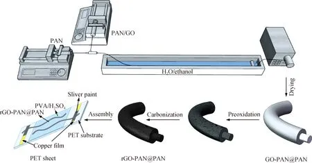
Fig. 1 Roadmap for producing rGO-PAN@PAN electrodes and assembled fiber-shaped supercapacitiors (FSSCs)
2 Characterization
The surface morphology of fibers was characterized by a scanning electron microscope (SEM, HITACHI, TM3000, Japan). Fourier transform infrared (FTIR) spectra were tested by a Nicolet NEXUS-670 to characterize the chemical structure of fibers. In order to test the pore volume, the sample was first degassed at 300 ℃ under high vacuum for 10 h, and then the isotherm of nitrogen adsorption and desorption was obtained by a Micromeritics ASAP 2020 static volumetric gas adsorption instrument under 77 K. The specific surface area was calculated by Brunauer-Emmett-Teller (BET) technique. The linear density of the fiber was measured by using a Sartorius BT125D electronic balance. The tensile properties were measured by using a single fiber tension tester (XQ-2, Shanghai New Fiber Instrument Co., Ltd., China).
Cyclic voltammetry (CV) and galvanostatic charge-discharge (GCD) were measured with an electrochemical workstation (CHI600E, Shanghai Chenhua Instrument Co., Ltd., China) in a two-electrode configuration. The specific capacitance, the energy density and the power density were calculated as reported in Ref.[16]. The capacitance of the supercapacitorsCcellin a two-electrode cell was calculated from the GCD curves at different current densities:
Ccell=i/(dV/dt),
(1)
whereiandVare the current and the operating voltage, respectively.Ccellcan also be calculated by the CV method:
(2)
whereQ,V1,V2,vandi(V) are the total charge, the low potential, the high potential, the scanning rate and the current, respectively. The areal specific capacitanceCAand the volumetric specific capacitanceCVof single fiber electrodes were calculated according to
CA=2Ccell/Asingle,
(3)
CV=2Ccell/Vsingle,
(4)
whereAsingleandVsingleare the surface area and the volume of a single fiber. The length of the fiber electrode is the active part, which is measured with a ruler. The diameter of the fiber electrode was measured with an SEM to determine the fiber electrode area. The entire device areal energy densityEcell, Aand volumetric energy densityEcell, Vcan be calculated according to
Ecell, A=CAV2/(8×3 600),
(5)
Ecell, V=CVV2/(8×3 600).
(6)
The areal energy densityEAand the volumetric energy densityEVof a single electrode can be calculated according to
EA=4Ecell, A,
(7)
EV=4Ecell, V.
(8)
3 Results and Discussion
3.1 Morphology characterization of fibers
As can be seen from Fig. 2, the diameter of the carbonized fiber is between 80 μm and 120 μm. Figure 2(a) shows that on the surface of the pure PAN fiber, the fiber shape is straighter and has uniform folds, which is caused by the tension in the wet spinning process. Figure 2(b) shows some small particles on the surface of the fiber, but no obvious holes appear and the surface is relatively dense. Figures 2(d) and (e) show that when GO is added to the fiber, obvious depressions and partial holes appear on the fiber surface, and folds and particles increase, which can significantly increase the specific surface area of the fiber. PAN solution provides a good substrate for dispersion of GO. The interaction between GO and PAN macromolecules can effectively reduce GO reunion and achieve uniform dispersion[17-18]. Figures 2(g) and (h) show that due to the existence of the sheath-core structure of coaxial fibers, the fibers are difficult to spin and draw with the addition of GO, resulting in larger fiber diameters. Since no GO agglomeration is observed, the SEM image also demonstrates good dispersion of GO. In addition, the heterogeneous layered porous structure of the surface increases the specific surface area of the fiber, which promotes the interaction between the fiber electrodes and electrolyte ions and improves the electrochemical performance. As shown in Figs. 2(c), (f) and (i), a small number of voids and particles exist in the cross-section of the pure PAN fiber. For rGO-PAN blended fibers, the fiber aperture becomes larger. The coaxial fibers show obvious pore distribution with mesoporous and macroporous structures.
3.2 FTIR spectra of fibers

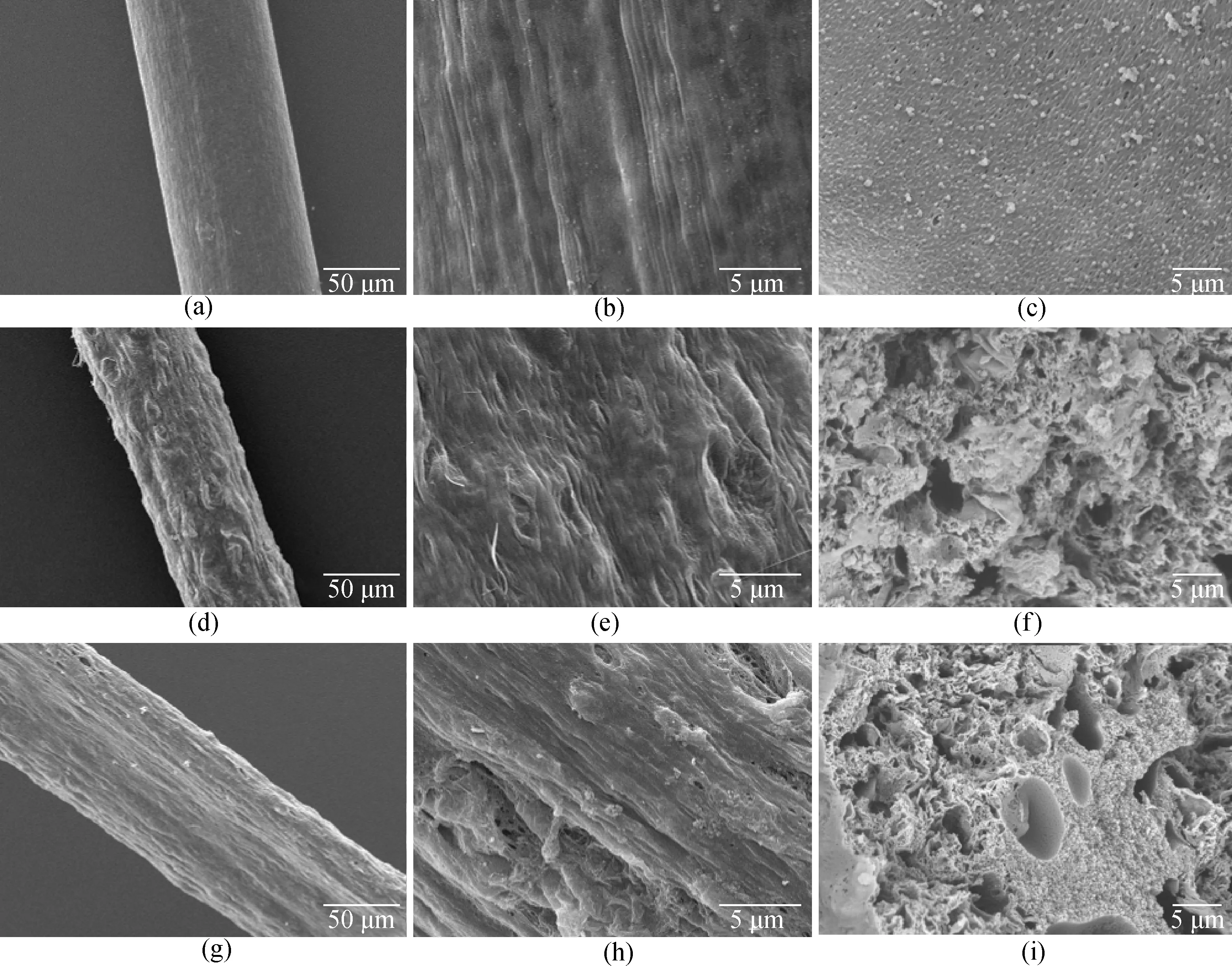
Fig. 2 SEM images of fiber surface and cross-section with different magnification ratios: (a)-(c) PAN fibers; (d)-(f) 25%-rGO-PAN fibers; (g)-(i) 25%-rGO-PAN@PAN coaxial fibers
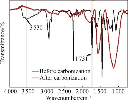
Fig. 3 FTIR spectra of 25%-rGO-PAN fibers before and after carbonization
3.3 Tensile properties of fibers
The load of fiber supercapacitors affects the practicability of electronic devices. As shown in Fig. 4, the load of the fibers decreased significantly when rGO was added to the PAN fiber. For coaxial fibers, PAN at the core layer can provide better load. The load of 25%-rGO-PAN@PAN coaxial fibers is increased by 232% compared with that of 25%-rGO-PAN fibers, which greatly improves the utility of fiber supercapacitors.
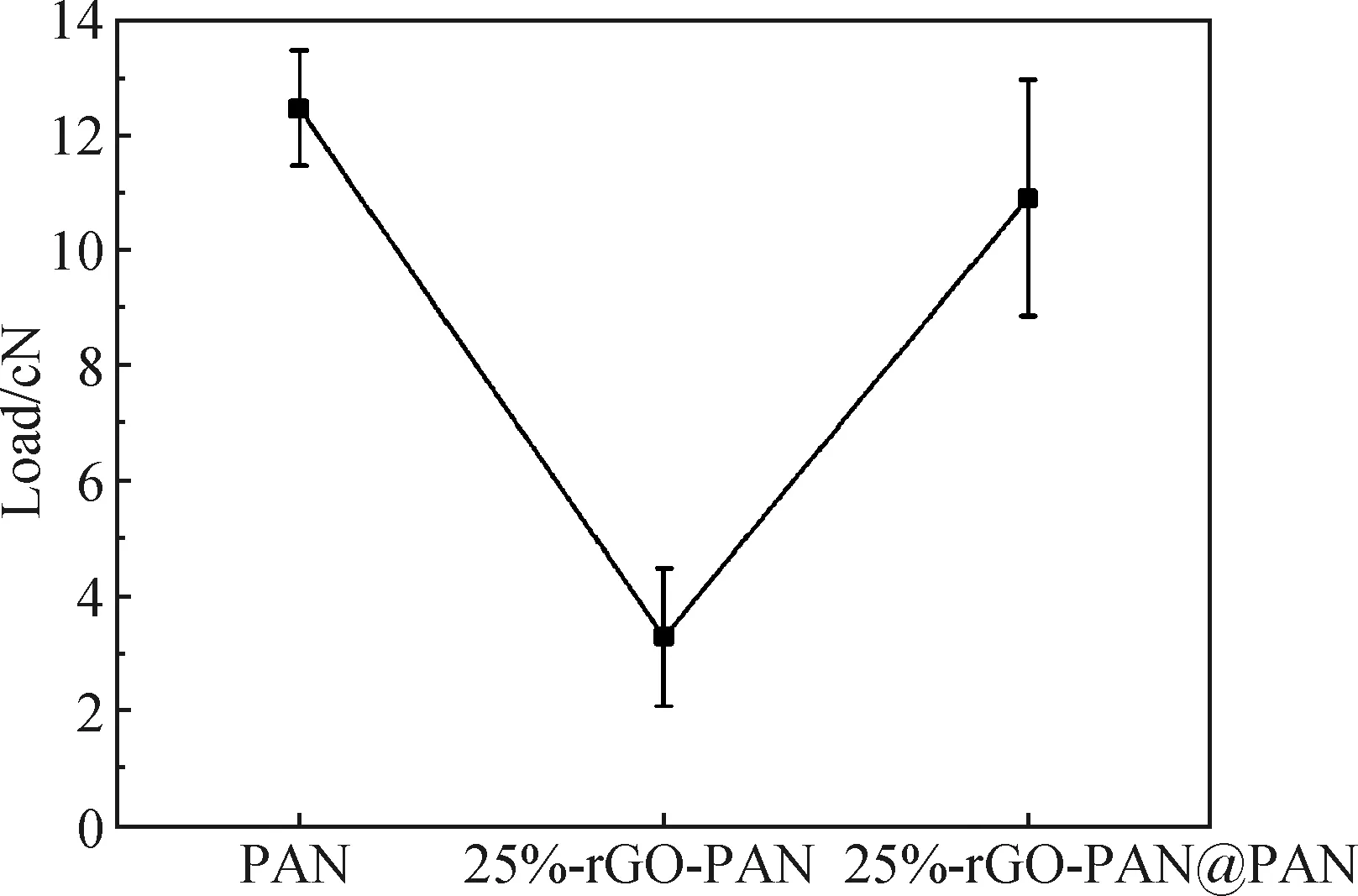
Fig. 4 Tensile properties of fibers
3.4 BET analysis of coaxial fibers
The BET test can effectively analyze the specific surface area and the pore size range of the porous material through nitrogen isothermal adsorption-desorption curve.
The BET equation is
(9)
wherePis the partial pressure of nitrogen,P0is the saturated vapor pressure of nitrogen at liquid nitrogen temperature,V0is the actual adsorption volume of nitrogen on the sample surface,Vmis nitrogen monolayer saturation adsorption volume, andCis the constant related to the adsorption capacity of the sample.
In order to study the internal pore distribution of the coaxial fiber, the Barret-Joyner-Halenda (BJH) method was used to calculate the pore diameter distribution of the fiber. An obvious mesoporous peak appeared at 9.578 nm for the 25%-rGO-PAN@PAN coaxial fibers, and the pore diameter was mainly distributed at 3-130 nm, indicating the existence of mesopore and macropore in the fiber. The result is consistent with the SEM results. It can be seen from Figs. 5 and 6 that the coaxial fiber has a large specific surface area and a mesoporous structure, which can provide more transmission channels and effective specific surface area for electrolyte ions, thus improving charging-discharging speed and the specific capacitance of the fiber capacitor.
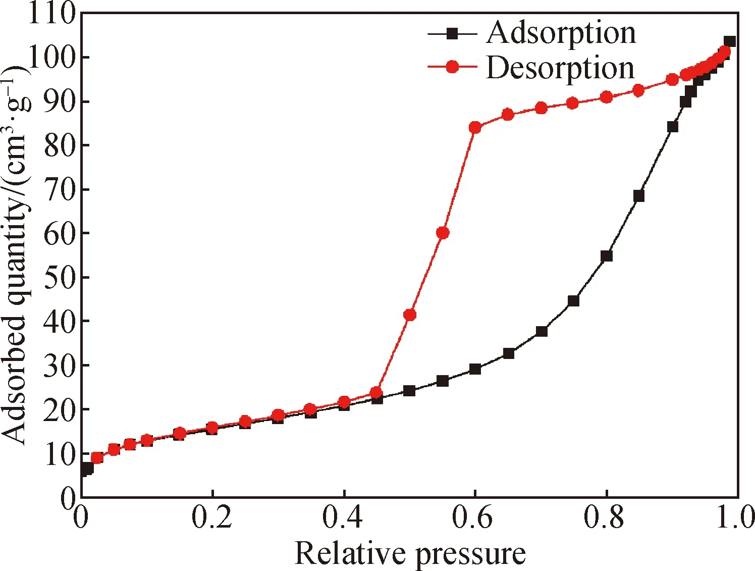
Fig. 5 Nitrogen isothermal adsorption-desorption curves of 25%-rGO-PAN@PAN coaxial fibers
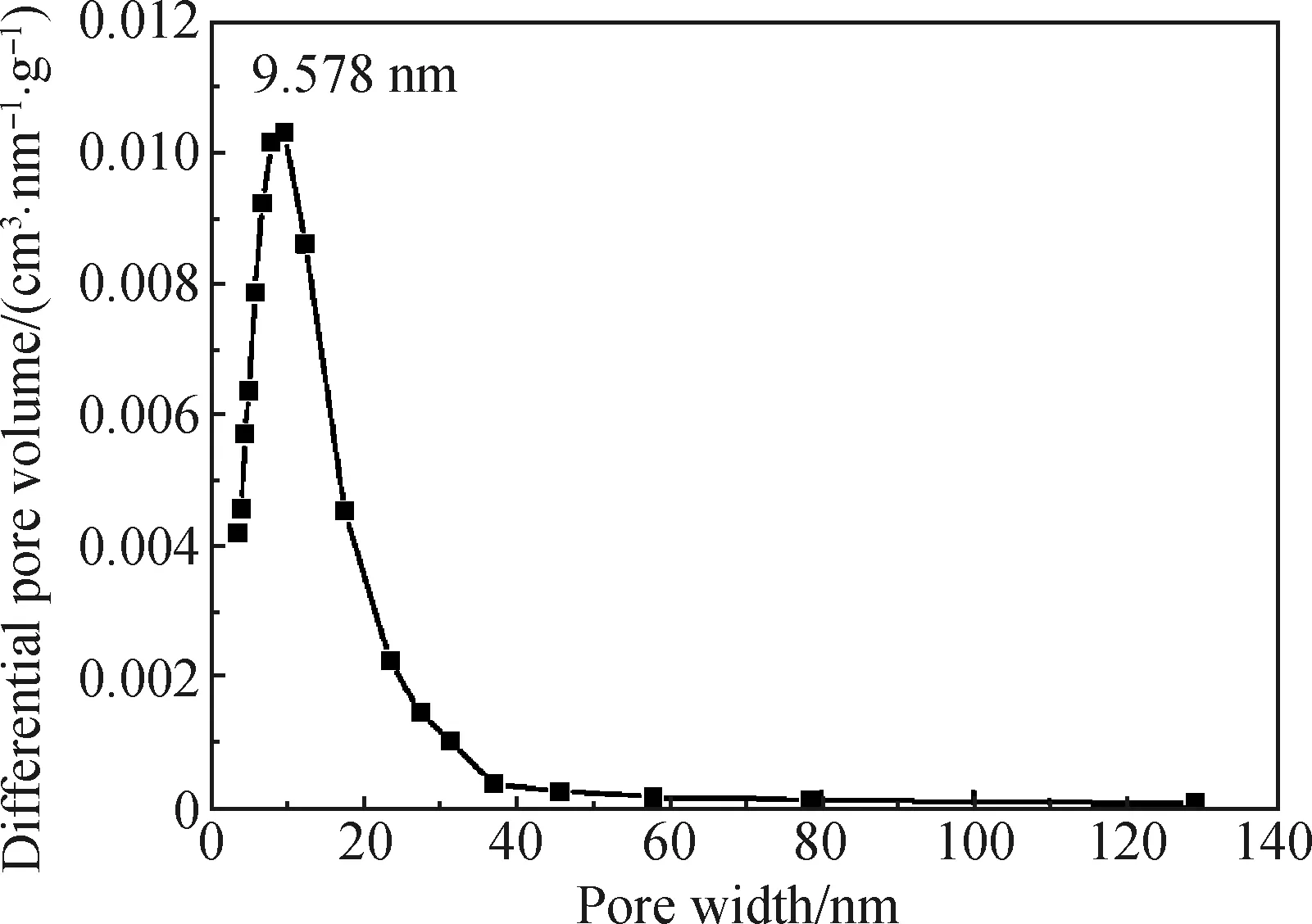
Fig. 6 Pore distribution of 25%-rGO-PAN@PAN coaxial fibers
3.5 Electrochemical properties of fiber electrodes
To investigate the electrochemical properties of the porous coaxial graphene-based fiber electrodes, CV and GCD tests were carried out in a two-electrode cell by using 1 mol/L PVA/H2SO4gel electrolyte (shown in Fig. 1).CAandEAof these graphene-based fibers were calculated from the CV results and their electrochemical performance was analyzed with the aid of the BET specific surface area, pore size distribution (PSD), and electrical conductivity[19-20].
The electrical conductivity fits the equation:
(10)
whereGis the conductance,kis the electrical conductivity,Ais the cross-sectional area, andLis the clamping length.
The conductivity of fibers is shown in Fig. 7. It can be seen from the electrical conductivity results that with the addition of graphene, the electrical conductivity of 25%-rGO-PAN fibers (2 201 S/m) is about three times higher than that of pure PAN fiber (526 S/m). However, the electrical conductivity (1 703 S/m) of the 25%-rGO-PAN@PAN coaxial fibers decreases compared with that of the 25%-rGO-PAN fiber, which is due to the increase of pure PAN components in the coaxial fibers. As a result, the fiber diameter with high conductivity per unit length increases, which reduces the conductivity of fibers, but is still higher than that of the pure PAN fiber.
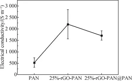
Fig. 7 Electrical conductivity of fibers
Figure 8 shows the CV curves of FSSCs composed of 25%-rGO-PAN@PAN coaxial fibers in the scanning rate range of 5-200 mV/s, and the measured scanning rate range is 0-0.8 V. The CV curves of cyclic volt-ampere curves at different scanning speeds are all approximately rectangular, indicating that the fiber supercapacitor has typical double-layer capacitance behavior and fast current response. Figure 9 shows the GCD curves of FSSCs composed of 25%-rGO-PAN@PAN coaxial fibers at various current densities. It is obvious that all curves show a triangular shape. In addition, the charge curves are symmetric to their corresponding discharge counterparts, demonstrating the high reversibility of FSSCs and the rapid charge transport between fiber electrodes.
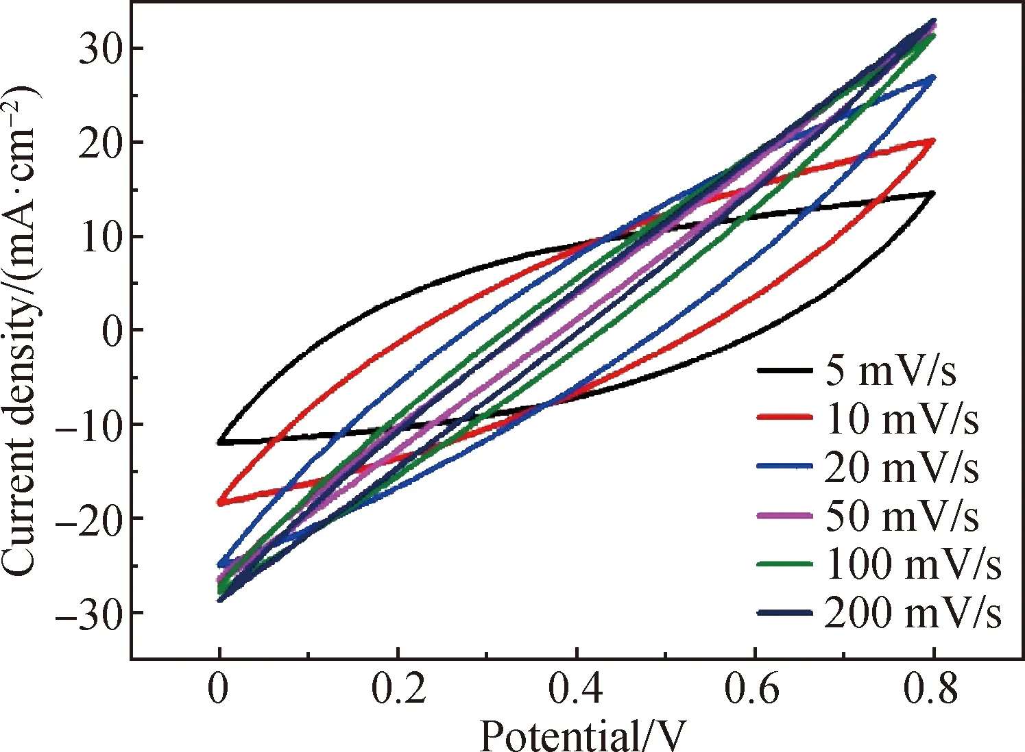
Fig. 8 CV curves of FSSCs
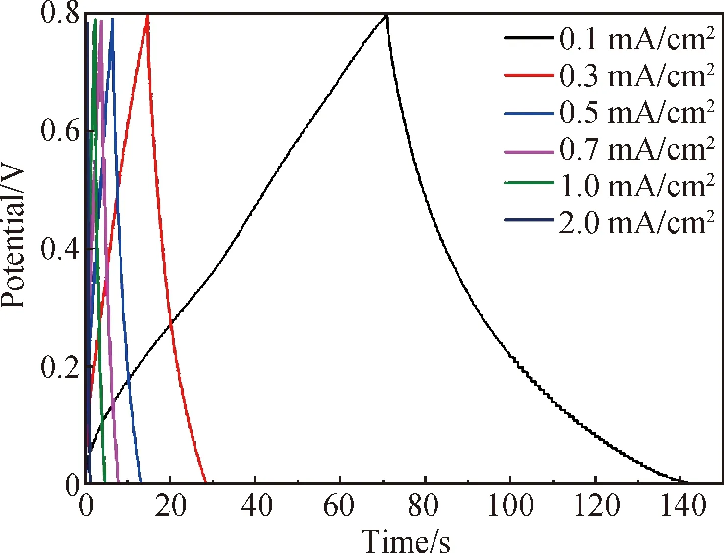
Fig. 9 GCD curves of FSSCs
At different scanning speeds, the CV curves are different. It can be seen from Fig. 8 thatCAof the FSSCs is 11.56 mF/cm2(CVis 2.313 F/m3) at the scanning rate of 5 mV/s.EAandEVof a single electrode reach 1.03 μW·h/cm2and 0.21 mW·h/cm3, respectively, exceeding these of some commercial capacitors. The core layer in the coaxial fibers is composed of pure PAN, which can provide better charge storage capacity, while the mixture of rGO and PAN has large specific surface area and small pore size, which can provide excellent charge conduction performance. The electrochemical performance of the fiber supercapacitor can be improved significantly by such a classification design.
4 Conclusions
A coaxial wet spinning assembly strategy is proposed to prepare graphene-based coaxial fibers. This method can effectively disperse the graphene uniformly in the fiber, and continuous spinning can be carried out by this method. After thermal reduction, the fiber can still maintain the sheath-core structure, and is endowed with a hierarchical porous structure, so as to improve its energy storage, electrical conductivity and other electrochemical properties. FSSCs assembled from coaxial fibers through a gel electrolyte have a high specific capacitance (11.56 mF/cm2) and a high energy density (0.21 mW·h/cm3). Graphene-based fiber supercapacitors are expected to be used in clothing devices, smart microsensors and other wearable electronics, providing a wide range of materials for a new generation of smart, secure and flexible electronics.
杂志排行
Journal of Donghua University(English Edition)的其它文章
- Highly Stretchable and Transparent Hydrogel as a Strain Sensor
- Effect of Processing Parameters on Morphology and Mechanical Properties of Hollow Gel-Spun Lignin/Graphene Oxide/Poly (Vinyl Alcohol) Fibers
- Characteristic Analysis and Harmonic Feature Identification of Micro-Vibration on Flywheels
- Defect Detection Algorithm of Patterned Fabrics Based on Convolutional Neural Network
- Tufting Carpet Machine Information Model Based on Object Linking and Embedding for Process Control Unified Architecture
- Multiple Needle Electrospinning for Fabricating Composite Nanofibers with Hierarchical Structure