Seepage simulation of high concrete-faced rockfill dams based on generalized equivalent continuum model
2018-11-15ShoukiChenQidongHeJigngCo
Shou-ki Chen,Qi-dong He*,Ji-gng Co
aSchool of Water Conservancy,North China University of Water Resources and Electric Power,Zhengzhou 450045,China
bHenan Key Laboratory of Water Environment Simulation and Treatment,North China University of Water Resources and Electric Power,Zhengzhou 450045,China
cAcademician Workstation of Water Environment Governance and Ecological Restoration,Zhengzhou 450002,China
dCollaborative Innovation Center of Water Resources Efficient Utilization and Protection Engineering,North China University of Water Resources and Electric Power,Zhengzhou 450045,China
Abstract This research focused on the three-dimensional(3D)seepage field simulation of a high concrete-faced rockfill dam(CFRD)under complex hydraulic conditions.A generalized equivalent continuum model of fractured rock mass was used for equivalent continuous seepage field analysis based on the improved node virtual flow method.Using a high CFRD as an example,the generalized equivalent continuum range was determined,and a finite element model was established based on the terrain and geological conditions,as well as structural face characteristics of the dam area.The equivalent seepage coefficients of different material zones or positions in the dam foundation were calculated with the Snow model or inverse analysis.Then,the 3D seepage field in the dam area was calculated under the normal water storage conditions,and the corresponding water head distribution,seepage flow,seepage gradient,and seepage characteristics in the dam area were analyzed.The results show that the generalized equivalent continuum model can effectively simulate overall seepage patterns of the CFRD under complex hydraulic conditions and provide a reference for seepage analysis of similar CFRDs.
©2018 Hohai University.Production and hosting by Elsevier B.V.This is an open access article under the CC BY-NC-ND license(http://creativecommons.org/licenses/by-nc-nd/4.0/).
Keywords:Concrete-faced rockfill dam(CFRD);Generalized equivalent continuum model;Node virtual flow method;Fractured rock mass;Seepage field;Seepage coefficient
1.Introduction
With the development of large-scale construction equipment,thin-layer rolling,squeezed sidewalls,and other technologies(Li,2011;Xu et al.,2012),along with increasing design and construction experience,concrete-faced rockfill dams(CFRDs)have become the main dam type for water conservancy and hydropower projects.Xu et al.(2012)developed a three-dimensional(3D)finite element procedure based on a modified generalized plasticity model and a hyperbolic interface model to simulate the construction process of a CFRD and found that it can be used to evaluate the impoundment and deformation of CFRDs.For conventional earth rockfill dams,seepage is a problem that should be given attention throughout the dam's service life.Chen et al.(2011b)used a nonlinear elastic deformation and unsteady seepage coupling model to study the seepage and deformation process of the Shuibuya CFRD.Chen et al.(2011a),Chen and Zhang(2016),and Chen et al.(2012)used an improved node virtualflow method to study the complex 3D seepage characteristics of CFRDs and earth-rock dams and provided guidance for engineering design and construction.Tan et al.(2017)used Monte Carlo simulation and random field theory to simulate the seepage of an earth-rock dam,and studied the influence of the spatial variability of hydraulic parameters on the seepage.Ren et al.(2016)used the super-equivalent continuum model and inverse finite element method to analyze the 3D seepage problem during dam construction.Larese et al.(2014)proposed an improved Navier-Stokes equation to simulate the seepage and free surface flow in the porous rock and verified it through its application to a small rockfill dam.Choo et al.(2013)studied the seepage behavior in the drainage area of a face sand and gravel dam with a centrifugal experiment and numerical simulation.Gan et al.(2017)used a numerical simulation method to study the influence of sealing structural damage of CFRDs on seepage gradients.None of these studies involved solving the seepage problem with structural plane development in complex dam foundations.
In general,due to the constraints of terrain and geological conditions,the 3D seepage behavior of CFRDs is complex,and therefore many seepage factors need to be considered and large-scale computational domains are used in seepage analysis.It is also documented that when the rock base or concrete face has local,small,and regular cracks,the use of equal width gap elements(Xiang et al.,2015)or zero-thickness seaming elements(Chen et al.,2011a)can improve the efficiency and accuracy by making the simulation more closely resemble the actual conditions.However,when the rock mass of the dam foundation is stratified in terms of water power,or if the rock foundation structural face is complex and the cracks develop in an irregular mode,both the gap models and their intersection equations should be considered in the calculation,creating a large workload for the numerical analysis and making it difficult for the results to be converged(Wang et al.,2003).Therefore,those models and equations cannot be used for overall calculation of the dam's seepage field.
According to the porous medium seepage analysis by means of the equivalent continuum model,the rock mass of a dam foundation can be split into multiple layers based on the hydraulic conditions,with the water flow in cracks being equivalent to the rock mass of each section.From this view,a generalized equivalent continuum model of rock mass was developed in this study and used to conduct seepage field analysis for a high CFRD with the node virtual flow method,which can greatly reduce the workload and realize 3D simulation of the overall seepage field in the dam area of the CFRD.
2.Mathematical model for unconfined seepage field in fractured rock mass
2.1.Generalized equivalent continuum model of fractured rock mass
The actual rock mass is composed of complete rock blocks and structural faces.Seepage flow in rock mass generally occurs between different media.This is considered to be an anisotropic seepage problem with six directions of seepage flow(Rafiezadeh and Ataie-Ashtiani,2014;Hu et al.,2017),and is difficult to solve.The generalized equivalent continuum model does not take into consideration the crack system in the fractured rock mass or the water exchange effect of the pore system.Rather,it considers the fractured rock mass as a continuous isotropic medium.According to the principle of equivalent flow,the seepage flow in fractures is considered to be equivalent to the rock mass.
The main advantage of this model is that the method of unsaturated seepage analysis of porous media is used to solve the unsaturated seepage problem in the fractured rock mass,and it is easy to use in both theory and calculation.In addition,when the element volume is not large in comparison to the computational domain,the generalized equivalent continuum model for anisotropic seepage analysis of the studied area can be used to reflect the anisotropy of geometry and seepage of the media(Wang et al.,2003).For high CFRDs,based on the seepage conditions of the rock mass in the dam foundation,the generalized equivalent continuum range and elements can be refined so that they are not large in comparison to the entire computational domain.With this model,the seepage analysis process can be simplified,and the accuracy of the calculation results is guaranteed.
Two methods are usually used to determine the seepage coefficient of the generalized equivalent continuum model:the inversion method and the Snow model.If the seepage flow,seepage pressure,and water level monitoring value are known,the seepage coefficient can be obtained with the inversion method.However,for the complex rock mass of the dam body,with too many parameters for use in inversion analysis,the convergence and uniqueness of the solution cannot be guaranteed.If the statistics of the crack hydraulic parameters(gap width,spacing,and occurrence)are known,the seepage coefficient can be determined by the Snow model.The Snow model assumes an infinite extension of seepage structural faces,which are regularly arranged.On the basis of the cubic law,the equivalent seepage coefficient of fractured rock mass can be obtained as follows(Li et al.,2007):
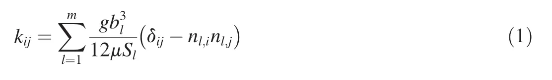
where kijis the equivalent seepage coefficient,i and j represent the directions of coordinate axes,m is the number of groups of cracks,Slis the spacing between fractures in group l,blis the equivalent hydraulic gap width of fractures in group l,nl,i(i=1,2,3)is the direction cosine of the normal direction of cracks in group l in regard to the i direction,μ is the kinematic viscous coefficient of the fluid,g is the gravitational acceleration,and δijis the Kronecker symbol.
2.2.Generalized equivalent continuum model for seepage field calculation
According to the continuity condition for water flow and the generalized Darcy's law (Kazemzadeh-Parsi and Daneshmand,2012),the mathematical model of the stable saturated seepage flow in the 3D generalized anisotropic equivalent continuous medium can be expressed with the following equation(Chen et al.,2011a,2012;Chen and Zhang,2016):
将我院2012年3月—2015年4月的54名护理人员选为研究对象,将其分为了观察组和对照组各27名。两组护理人员皆为女性,学历均在大专以上,观察组护理人员的平均年龄为(27.32±6.19)岁,平均工作时间为(5.94±3.67)年;对照组护理人员的平均年龄为(28.44±7.24)岁,平均工作时间为(6.21±3.39)年。两组护理人员的一般资料对比,差异无统计学意义(P>0.05)。
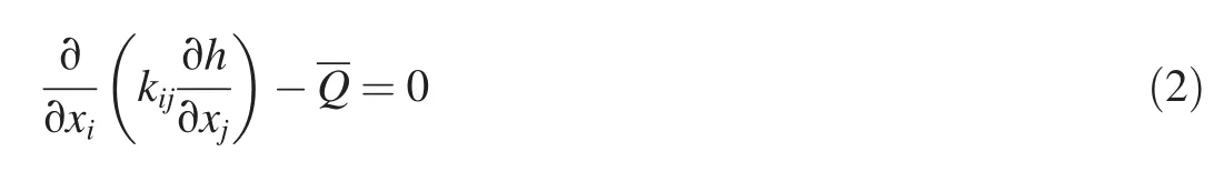
where xi(i=1,2,3)represent the 3D space coordinates;h=hc+z,where hcis the pressure water head,and z is the potential head;andis the source sink term in the seepage analysis area.
For non-pressure stable seepage problems with four types of boundary conditions(Chen et al.,2011a),the basic finite element iterative scheme of the node virtual flow method is as follows(Chen et al.,2012):

where K and K2are the amounts of seepage for the global and virtual domains of the computational area,respectively,after introduction of the boundary conditions;his the water head of unknown nodes;and Q and Q2are the flow rates of the global and virtual domains of the computational area,respectively,obtained with the known nodal water head,the internal source sink term,and the flow boundary.
2.3.Improvement of node virtual flow method
The virtual domain of the computational area contains two parts,i.e.,pure virtual elements and the virtual part of transition zone elements,of which the former is easy to solve,while the latter,which is divided into two parts by the free surface,is difficult to solve.In order to accurately simulate the virtual part of transition zone elements,a penalty function Fu(hc)of the pressure water head is introduced to improve the node virtual flow method.The equation is as follows(Zhang and Wu,2005):
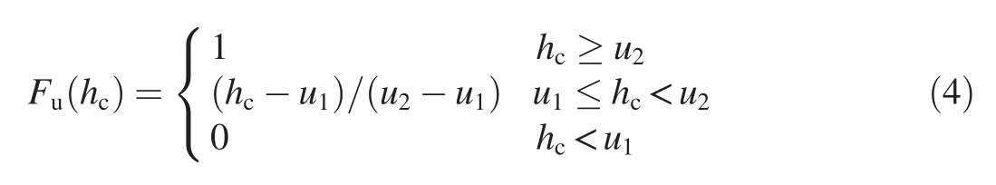
where u1and u2are the penalty parameters of the pressure water head,with u1<0 and u2>0.The penalty parameters are introduced to accurately calculate the external force or unbalanced force of different nodes,so as to improve the calculation accuracy and the rate of convergence.Detailed description of u1and u2can be found in Zhang and Wu(2005).
With the introduction of the penalty function,the isoparametric element conduction coefficient kεcan be obtained as follows:
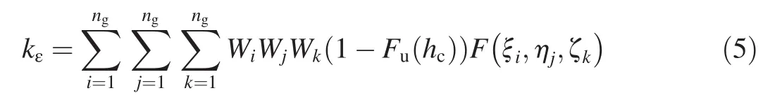
where ngis the number of Gaussian points in each coordinate axis;Wi,Wj,and Wkare weights for different coordinate axes,respectively;and F(ξi,ηj,ζk)is the integrand corresponding to the Gaussian point(ξi,ηj,ζk).
Eq.(5)can be used to simulate the virtual part of transition zone elements,and results with higher accuracy can be achieved.
3.Engineering application example
3.1.Project overview
The dam is located in a horizontal valley,dominated by sandstone.The terrain of the bank slope is relatively complicated,while the right and left sides of the dam are basically symmetrical.The thickness of the alluvial deposit on the flood bed is 10-20 m.The rock mass is weakly weathered,with a thin weathered layer.Two grade-III faults can be found on the left bank,and grade-IV structural faces,interlayer joints,and high-steep joints can be found on the right bank.The unloading action of the rock mass is strong,unloading cracks develop in layers in the weak unloading rock mass,and the interlayer rock mass is relatively dense.The water-proof rock mass is at significant depth,and the groundwater level is low.Along the dam axis,the distributions of the dam foundation rock mass,excavation line,and grouting layout are shown in Fig.2.According to geological survey and engineering experience under similar conditions,the main crack hydraulic parameters and statistics regarding the rock foundation are shown in Table 1.
3.2.Generalized equivalent continuum range
To improve the calculation accuracy,the generalized equivalent continuum range of the rock foundation(except for the fault)was divided into four types:a strong unloading zone,a weak unloading zone,a weak-weathered zone,and a slightly weathered zone-fresh rock stratum.The weak-weathered zone was subdivided into three layers,with 3 Lu≤q<5 Lu,5 Lu≤q<10 Lu,and q≥10 Lu,respectively(Fig.2).
In this study,we used the Snow model to determine the equivalent seepage coefficients for the weak-weathered zone and the slightly weathered zone-fresh rock stratum.The results are shown in Table 2.For the unloading zones in which cracks developed in different directions,the crack hydraulic parameters of the rock mass were difficult to obtain.Therefore,based on the measured values of seepage flow in the dam(Guo et al.,2016),the seepage coefficients were determined through inversion analysis(Zhou et al.,2015;Ren et al.,2016).
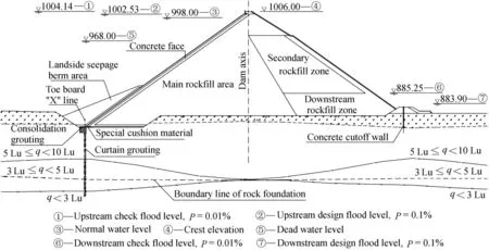
Fig.1.Typical profile of CFRD(units of water level and elevation:m).
3.3.Generalized equivalent finite element model
In this study,the main hydraulic structures of the dam were numerically simulated according to the original seepage control layout of the dam body.Of these structures,the dam's impervious structures(the concrete face,cushion,inverted filter layer,etc.),toe plate,high-toe wall,impervious wall,impervious curtain,new right and left bank curtains,and other important seepage control measures were accurately simulated,and a finite element mesh with an appropriate overall density and high quality was formed for 3D seepage field analysis.At the same time,the basic rock mass was divided according to the generalized equivalent continuum range.The left bank was extended 500 m away from the left dam abutment,while the right bank followed the fault zone of the Pudu River.The elevation of the bottom boundary of the model was set at 732.00 m,while the top elevation of the model was set at the crest elevation of the dam.A finite element model was established using hexahedral eight-node isoparametric elements(Fig.3),with a total of 197430 elements and 208018 nodes.The finite element mesh of the 3D model in the dam area was divided intensively to improve the calculation accuracy of dam seepage.
3.4.Inversion analysis of seepage field
The fractured rock strata with similar seepage characteristics were generalized,and the water level at the monitoring points was taken as representative of the local seepage characteristics.The seepage and water level monitoring values were found to be in agreement with the values of the generalized model.Thus,they were used for all the comparisons and verifications in the inversion analysis.The seepage coefficients of different material zones in the dam body are shown in Table 3.To assess the effect of the two grade-III faults on the left bank,the fault structure was modeled as a spatial thin layer with the equivalent continuum simulation method,and the seepage coefficient was set as 5.0×10⁻²cm/s based on previous experience.In the inversion analysis,we needed to determine the seepage coefficient of the unloading zone that significantly affected the seepage in the dam area.Since the cracks in the unloading zone developed in all directions,they could be regarded as isotropic materials.Through this inversion calculation,the following seepage coefficients were obtained:2.57×10⁻²cm/s and 2.98×10⁻⁴cm/s for the strong unloading zone and weak unloading zone,respectively.
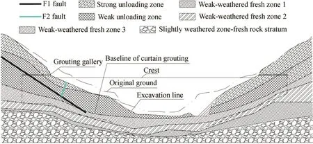
Fig.2.Distribution of rock mass in dam foundation.
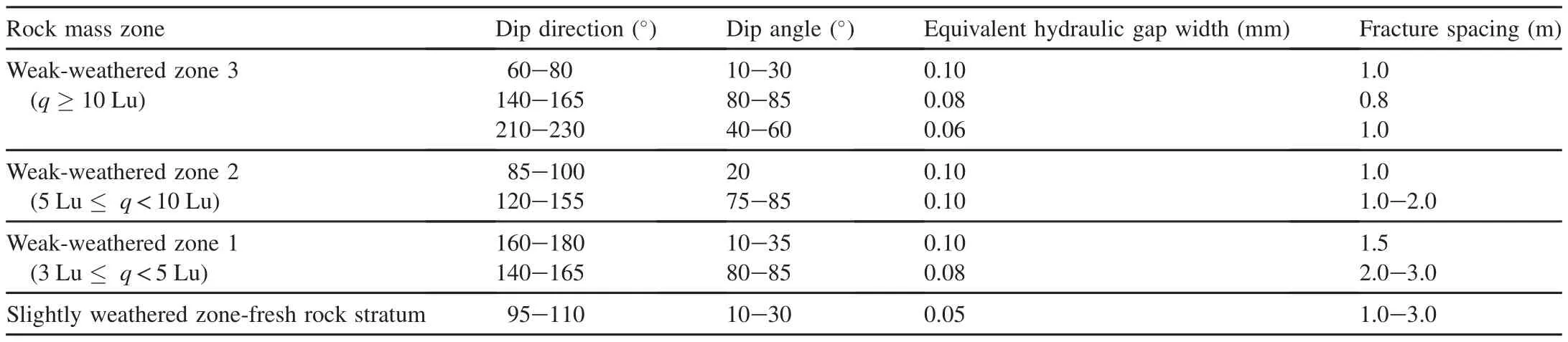
Table 1 Main crack hydraulic parameters and statistics regarding rock foundation.
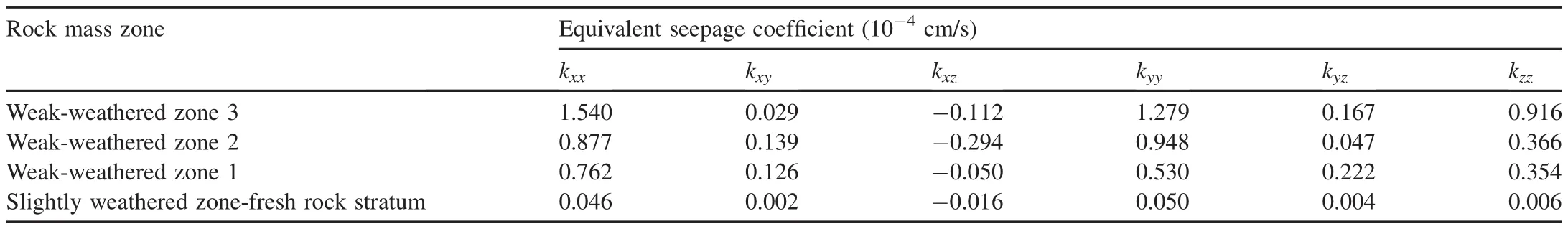
Table 2 Calculated results of equivalent seepage coefficients of weak-weathered zone and slightly weathered zone-fresh rock stratum.
Fig.4 compares the calculated results of the total seepage flow from inversion analysis and measurements taken during the reservoir impoundment process.The amount of the total seepage flow increased with the increasing upstream water level,and the calculated results agreed with the measured data,except at the upstream water level of 961.4 m.It should be noted that the downstream water level was invariable during the impoundment process,with a value of 877.00 m.
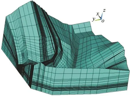
Fig.3.3D finite element model.
The calculated and measured values of the water level at monitoring points for verification are shown in Fig.5.Water level monitoring points 1 and 3 were located at the right side downstream of the dam,and water level monitoring points 2,4,and 5 were located at the right dam abutment,the left side downstream of the dam,and the left dam abutment curtain,respectively,as shown in Fig.6.Fig.5 shows that the calculated values of water levels at the monitoring points were close to the measured values in most cases,with a coefficient of determination R2greater than 0.9,except for the results at monitoring point 4,meaning that the seepage coefficients of the unloading zones obtained from inversion analysis were in agreement with the actual measurements,and could be used for inversion analysis of seepage flow under the normal water storage conditions.
3.5.Analysis of seepage characteristics of dam under normal water storage conditions
Under the normal water storage conditions,the water levels upstream and downstream of the dam were 998.00 m and 877.00 m,respectively.Seepage analysis was carried out usingthe generalized equivalent continuum model.From the results we can see the following:
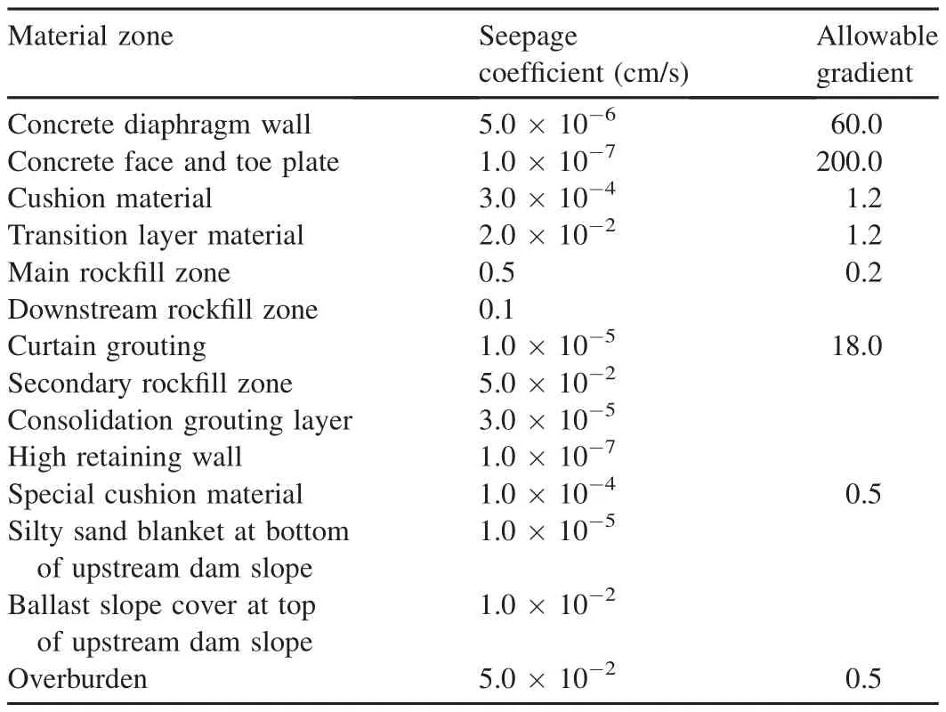
Table 3 Seepage coefficients of different material zones in dam body.
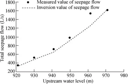
Fig.4.Comparison of calculated results of total seepage flow from inversion analysis with measured data.
(1)Fig.6 shows that the water levels at monitoring points 1 through 5 were 894.21 m,931.69 m,908.09 m,912.05 m,and 963.75 m,respectively.The water levels at the overflow surface downstream of the left and right banks were 883.10 m and 881.46 m,which were 6.10 m and 4.46 m higher than the downstream water level,respectively.The results show that there was a strong 3D seepage process in the dam area.
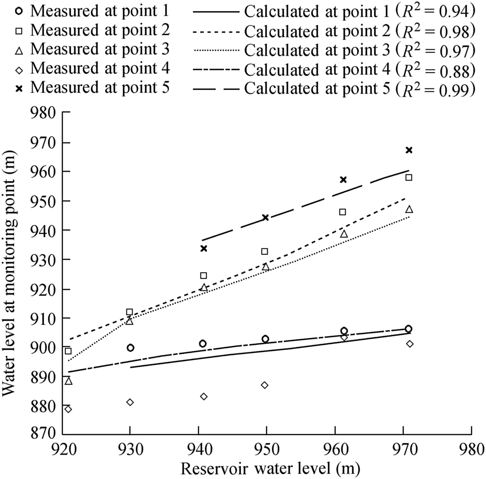
Fig.5.Comparison of calculated and measured values of water level at monitoring points.
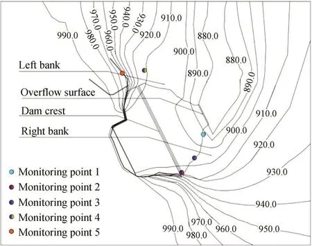
Fig.6.Water level distribution at elevation of 875 m in dam area under normal water storage conditions(units:m).
(2)After the reservoir was impounded to the normal water level,the total seepage flow in the calculation area was 2718.41 L/s,of which the seepage flow at the left and right dam abutments accounted for 89.1%.The left and right dam abutments became the main seepage regions in the dam area.The mountain on the left bank of the dam was relatively tall and the impervious curtain could effectively cut off the hydraulic connection of the fault,resulting in a controlled seepage flow of no more than 479.37 L/s.The mountain on the right bank was not as tall,and the strong unloading zone was below the water storage level at the right dam abutment.Even though there was an impervious curtain,due to the large difference between the water heads in front of and behind the curtain,the amount of seepage flow here was 1941.63 L/s,which was much greater than that on the left bank.The unloading zone in the dam foundation was small,with an impervious wall and a grouted curtain located below,so the seepage flow in the dam foundation was approximately 293.62 L/s,accounting for 10.8%of the total seepage flow.Covered by a concrete face with the function of seepage control,the dam body had the lowest seepage flow of 3.79 L/s.It can be seen from the results that the key seepage-proof measures of this project should focus on the left and right dam abutments,especially in the strong unloading zone at the right dam abutment.
(3)The water head contours can accurately reflect the seepage characteristics.The water head contours and seepage gradient distribution in the dam body under the normal water storage conditions are shown in Fig.7.The maximum seepage gradients in different material zones are shown in Table 4.It can be seen that under the normal water storage level,the free surface dropped quickly along the concrete face,with the maximum water head at the cushion layer under the concrete face being 886.45 m,which was basically stable in the rockfill zone.The concrete face,the toe plate,and the dam foundation impervious wall,together with the curtain under the wall,formed a closed seepage control system,effectively cutting off seepage flow at the upper part of the dam body.The maximum seepage gradient at the concrete face was 168.35,which was lower than the specified value.The gradients of other material zones in the dam area were relatively lower,and the values were within the designed allowable ranges.The impervious curtain in the maximum-height section was subjected to the maximum seepage gradient of approximately 16.89,which was close to the allowable value of 18.00.Therefore,the construction should ensure its quality and durability.The seepage gradients at the downstream overflow surface on the left and right banks were very low and nearly equal to 0.6.The analysis described above shows that the seepage control measures could meet the seepage stability requirements.
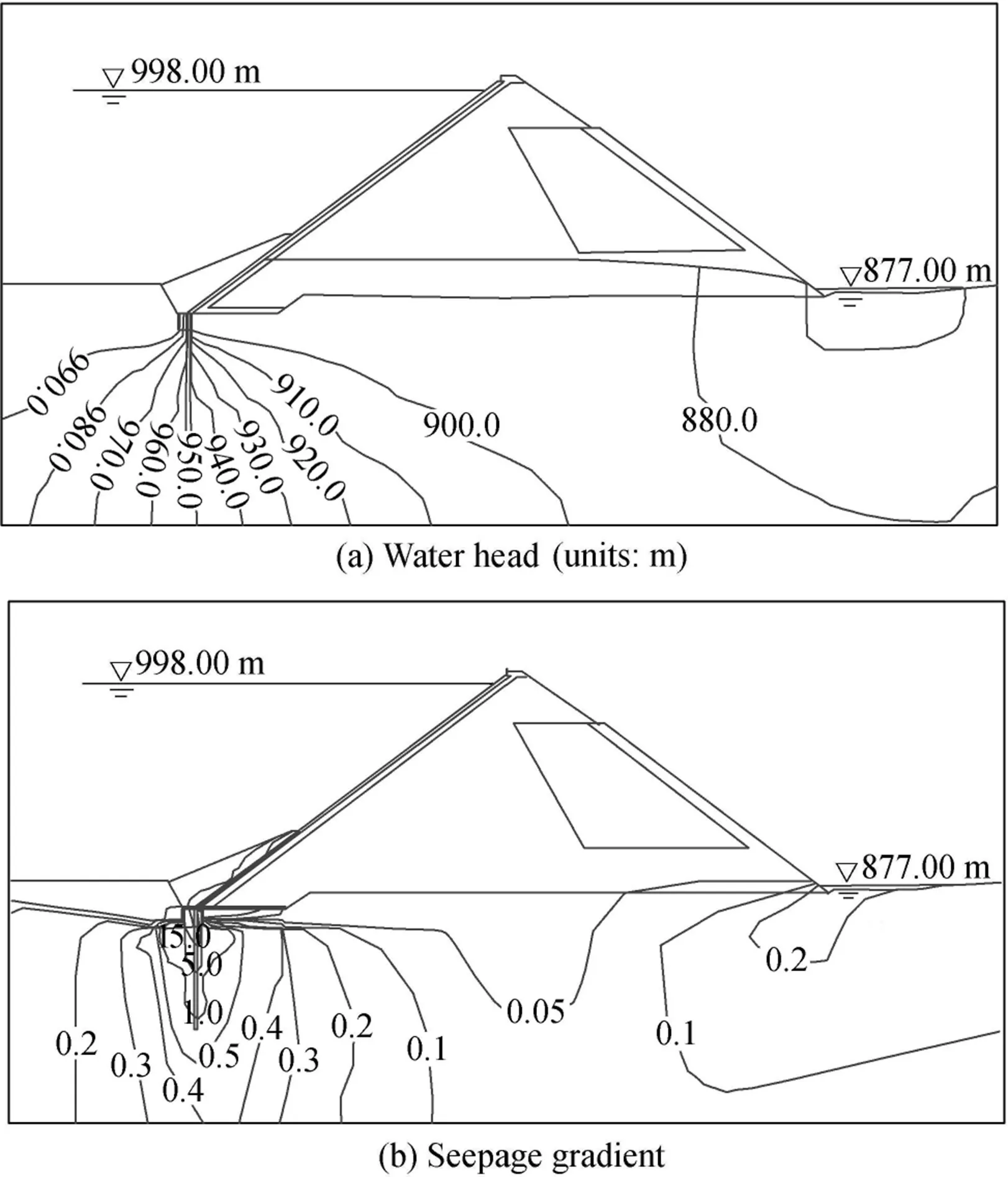
Fig.7.Water head contours and seepage gradient distribution in maximum-height section under normal water storage conditions.
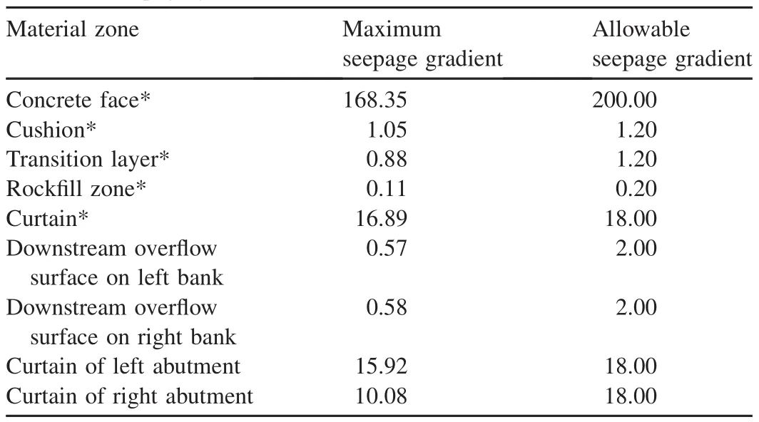
Table 4 Maximum seepage gradients in different material zones of dam.
4.Conclusions
(1)The generalized equivalent continuum method for seepage analysis can satisfactorily solve the seepage problem of CFRDs.It is an effective method for finite element analysis of the seepage field of CFRDs in the dam foundation with developed structural faces.
(2)The key to the generalized equivalent continuum model is to determine the equivalent seepage coefficient in different ways for different material zones.In this study,the equivalent seepage coefficients of the weak-weathered zone and the slightly weathered zone-fresh rock stratum were calculated using the Snow model based on the statistical data of the crack hydraulic parameters.The equivalent seepage coefficients for the unloading zones in which cracks developed in different directions were determined through inversion analysis with the seepage monitoring data at different water levels.This more realistically reflected the fractured rock mass seepage characteristics with strong operability.
(3)Due to the high permeability of rock mass in the dam foundation,there was a large difference between the water heads in front of and behind the impervious curtain,leading to large seepage gradients,with the maximum value of 16.89.Meanwhile,the dam foundation and the left and right dam abutments were major seepage regions in the dam area.The seepage problem at the dam abutments was the most serious,with the seepage flow there accounting for approximately 89.1%of the total amount.Therefore,during the design and construction of CFRDs,attention should be paid to the seepage problem in the dam foundation and at the left and right dam abutments when the dam foundation is stratified and more cracks develop in the rock mass.
(4)Through calculation of the 3D seepage field,the positions of the rock stratum with large amounts of seepage flow in the dam area were determined,providing an important basis for seepage control.
猜你喜欢
杂志排行

Water Science and Engineering的其它文章
- Application of a hybrid multiscalar indicator in drought identification in Beijing and Guangzhou,China
- On relationship between curve numbers and phi indices
- Analysis of influence of observation operator on sequential data assimilation through soil temperature simulation with common land model
- Common effluent treatment plant(CETP):Reliability analysis and performance evaluation
- Disinfection of dairy wastewater effluent through solar photocatalysis processes
- Numerical study of hydrodynamic mechanism of dynamic tidal power