Hydroelasticity of a Barge with Varying Bathymetry
2018-10-12LUYeTEMARELPandeliZHOUYeTIANChaoWUYousheng
LU Ye,TEMAREL Pandeli,ZHOU Ye,TIAN Chao,WU You-sheng
(1.China Ship Scientific Research Center,Wuxi 214082,China;2.University of Southampton,Southampton SO16 7QF,UK)
Abstract:The uneven and complex seabed bathymetry is the greatest feature of the marine environment close to the reefs.In this paper,the three-dimensional(3D)hydroelasticity analysis with varying shallow water depth is used to calculate the wave-induced motions and loads of a floating barge,considering the non-uniformity of the seabed.The influence of the complex seabed topography is investigated by comparison to uniform seabed representation.Through modal summation the 3D hy droelasticity analysis provides predictions of wave-induced loads,such as bending moments and stresses,in regular waves,as well as design waves.These predicted wave loads show that modelling the non-uniform seabed has a significant effect on the floating structures’service near islands,depending on water depth and seabed variability.Use of parallel computing which is very suitable in dealing with the large number of calculations involved in the hydrodynamic modelling of the complex fluid-structure interaction system,has significantly reduced CPU times.
Key words:3D hydroelasticity;varying bathymetry;shallow water;parallel computing
0 Introduction
Accurate prediction of the responses of floating bodies in complex and variable environments is important for their safety assessment.This is particularly important for varying and complex bathymetry.Commercial hydrodynamic software,such as AQWA and SESAM,is not suitable for calculating the motions and loads of floating marine structures operating in environments with non-uniform water depth.In traditional potential analysis,bathymetry of the bottom is assumed to be uniform.However,the uneven seabed affects the motion and loads of the floating structures.Therefore,prediction of wave-induced motions and loads and structural safety evaluation need to be carried out under realistic environmental conditions.
The theory of three-dimensional(3D)linear hydroelasticity has been proposed by Bishop,Price and Wu[1]and the 3D hydroelastic analysis is already mature in the case of infinite and uniform water depth.The influence of non-uniform seabed has been investigated by many researchers,beginning with simple submersible shapes.For example,a semi-cylindrical structure of 150 m length and 4m radius in uniform 6 m water depth,has been examined by Dewi et al[2].Athanassoulis and Belibassakis[3-4]calculated the two-dimensional(2D)hydroelastic characteristics of an elastic thin plate in shallow water with uneven seabed,while Gerostathis et al[5]studied its 3D characteristics.Adrianov and Hermans[6]assessed the influence of various parameters,such as wavelength and wave direction,on the 2D hydroelasticity of very large floating structures(VLFS)in infinite and shallow waters.Sun et al[7],Lv et al[8]and Song et al[9]carried out model tests of VLFS considering the impact of the underwater bathymetry in regular and irregular waves.The uneven seabed is modelled by using a variety of sand dunes,of cylindrical and elliptical form,in the bottom of the wave basin.Kyoung et al[10]designed four different seabed arrangements to calculate the hydroelastic effects of very large floating bodies.Buchner[11]studied the influence of the seabed topography on ship motions by modelling the seabed as a second fixed body.He discussed the importance of having sloping boundaries for this second body rather than vertical walls.Using the aforementioned model[11],the necessity for using sloping boundaries for the modelled seabed terrain was verified by Ferreira et al[12].Hauteclocque et al[13]also assumed that the seabed topography is modelled as a second body fixed in the hydrodynamic analysis and obtained more accurate results of the motions and responses of ships.Utsunomiya et al[14]compared the hydroelastic responses of a box-type VLFS in uniform seabed,a seabed with 1/75 slope and a seabed with variable depth.Pinkster[15]proposed a simplified method for the hydrodynamic calculation of single-slope submarine terrain boundary,suitable when the mooring of multiple ships near the dock can be divided into multiple areas.The aforementioned studies,as can be seen,have all used simple shapes for the bathymetry rather than more realistic seabed topography.
Four decades after its inception,the software THAFTS(Three-dimension Hydroelastic Analysis of Floating and Translating Structures)has proved to be a powerful tool for predicting wave-induced motions and loads of floating structures and validated by full-scale measurements and model tests.Considering non-uniform environmental conditions,Wu et al[16-17]and Tian et al[18-19]have further developed the three-dimensional linear hydroelasticity of large-scale floating bodies to account for the wave inhomogeneity,the variable water depth and the multi-module fluid-structures interactions.Li et al[20]investigated the dynamic behaviour of a VLFS in the relatively flat sea region in the middle of a lagoon surrounded by reefs.Yang et al[21]and Lu et al[22]used the same method to examine the motions and loads of the floating structures in non-uniform water depth and near-island reef environment and pointed out that the design load prediction considering the complexity of the seabed topography was important.These results were obtained using parallel computing in conjunction with the Message Passing Interface(MPI)on the ‘Shenwei TaihuLight’ supercomputer.
In this paper,the 3D hydroelastic analysis software THAFTS,with the aforementioned parallel computing method,of floating structures in uneven seabed is demonstrated using a stationary barge as an example.The seabed is modelled as the second fixed body to solve the equations of motions of the stationary barge structure in this complex environment.Two cases of water depth are considered,namely 30 m and 10 m.For each of these cases the seabed is modelled as uniform using the relevant no flow condition at the seabed,and as non-uniform using the second fixed body.The predicted responses include heave and pitch motions and amidships vertical bending moment in regular head waves.Furthermore,the same method is applied using an Equivalent Design Wave(EDW)and illustrating direct stress distribution on the barge.
1 Hydroelastic analysis method of a floating body
1.1 Brief description of the 3D linear hydroelasticity theory
The hydroelastic analysis of the barge is defined in a Cartesian coordinate system Oxyz,with x-axis positive to bow,x-y plane on the undisturbed water surface,z-axis pointing upwards and passing through the centre of gravity of the barge.Introducing the principal coordinates pr(t)(r=1,2,…,m),the displacementof the barge is expressed as a summation over the principal modes)of the floating structure in vacuo,namely.

In this equation r=1,2,…6,correspond to rigid body motions of surge,sway,heave,roll,pitch and yaw respectively and m denotes the total number of principal modes allowed in the analysis.The generalized equations of motion are represented in terms of prin the matrix form as follows:

where[a],[b]and[c]are the generalized mass,structural damping and stiffness matrices of the dry structure and[A],[B]and[C]are the generalized added inertia,hydrodynamic damping and fluid restoring matrices,respectively.{p}represents the principal coordinate vector and}is the generalized wave forcevector,containing both incident wave and wave diffraction contributions.
The potentials Φ comprises the incident potential φI(t),diffraction potential φD(t)and radiation potentialAll potentials satisfy Laplace’s equation and the free surface,seabed,and far-field boundary conditions.The pulsation source Green’s function is used for the radiation potentials.
The principal coordinates are obtained in regular waves(frequency domain analysis)and the deformations and internal forces,such as bending moments and stresses,are obtained using modal summation.For instance,the vertical bending moment about y-axis at a cross-section along the structure is

and the longitudinal direct stress at a defined point (x,y,)zon the section is

In these equations,σxrand Myrrepresent the modal longitudinal direct stress and modal vertical bending moment for the r th mode shape,respectively.
When a floating structure is deployed in shallow water,the encountered wave conditions and the structural responses may be greatly influenced by the varied seabed topography.In such a complicated geographic environment,the characteristics of wave evolution must be clarified,and the corresponding hydroelastic analysis approaches must be developed.
When the barge is deployed in shallow water close to the island,the complex seabed can be represented as a fixed boundary.To account for the influence on the diffraction and radiation,the boundary conditions on the non-uniform seabed,represented by the second fixed body,become:
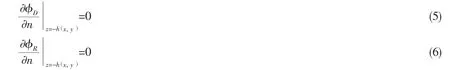
Equations(5-6),as can be seen,are applied to variable water depth and appropriate to the uneven seabed topography.
1.2 Parallelization computing
In addition to the complex shape of the floating structure,the fluid domain contains a nonuniform shallow water environment.Therefore,a large number of panels to discretise floating structure-fluid interface and non-uniform seabed are required.Usually,a larger extent of the seabed needs to be modelled by comparison to the floating structure.Furthermore,as the seabed does not possess port/starboard symmetry as typical conventional ships,the number of panels are much larger than those of the floating body,thus increase the calculation effort.Therefore,the analysis process is very slow when using a serial code,exacerbated by the number of distortion modes included and wave frequencies for which the analysis is carried out.
Accordingly,the MPI and multi-level parallel programming model are used,focusing at the(wet)panels,the wave frequencies,and so on,rather than the existing serial THAFTS program.The calculations were performed on the ‘Sunway TaihuLight’,which is ranked 1 in the current TOP500 supercomputer list(top position in 06/2016,11/2016,06/2017 and 11/2017).This is a system developed by China’s National Research Center of Parallel Computer Engineering&Technology(NRCPC)and installed at the National Supercomputing Center in Wuxi.Using the aforementioned high-performance computing facilities,the calculation times decreased significantly for the 3D linear hydroelastic motions and structural dynamic responses of the barge with the non-uniform seabed conditions in the near-island environment.
2 Structural and hydrodynamic modelling
2.1 Structural model
The principal particulars of the barge are shown in Tab.1.A typical fully loaded condition is selected for the analysis.The 3D structural model,as shown in Fig.1,was generated by suitable beam and shell finite elements.A total of 70029 elements were used for the whole barge structure,in the MSC.Patran software,to model major structural components such as deck,side shell,double bottom,transverse bulkheads,longitudinal girders,superstructures,etc.
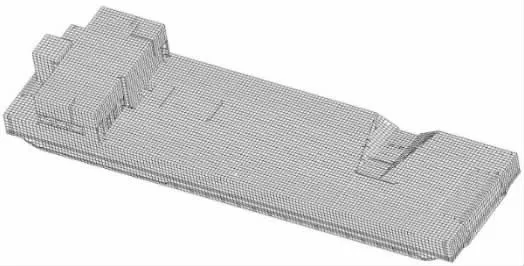
Fig.1Structural FE model of the barge comprising 70029 elements in total
The Lanczos method was selected to obtain the eigenvalues and eigenvectors.The first four natural frequencies and mode shapes,of the vessel freely vibrating in vacuo,are shown in Fig.2.A total 30 distortion modes were included in the analysis,i.e.m=36.
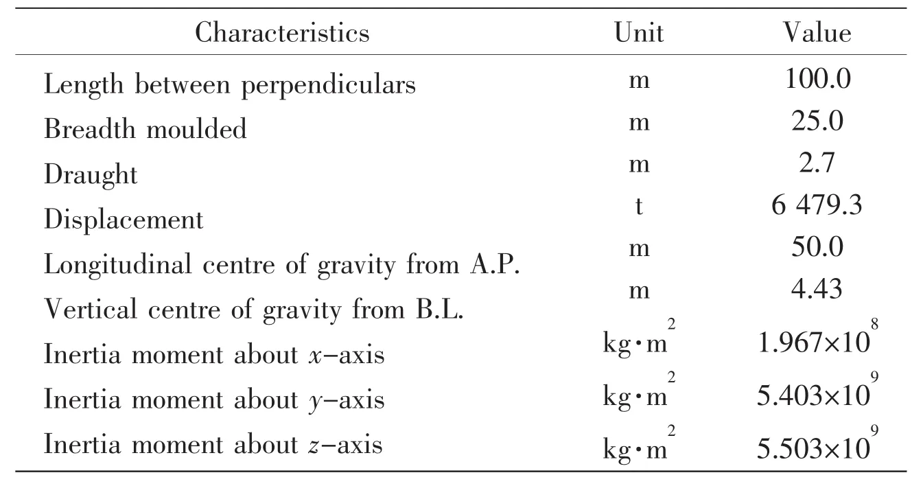
Tab.1 Principal particulars of the barge
The vehicle ramp situated near the fore quarter,and the superstructure disrupt the port starboard symmetry,as can be seen in Fig.1.However,as can be seen from Fig.2,these small asymmetries have very little effect on the symmetric nature of the 2-node or 3-node vertical bending modes or the antisymmetry of the 1-node twisting and 2-node horizontal bending modes.Therefore,the conventional definition for port-starboard symmetric structures is still used.Accordingly,the principal mode shapes of this barge were defined as symmetric(2-node and 3-node vertical bending)and antisymmetric(1-node torsion and 2-node horizontal bending).The coupling between torsion and horizontal bending is relatively small and inherent in the 3D finite element model.
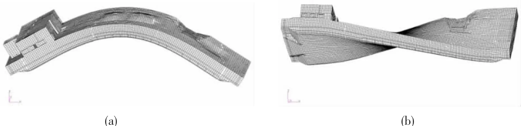
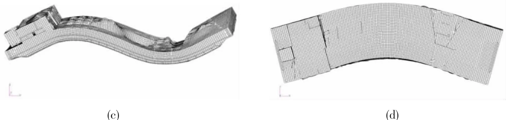
Fig.2 The first four flexural mode shapes of the barge and corresponding nature frequencies(a)2-node vertical bending(r=7),2.038 Hz;(b)1-node torsion(r=8),3.024 Hz;(c)3-node vertical bending(r=9),4.475 Hz;(d)2-node horizontal bending(r=10),5.141 Hz
2.2 Hydrodynamic model
Located in shallow water near a reef,the seabed is non-uniform.In order to ascertain the effects of varying bathymetry on the dynamic behaviour of the floating barge,two models of the environment were used,i.e.(i)uniform seabed and(ii)seabed with varying topography modelled as a second fixed body.For the latter only the local terrain range was modelled,under the assumption that this is the seabed region which will affect the motions and loads of the floating body.This also reduces the amount of calculations performed.The selected seabed has length of 200 m and width of 120 m,along the x and y axes,respectively as per the floating barge.The topography of the seabed is completely submerged with the fixed body boundaries sloping smoothly.The seabed topography corresponds to real seabed data near reefs.Two depths are considered corresponding to vertical distances between the seabed and the barge centre of gravity of 30 m and 10 m.There are 3 476 four-cornered or three-cornered wet panels on the barge(whole of the barge)wetted interface.There are 9 792 panels on the seabed,as shown in Fig.3,nearly 3 times of the floating body.It should be noted that the normal points are out to the flow both for the barge and the second body representing the seabed.The hydrodynamic model of the barge/seabed system with complicated terrain is shown in Fig.3.
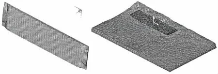
Fig.3 Hydrodynamic model of a barge including bathymetry of seabed
3 Results and discussion
3.1 Influence of water depth and bathymetry
For the analysis in this paper the barge is stationary in regular head waves.Using the serial code in a typical workstation requires 6.5 hours to complete the calculations for one wave frequency.On the other hand,the same calculation is carried out in 100 s CPU time on the supercomputer using parallel computing with MPI.
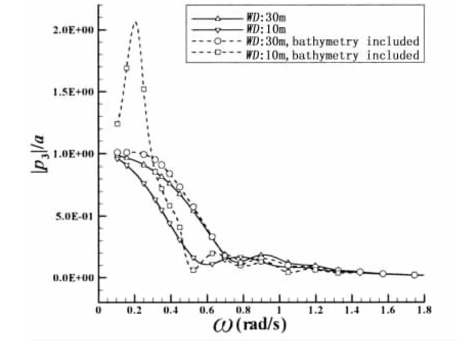
Fig.4 Comparison RAOs of heave motion at different water depths
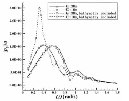
Fig.5 Comparison RAOs of pitch motion at different water depths
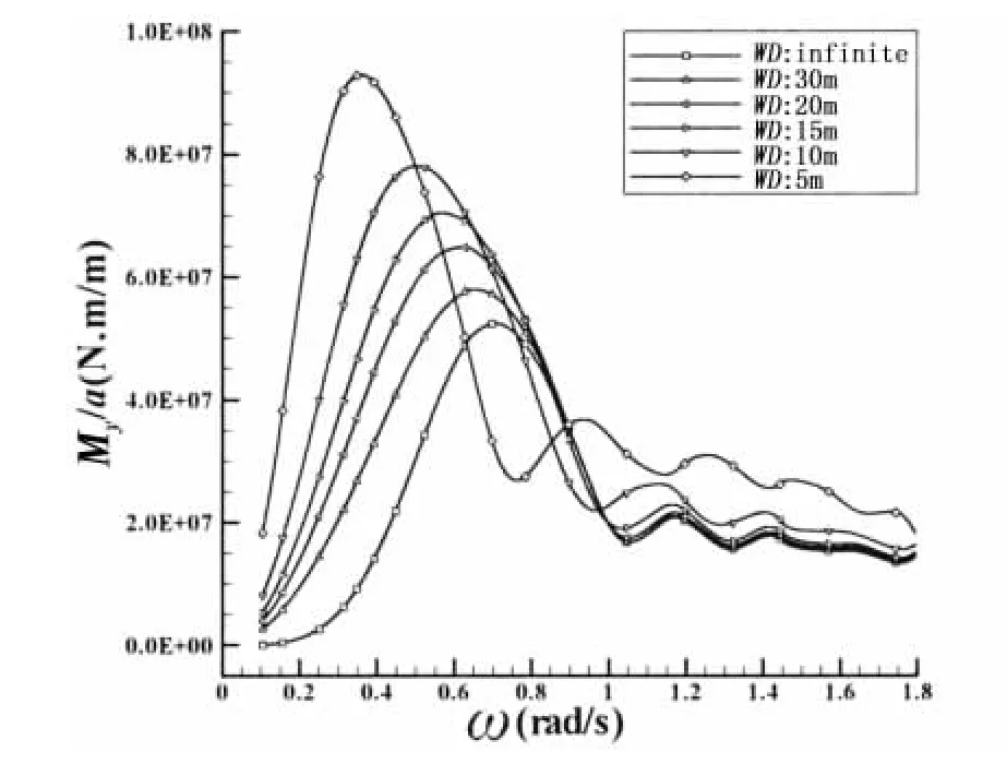
Fig.6 Comparison of RAOs of VBM at amidships at different uniform water depths
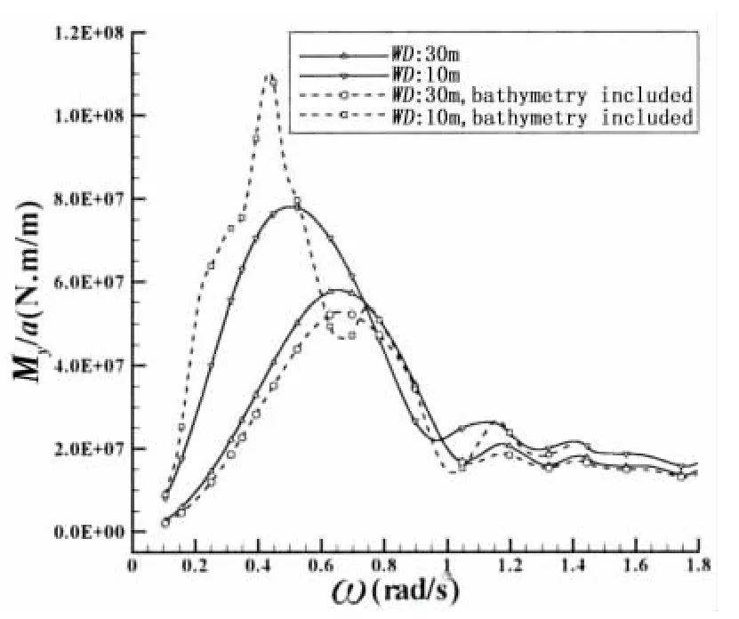
Fig.7 Comparison of RAOs of VBM at amidships with uniform&non-uniform seabed
The heave and pitch motions of the barge in head regular waves of unit amplitude are shown in Figs.4 and 5,respectively,as a function of the wave frequency ω.The response amplitude operator(RAO)of the amidships vertical bending moment(VBM)of the barge in head waves is shown in Figs.6 and 7.Both uniform and complex seabed topographies are included for 30 m and 10 m water depths.
Considering uniform seabed,heave RAOs show a decrease with decreasing water depth in low wave frequencies.Pitch RAO peaks appear to be unaffected by changes in the uniform water depth.Similar trends for heave and pitch RAOs were observed by Feng et al[23]who investigated the influence of depth using the commercial software WADAM,as well as Buchner’s calculations[11].On the other hand,amidships VBM RAO peaks increase with decreasing uniform water depth.Furthermore,the peak of VBM and pitch RAOs are observed at lower wave frequencies with decreasing uniform water depth.This implies that the conventional ship-wave matching concept in infinite water depth,is affected considerably by decreasing water depth.
The influence of the non-uniformity of the seabed is dependent on the water depth itself,as can be seen from Figs.4,5 and 7.For the 30 m water depth the non-uniformity of the seabed has small influences on heave and pitch RAOs.This is also true for the amidships VBM RAO,which has a smaller peak for the non-uniform seabed compared to the uniform seabed case.At this depth the non-uniformity of the terrain does not influence the wave frequency at which pitch and VBM RAOs peak.On the other hand,for the 10m water depth significant increases are observed in the heave and pitch RAOs and amidships VBM RAOs,the former almost doubling the heave and pitch RAO peak and the latter showing a nearly 50%increase in the peak value.It should be noted that the numerical predictions by Buchner[11],for 15 m nonuniform water depth also show similar increases in heave and pitch RAOs in relatively low wave frequencies.It is also observed that the non-uniformity of the seabed results in a peak for the heave RAO,albeit at a wave frequency lower than that for the peak pitch RAO.The wave frequencies at which the pitch and amidships VBM RAOs peak also become smaller as a result of the non-uniformity.
3.2 Short-term extreme value forecast
According to measured data in the target sea area,the Jonswap wave spectrum is applicable to the limited wind area,namely

where the generalized constant of Jonswap spectrumis the significant wave height,ω and ωpare the wave and peak frequencies,respectively,and g is the gravitational acceleration.γ is a non-dimensional peak shape parameter which follows a Gaussian distribution with mean value of 2.0,according to the measured statistical data and σ is a numerical parameter,σ=0.07( ω≤ωp).
Although this barge may be subjected to a variety of external loads,the wave-induced load is the main part of the external loading and plays a decisive role in the assessment of the longitudinal strength.In this paper,the wave load is calculated by the equivalent design wave method.
The design parameters of the barge for three peak periods Tpare given in Tab.2,for significant wave height Hs=4 m.Head and following waves are denoted by 180°and 0°,respectively.The peak RAO of vertical bending moments and shear forces(VSF),amongst different wave directions,always occurred at 0°and 180°;hence,only these two angles are compared in Tab.2.The EDW parameters are also provided in Tab.2.
Tab.2 Equivalent design wave parameters
3.3 Stress distribution
Using the equivalent design wave parameters,the stress analysis of the barge is carried out directly by hydroelastic method.It is not necessary to apply the corresponding external load to the structural model,basically,used in the traditional method.A hydroelastic analysis is carried out using the properties of the EDW,in water depth of 30 m with non-uniform seabed,and evaluating the stresses using Eq.(4).
The results,presented in Fig.8,show that the direct stresses at amidships are larger than other positions along the barge.In addition,considering EDW2 shear forces,hence shear stresses,at the aft quarter section(L/4)are maximum.
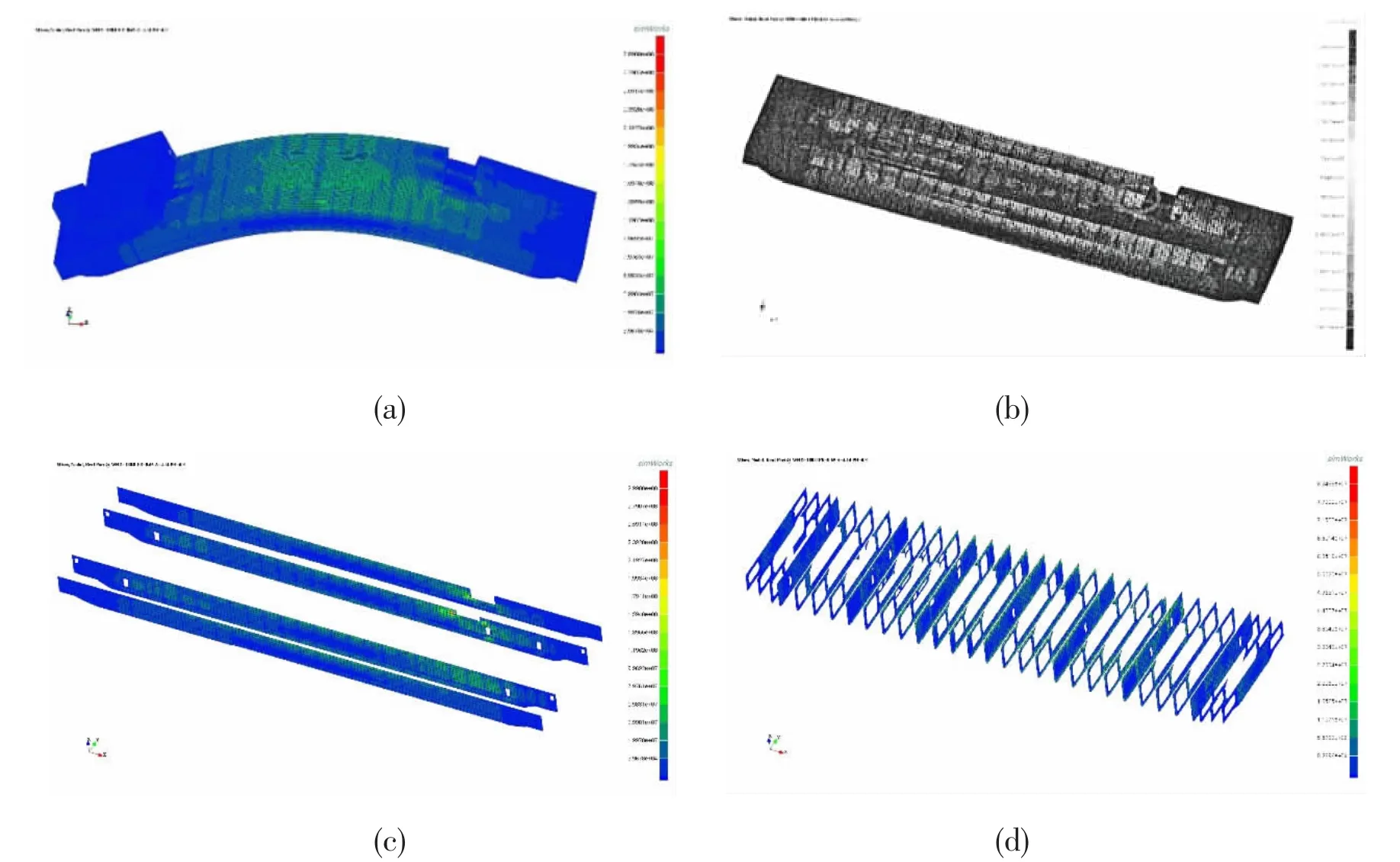
Fig.8 Direct stress distribution of the barge in EDW2(a)The whole structure;(b)The structures under the deck;(c)Longitudinal bulkheads;(d)Transverse bulkheads
4 Conclusion and discussion
In this paper,the subject of a floating body operating near islands together with non-uniform seabed topography is investigated by using 3D linear hydroelasticity.This is an important problem,considering increases in offshore operations and the associated complexity of the seabed.
In the absence of commercial software which can predict the performance of floating marine structures operating near reefs,including varying bathymetry,3D hydroelastic software THAFTS has been further developed to perform such an analysis.
In this paper,the motions and vertical bending moments of the barge,stationary in head waves,in uniform and non-uniform seabed terrains were compared.Based on these predictions,it is concluded that the influence of the uneven seabed is significant enough to be considered when marine structures are deployed near islands and reefs in shallow water,e.g.of the order of 0.1L.Further investigations are necessary to understand the influence of the seabed topography on different wave-induced motions and loads,particularly as a function of the amount of non-uniformity in the seabed topography.
Furthermore,the current method,which allows for non-uniformity of seabed,has been applied to an equivalent design wave showing the complexities involved in EDW parameters in terms of bending moments,shear forces and wave direction.
The hydrodynamic models used include complex bathymetry,hence require very large number of panels when modelling the floating body and the seabed,the latter as a second fixed body.Use of the Sunway TaihuLight supercomputer,currently having the fastest computing speed,has significantly improved the CPU time used combined with parallel computing and the MPI method.
Acknowledgment
The work was supported by the Ministry of Science and Technology with the research project(Grant No.2017YFB0202700)and the Ministry of Industry and Information Technology with the research project in the field of high-tech ships.
杂志排行

船舶力学的其它文章
- Numerical Calculation of Hull Wave-making Resistance by Three-dimensional RANS Method
- Mathematical Representation of a 3-D Translating Source Green Function and its Fast Integration Method
- Measures to Restrain Propeller-Hull Vortex Cavitation and Some Discussions
- Evaluation of Turbulence Models for the Numerical Prediction of Time-dependent Cavitating Flow During Water Entry of a Semi-closed Cylinder
- Investigation on Higher-Order Responses of Vortex-Induced Vibration for a Mounted Cylinder
- Dynamic Property and Motion Simulation of Atmospheric Diving Suit