Numerical Calculation of Hull Wave-making Resistance by Three-dimensional RANS Method
2018-10-12HUJunmingLITieliJIANGXiaoningLINYanXUXuefeng
HU Jun-ming,LI Tie-li,JIANG Xiao-ning,LIN Yan,XU Xue-feng
(1.School of Naval Architecture and Ocean Engineering,Dalian University of Technology,Dalian 116024,China;2.Department Directly under the Naval Equipment Department,Beijing 100841,China)
Abstract:According to the cause and classification of hull resistance,a three-dimensional RANS method is proposed to solve hull wave-making resistance.Compared with Rankine source method which is on the basis of potential flow theory,it is turned out that this proposed method is of higher numerical accuracy in solving wave-making resistance,and its result shows good agreement with EFD method.The values of shape factor(1+K)at different Froude numbers are basically the same,with slight deviation.The values of wave crest on the bow and sides are bigger than those obtained by Rankine source method,while the values of wave trough are opposite.Changing tendency of wave profile agrees with that of Rankine source method,and as the increase of Froude number,the Kelvin wave system is becoming more obvious and the wave crest moves backwards.The three-dimensional RANS method is proved to be appropriate for engineering application.
Key words:three-dimensional RANS method;Rankine source method;1+K;wave resistance;wave profile
0 Introduction
Resistance performance is significant among ship performances(such as floatability,stability,and rapidity).And the prediction of hull resistance has always been an important research point,and free surface wave is highly concerned by ship industry.
Experimental Fluid Dynamics(EFD)is of high accuracy and strong practicability in predicting hull resistance,nevertheless,during the experiment,some assumptions are proposed to simplify problems,and in the process of determining shape factor 1+K,flow instability and wave disturbance in towing tank have a certain influence on the measurement of wave-making resistance.Wave-making resistance research based on potential flow theory has gone through a process from linearity to nonlinearity.In 1898,Michell linked hull form functions to wave-making theory and proposed thin ship theory,which laid the foundation for the theory of linear wave-making[1].In 1964,Hess Smith applied panel method to solve three-dimensional infinite fluid field,which brought wide application of panel method in ship hydrodynamics[2].In 1977,Dawson put forward a method to calculate linear wave resistance on the basis of Rankine source method.It is flexible,simple and very easy to generalize.His method made it possible to progress linear wave-making theory to nonlinear wave-making theory by perturbation theory[3-5].However,there is still some limitations in the method based on potential flow theory because of the incapability to consider the effect of viscosity,wave breaking,vortex separation and slapping.As the society development and technique innovation,RANS method is on the rise in ship flow filed calculation.Compared with potential flow theory method,fluid medium of RANS method is more real,and viscosity is also taken into consideration,it is able to solve some problems that have been hard to overcome since the development of potential flow theory.With high accuracy and wide usable range,RANS method has been a significant method to research hull resistance[6-9].
This paper applies two methods including viscosity flow and potential flow to obtain wave-making resistance.According to viscosity flow theory N-S equation,a numerical calculation method of solving hull wave-making resistance based on three-dimensional RANS method is put forward,by calculations of viscous double-body flow,non-viscous double-body flow,and viscous free-surface flow,numerical results match well with EFD method,and its numerical accuracy is higher than Rankine source method which is based on potential flow theory.The wave profile is consistent with characteristics of Kelvin wave system.It is turned out by numerical results that researching wave-making problem by three-dimensional RANS method is more practicable.
1 Rankine source method
The numerical computation program for solving hull wave-making resistance is compiled under the following assumptions:the ship is assumed to sail on the free surface in a uniform speed U as shown in Fig.1,the X-axis and Y-axis are located in undisturbed free surface,the origin of the co-ordinate system is located in an undisturbed free surface at amid ship,the direction of X-axis is the same as flow direction and the Z-axis is vertically upwards[10].
The total velocity potential Φ is the sum of the double-body velocity potential Φrand wave-making perturbed velocity potential Φw,namely,

The total velocity potential Φ needs to satisfy the following boundary conditions:no wave radiation condition ahead,Laplace equation,solid boundary condition and the dynamic and kinematic conditions on the free surface.The detailed expressions are described as follows:
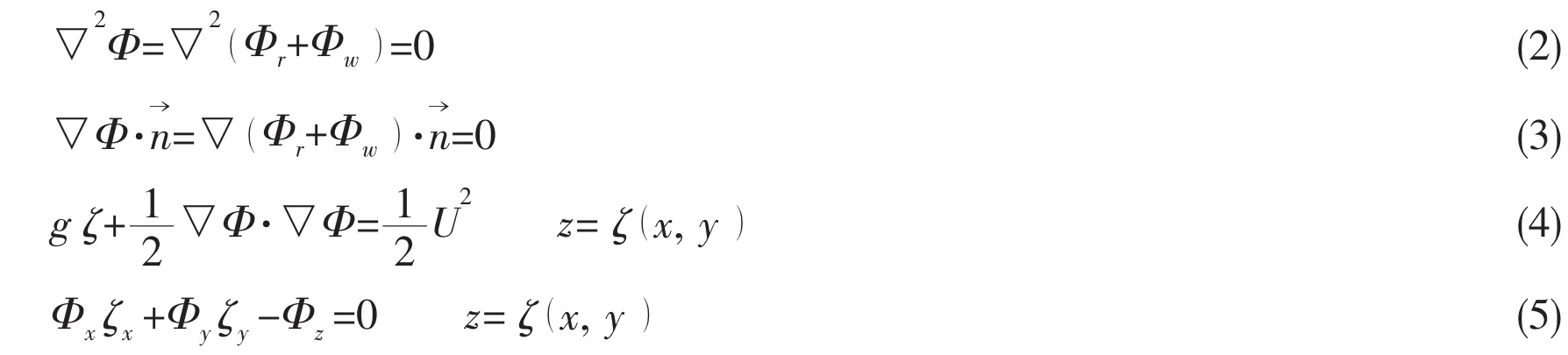

The flow fluid of the double-body is symmetric about the still water surface,the boundary conditions of which can be expressed as follows:

Compared with double-body velocity potential Φr,the wave-making perturbed velocity potential Φwis a small quantity.Substituting Eqs.(1)and(7)into Eq.(6),ignoring the higher order term of Φw,the linear boundary condition of free surface can be obtained.

where l is the differential of velocity potential along streamline on the symmetric plane z=0.Rankine sources can be distributed on hull surface SBand undisturbed free surface SFbased on Rankine source boundary element method,then,
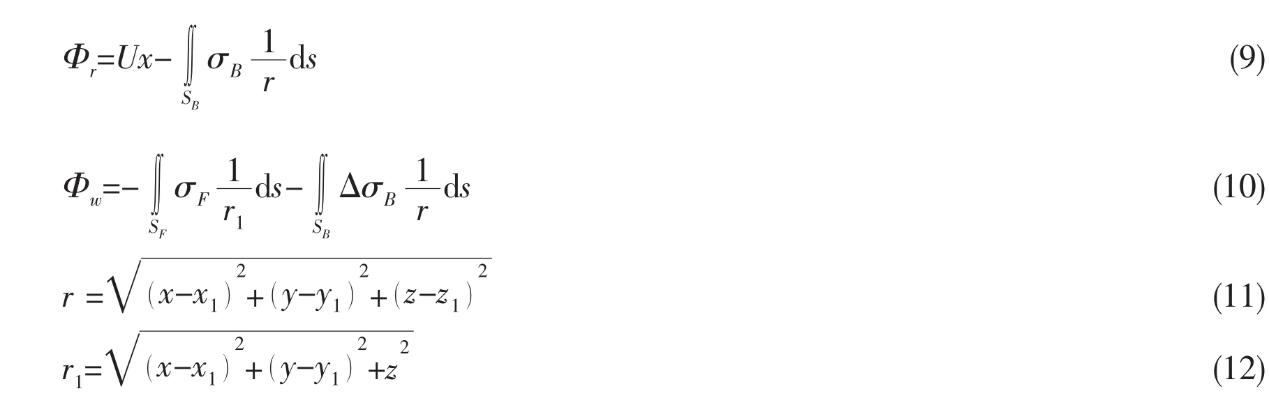
where r and r1are the distances between source points(x1,y1,z1),(x1,y1,0)and field point(x,y,z),respectively.The flow past the double-body is obtained from the numerical solution of a boundary value problem subjected to the Neumann boundary condition on the double-body hull.If the hull surface SBis divided into NBsurface elements,the discretized system of linear equations for double-body velocity potential Φris shown as follows:

The source intensity σBon each control point of the hull surface can be obtained by solving the system of linear equations above.And then the velocity potential Φrand the streamline distribution past the double-body flow can be calculated.
If the free surface is divided into surface elements,the discretized system of linear equations for perturbation velocity potential Φwfulfilling the solid boundary condition and linear free-surface condition is shown as below:
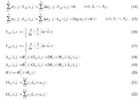
where enis the upstream finite difference operator at point N.Since the system of linear equations above is fully populated and asymmetric,and that the diagonal is not dominant,the Guassian elimination method is used to obtain the discretized source intensity on the hull surface and still water surface.Then the perturbation velocity potential can be calculated.The pressure distribution over the hull surface can be calculated from Bernoulli equation fulfilling free-surface condition.The wave-making resistance can be obtained by integrating the pressure over the total hull surface.


2 Three-dimensional RANS method
2.1 RANS equation
Taking the viscosity,incompressibility and non-linearity of free surface(such as wavebreaking,etc.)into consideration,the three dimensional RANS method is applied to solve ship wave-making resistance.The continuity equation(mass conservation equation)and Reynolds averaged N-S equation(momentum conservation equation)are expressed as below[11]:
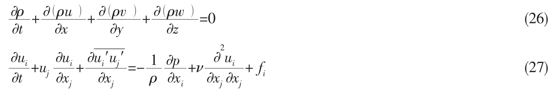
where (u,v,w)is the three components of the velocity of flow along three axes of the cartesian coordinate system, (ρ,p,fi,t,ν,ui,ui′,)is respectively fluid density,fluid static pressure,mass force,time,kinematic coefficient of viscosity,time averaged velocity,fluctuation velocity and Reynolds stress term.
2.2 Turbulence model
Combining the advantages of the Standard K-ε turbulence model and Standard K-ω turbulence model,SST K-ω turbulence model takes the transportation characteristics of the turbulence shear stress into the consideration of turbulence viscous coefficient.SST K-ω turbulence model is able to predict the flow separation area and flow separation points resulted from the adverse pressure gradient.With high applicability and reliability,SST K-ω turbulence model has great advantages in studying and predicting the complex turbulence with flow separation.The transportation equations of its turbulent kinetic energy and turbulent dissipation are as follows[12-13]:

2.3 Three-dimensional RANS method
Solve double-body and free-surface flow models by Reynolds averaged N-S equation,and a method to determine shape factor 1+K and solve hull wave-making resistance by three-dimensional RANS method is put forward:(1)Both the viscous double-body flow and non-viscous double-body flow are numerically solved to obtain the double-body’s corrected total resistance coefficients Ct1,which can be used to calculate the shape factor (1+)K=Ct1/Cf1.where Cf1is the equivalent fraction resistance coefficient obtained based on 1957-ITTC friction resistance coefficient formula.Since there is no free surface,three dimensional RANS method breaks through the limitation of the inflow velocity,unstable flow and wave disturbance,replacing the traditional methods such as Prohaska method and 15th ITTC method in solving the form factor (1+)K;(2)Considering the viscosity and nonlinearity of free surface,the freesurface model flow can be numerically solved to obtain the total resistance Rtand friction resistance Rf;(3)Based on the double-body and free-surface model,ship wave resistance Rwis researched according to three-dimensional resistance division method.
3 Calculation model and meshing
Wigley hull and S60 hull are selected as calculation ship type.Wigley hull is a mathematic hull form,its surface can be expressed by a math equation y=B/2*(1-4x2/L2)*(1-z2/T2).The model parameters for Wigley hull are as follows:L=2.0 m,B/L=0.1,T/L=0.062 5.For S60 hull form,the block coefficient is selected as Cb=0.6,other parameters are L=2.0 m,B=0.267 m,T=0.107 m.
3.1 Meshing based on Rankine source method
The hull surface and free surface are discretized into numbers of surface elements.Rankine source method simulates real wave-making motion through distribution of sources on surface elements.Different meshing numbers can influence calculation results.In theory,free surface is believed to be infinity,but during the process of discretization,only the interfered free surfaces near the hull are taken into consideration.Wave-making has little influence on the further away upstream of free-surface,and the fluctuation of downstream and two sides of the free surface decrease gradually,therefore,the size of free surface is supposed to be selected reasonably to avoid unexpected influence on wave-making flow field.And the size is supposed to be selected according to principal parameters of hull,by reference to meshing experience of Rankine source method,in this paper,the half breadth of free surface is 0.75L,the length of upstream is 0.5L,the length of downstream is 1.5L,meshes at bow and stern are encrypted.Half hull surface of Wigley hull is meshed as 20*8 surface elements,and that of S60 hull is 20*6 surface elements,for both hulls,meshing of free surface is the same,which is 50*16 surface elements.Meshing of hull and free surface are shown in Fig.2 and Fig.3.
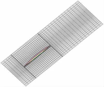
Fig.2 Meshing of Wigley hull
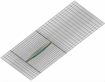
Fig.3 Meshing of S60 hull
3.2 Selection of computational domain
The hull is symmetrical,sails straightly,and the force is symmetrical,so the hull model is half of the ship.Since the ship length and incoming flow velocity for both Wigley hull and S60 hull are the same,the computational domain is also taken as the same.The visualized software Auto CAD and grid generation software ICEM are used to create the calculation model of double-body flow and free-surface flow.Except that the calculation model of double-body does not take the part above the still water surface into consideration,other information is the same with the calculation model of free-surface.
This paper focuses on the selection of computational domain of free surface model.Based on the wave theory,the size of the cubic computational domain for the calculation model of free-surface flow is selected according to the relationship of wave height,wavelength and velocity.The height of computation domain,above water plane,is greater than the maximum height of the ship wave which is determined by ZA=v2/2g,and the wavelength can be obtained based on λw=2πc2/g[16].Since the existence of free surface,the wave surface upheaves at bow.The length of the upstream part is taken bigger than λw.Pressure outlet has been adopted to improve the efficiency and stability of the process of numerical calculation.Taking the effect of fore and aft wave system into consideration,the length of the downstream part is big enough to ensure the flow filed develop fully.The length of the downstream part is 12 m,which is more than eight times of the maximum ship wave length.According to the Kelvin wave system,the reflection of the width of the zone boundary should be reduced as much as possible,and suitable width is determined by the length of computing domain and Kelvin angle.In addition,the influence of the ship wave on the flow field is trivial,when the water depth is larger than λw.The calculation domain partition is shown in Tab.2.
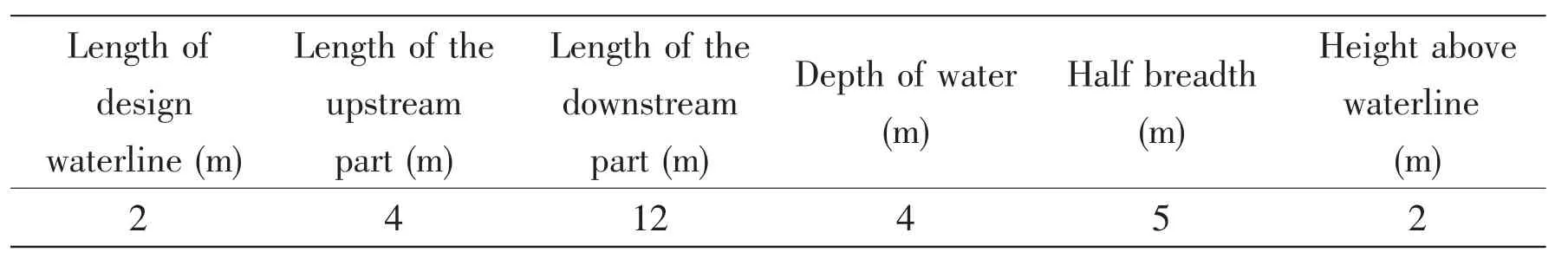
Tab.2 Size of computational domain
3.3 Mesh generation and boundary conditions
Since the existence of the wave-making resistance for free surface model,the mesh near the water plane needs to be refined to track the actual wave profile.The height of the innermost mesh at the level of waterline is taken as 0.005L,and the mesh ratio is set as 1.1.In addition,considering the complexity of the three-dimensional hull surface,the technique of grid encryption has been processed in the bow and stern of the ship.The size of grid is 0.006L.The maximum size of hull surface grid is 0.01L.Boundary layer is needed in the vicinity to the hull surface.The height of the innermost mesh is taken as 1 mm.There are in total 8 layers of mesh in the boundary layer,with a ratio of 1.1.The computational domain are divided into two parts and the hybrid mesh are adopted to perform the numerical calculation.The unstructured mesh is applied to the inner domain with a ratio of 1.1 and the structured mesh is applied to the outer domain with a ratio of 1.3.The interface for structured mesh and unstructured mesh is treated using ICEM software to realize the mesh reconstruction.By this way,the efficiency of data exchange between two kinds of mesh can be significantly increased and the calculation time can be reduced.And there is no free surface,the mesh for the doublebody flow need not consider the part above the still water surface.The model of Wigley hull and S60 hull are shown as Fig.4 to Fig.5.Besides,to maintain high consistency between numerical simulation and EFD method,the boundary conditions for the computational domain are set as Fig.6 to Fig.7.

Fig.4 Model of Wigley hull

Fig.5 Model of S60 hull
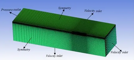
Fig.6 Mesh information of the double-body flow
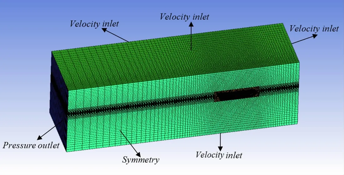
Fig.7 Mesh information of free surface flow
4 Numerical results
4.1 Numerical results for Wigley hull
According to the numerical results of three-dimensional RANS method and Ranking source method,curves of shape factor (1+K)and resistance coefficient are drawn in Fig.8.There is no free surface influence for the shape factor (1+K)obtained by three-dimensional RANS method,and it is not limited by speed,unsteady flow and wave disturbance.The result is related to Froude number,the values of 1+K at different Froude numbers are basically the same,with slight deviation.In Fig.8(b),the friction resistance coefficient decreases with the increase of Reynolds number,the numerical results show agreement with the friction resistance coefficient results calculated based on 1957-ITTC formula.In Fig.8(c),wave-making resistance coefficients of three-dimensional RANS method and Rankine source method match well with experiment data,numerical accuracy requirement is satisfied.And three-dimensional RANS method is of higher accuracy than the Rankine source method because of the consideration of viscosity and nonlinearity of free surface.The numerical results of total resistance coefficient match well with experimental data,and the deviation is small.Numerical results are shown in Fig.8(d).The experimental results of Wigley hull come from ship model test in the towing tank of Osaka University[14].
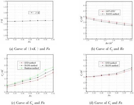
Fig.8 Curves of(1+K),Cf,Cw,Ctand Fn,Re
Tecplot is applied to deal with numerical results of three-dimensional RANS method of Wigley hull and obtain free surface wave profile on the side of ship.And the wave profile on the side of ship with Froude number at 0.25 and 0.3 is compared with that of Rankine source method and EFD method.It is learned from Fig.9 that obtained wave profile of three methods is almost the same,free surface wave crest at side move backward as the Froude number increases.Numerical wave profile of three-dimensional RANS method at most wave height points is better than those of Rankine source method,which is consistent with experimental results.And the values of wave crest on the bow and sides are bigger than that of Rankine source method,while the values of wave trough are opposite.For the first wave crest at bow,the wave height of three-dimensional RANS method which is slightly larger,is very close to experiment result,while the wave height of Rankine source method is smaller than experiment result obviously.The reason for this is that the wave height for Rankine source method is the wave height near the hull instead of the actual wave height on the hull surface,and the Rankine source method does not take the viscosity of water and the nonlinear term of free surface boundary condition into consideration.The experimental results in Fig.9 come from Isikawaji-ma-Harima Heavy Industries Co.,Ltd(IHHI)[10].
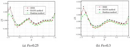
Fig.9 Wave profile for Wigley hull at different Fn
4.2 Numerical results for S60 hull
According to numerical results of S60 hull,curves of shape factor (1+K)and resistance coefficient are drawn in Fig.10,where the values of 1+K at different Froude numbers are different slightly,friction resistance coefficient matches well with 1957-ITTC friction resistance coefficient,with small deviation.And wave-making resistance coefficient of three-dimensional RANS method is of higher numerical accuracy than that of Rankine source method.S60 hull has the same conclusion with Wigley hull,which proves the accuracy and reliability of this method to research wave-making problems.The experimental data of S60 hull come from Ishikawajima-Harima Heavy Industries Co.,Ltd(IHHI)[10].
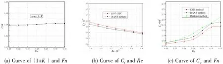
Fig.10 Curves of(1+)K,Cf,Cwand Fn,Re
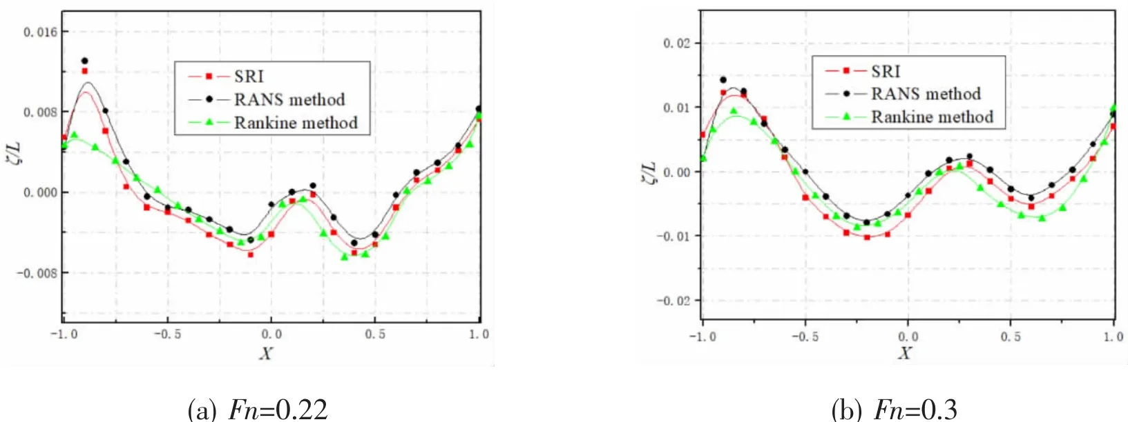
Fig.11 Wave profile for S60 hull at different Fn
Numerical results of three-dimensional RANS method at Fn=0.22 and 0.3 are dealt with Tecplot to obtain wave profile on ship side,as shown in Fig.11,where wave profile is almost the same for three methods.Numerical profile of three-dimensional RANS method at most wave height points is better than that of Rankine source method,its wave crest values at bow and ship side are also bigger,and wave trough values are the opposite.There is a bigger deviation of wave crest value at bow for Rankine source method,the numerical conclusion and cause of deviation of S60 hull are the same with Wigley hull’s.The experimental results in Fig.11 come from Ship Research Institute(SRI)[15](see Takeshi et al,1987).
4.3 Analysis of wave profile
Free surface wave profiles of three-dimensional RANS method and Rankine source method are analyzed numerically to research wave-making characteristics and changing tendency.Numerical results of Wigley hull and S60 hull at Fn=0.24 and Fn=0.3 are dealt with Tecplot to obtain figures of three-dimensional free surface wave profile and contours of wave height.Three-dimensional free surface wave profile is shown in Fig.12 and Fig.13,where wave-making disturbance is obvious at bow,stern and ship sides,and as the Froude number increases,disturbed area enlarges and wave-making region spread outwards,at the same time,Kelvin wave is obvious at fore and aft shoulder of hull,and wave crest moves backwards.The wave profile tends to be coincident for three-dimensional RANS method and Rankine source method,which conforms to the characteristics of Kelvin wave system and is practicable in engineering.
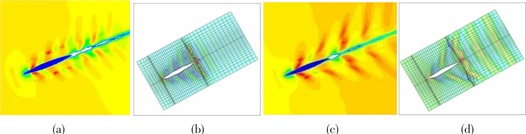
Fig.12 Wave profile of the Wigley hull at various speed(a)Wave profile based on three dimensional RANS method at Fn=0.24;(b)Wave profile based on Rankine source method at Fn=0.24;(c)Wave profile based on three dimensional RANS method at Fn=0.3;(d)Wave profile based on Rankine source method at Fn=0.3
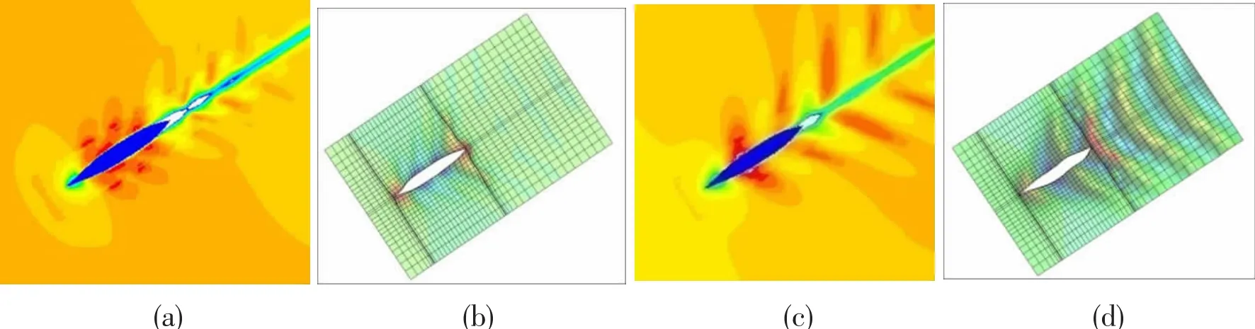
Fig.13 Wave profile of the S60 hull at various speed(a)Wave profile based on three dimensional RANS method at Fn=0.24;(b)Wave profile based on Rankine source method at Fn=0.24;(c)Wave profile based on three dimensional RANS method at Fn=0.3;(d)Wave profile based on Rankine source method at Fn=0.3
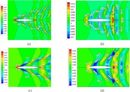
Fig.14 Contours of wave height of the Wigley hull at various speed(a)Contours of wave height based on three dimensional RANS method at Fn=0.24;(b)Contours of wave height based on Rankine source method at Fn=0.24;(c)Contours of wave height based on three dimensional RANS method at Fn=0.3;(d)Contours of wave height based on Rankine source method at Fn=0.3
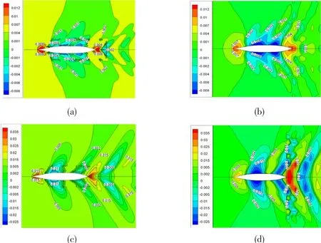
Fig.15 Contours of wave height of the S60 hull at various speed(a)Contours of wave height based on three dimensional RANS method at Fn=0.24;(b)Contours of wave height based on Rankine source method at Fn=0.24;(c)Contours of wave height based on three dimensional RANS method at Fn=0.3;(d)Contours of wave height based on Rankine source method at Fn=0.3
In Fig.14 and Fig.15 of wave height contours,for three-dimensional RANS method and Rankine source method,wave profile changing tendency is almost the same,and there is a slight difference in values of wave profile.At bow and stern,wave crest value of three-dimensional RANS method is bigger than that of Rankine source method,the situation is the opposite for wave trough value,which is consistent with Fig.9 and Fig.11 of wave profile at ship side.Wave crests at bow and stern are very obvious,as the increase of Froude number,wave crest and trough values increase,and coverage area enlarges,besides,wave-making disturbance region at stern and the middle of ship increase,Kelvin wave system can be observed obviously,wave crest moves backwards,which proves numerical results of three-dimensional free surface wave profile figure.
5 Conclusions
This paper applied RANS method and Rankine source method to research wave-making resistance of hull,besides,according to three dimensional resistance division way,a threedimensional RANS method is proposed to solve wave-making resistance.By calculations of viscous double-body flow,non-viscous double-body flow and viscous free-surface flow,and comparisons of wave-making profile,conclusions are reached as follows:
(1)Obtained wave-making resistance by Rankine source method agrees well with results of three dimensional RANS method and EFD method,which proves accuracy of this developed numerical program.
(2)Obtained shape factor based on double-body flow is not influenced by free surface,therefore this method breaks through the limitation of the inflow velocity,unstable flow and wave disturbance.The 1+K can be achieved in a wider range of velocities,and the values of 1+K at different Froude numbers are different slightly.
(3)Wave-making resistance of hull is calculated by three-dimensional RANS method,with the consideration of viscosity,nonlinearity of free surface and complexed three dimensional surfaces of hull.The results conform to that of Rankine source method and EFD method,besides,three dimensional RANS method has higher accuracy than Rankine source method,which proves this numerical method accurate.
(4)Free surface wave profile reflects wave-making characteristics.Wave crest value of free surface by three-dimensional RANS method is bigger than that by Rankine source method,and wave trough value is the opposite.Free surface wave height at bow and stern increases as the increase of Froude number,Kelvin wave system is obvious at fore and aft shoulder of hull,and wave crest moves backwards,wave-making region at midship and stern spreads outwards.The changing tendency is the same with that of Rankine source method.It is turned out that three-dimensional RANS method is practical in engineering.
杂志排行

船舶力学的其它文章
- Mathematical Representation of a 3-D Translating Source Green Function and its Fast Integration Method
- Measures to Restrain Propeller-Hull Vortex Cavitation and Some Discussions
- Evaluation of Turbulence Models for the Numerical Prediction of Time-dependent Cavitating Flow During Water Entry of a Semi-closed Cylinder
- Investigation on Higher-Order Responses of Vortex-Induced Vibration for a Mounted Cylinder
- Dynamic Property and Motion Simulation of Atmospheric Diving Suit
- Experimental Study on Dwell-fatigue of Titanium Alloy Ti-6AL-4V for Offshore Structures