Numerical simulations of 2-D floating body driven by regular waves*
2016-12-06XuebinCHEN陈学彬JieminZHAN詹杰民QinCHEN
Xue-bin CHEN (陈学彬), Jie-min ZHAN (詹杰民), Qin CHEN
1. Department of Applied Mechanics and Engineering, Sun Yat-sen University, Guangzhou 510275, China,
2. Department of Civil and Environmental Engineering, Center for Computation and Technology, Louisiana State University, Baton Rouge, LA, USA
E-mail: 734446371@qq.com
Numerical simulations of 2-D floating body driven by regular waves*
Xue-bin CHEN (陈学彬)1, Jie-min ZHAN (詹杰民)1, Qin CHEN2
1. Department of Applied Mechanics and Engineering, Sun Yat-sen University, Guangzhou 510275, China,
2. Department of Civil and Environmental Engineering, Center for Computation and Technology, Louisiana State University, Baton Rouge, LA, USA
An improved meshing method based on Fluent is used to update the computational meshes in solving the Navier-Stokes(N-S) equations for viscous and incompressible free surface flows with the volume of fluid (VOF) method. To maintain the mesh quality when updating meshes for a moving structure, the computational domain is separated into several parts and each part corresponds to a specific type of body motion. The numerical results of the interaction between the floating body and the regular waves agree well with the experimental data. A total of eight typical motion types are simulated separately to understand the correlation between the motion types and the wave transmission as well as the forces acting on the floating body. Numerical experiments show that the wave transmission increases in the case of sway and heave motions and decreases in the case of pitch motion as compared with the stationary case. It is also found that the sway motion reduces the horizontal wave force acting on the floating body, while the heave motion enhances the vertical wave force.
improved meshing method, wave-structure interaction, sway motion, heave motion, pitch motion
Introduction
Various types of floating structures, such as the floating production, storage, and offloading (FPSO)system, the spar platforms and the floating breakwaters,are widely used in coastal and ocean engineering. The effectiveness and the safety of those structures are closely related with the impact of ocean waves. For the safe operation of such structures, the knowledge of their responses to waves is imperative. But an accurate response analysis is often difficult to make because the structure positions and the water surface are unknown beforehand and the motions of the structure and the waves are nonlinearly coupled. It is therefore important to develop efficient and accurate numerical models to simulate the response of floating structures to ocean waves and understand the physical nature of the interaction between water waves and floating bodies.
Two types of numerical models were used in the literature to simulate the interaction of waves and floating structures. The first one is based on the potential theory, assuming that the flow is irrotational, and the other is based on the Navier-Stokes (N-S) equations for real fluids. For brevity, the first type of models is called the fully nonlinear potential theory (FNPT)model[1]and the second is called the N-S model. FNPT models were employed for problems associated with nonlinear water waves and their interaction with structures. Early FNPT models were primarily formulated in the frequency domain, where the motions of the floating bodies were usually assumed to be small and harmonic in time. The FNPT models in the frequency domain gave satisfactory results with low computational cost, but they may not be applicable to nonlinear transient motion problems, which are often accompanied with a fierce body-wave interaction. Over the past decades, FNPT models in the time domain have gradually replaced the traditional frequency domain method. Bai and Taylor[2]and Ferrant et al.[3]used the time domain method to solve wave diffraction problems and obtained some meaningful results. Based onthe potential flow theory, Guerber et al.[4]proposed a fully nonlinear implicit model for wave interactions with submerged structures in forced and free motions by using the boundary element method. Xue et al.[5]used the high order boundary element method with a mixed Eulerian-Lagrangian time updating to investigate wave-body interactions. However, all FNPT models may break down once an extreme deformation of the free surface occurs, e.g., the reentry of the jet of a breaking wave. Though N-S models may require more computational resources, they are gaining popularity with the rapid development of computing technologies. Hu et al.[6]applied a method based on the constrained interpolation profile (CIP) scheme for handling extremely nonlinear phenomena such as green water impinging on the deck of an advancing ship in waves. Zhang and Zhang[7]used the Reynoldsaveraged Navier-Stokes (RANS) model to simulate the hull/propeller interaction of submarine in submergence and near surface conditions. Zhan et al.[8]studied different turbulence models in the simulation of wave propagations over underwater bodies. Hu and Kashiwagi[9], Sueyoshi et al.[10]and Zhao and Hu[11]investigated the fierce interactions between waves and a 2-D floating body and good results were obtained as compared with experimental data.
The N-S models face a difficulty of the treatment of the varying positions of the structure during each cycle of movement under the wave action. Therefore,the updating of computational meshes around the moving boundary of a floating structure is very important. Mittal and Kumar[12]set a square box of a mesh around the structure, with the box moving together with the structure. For the computational domain outside the box, the meshes were fixed. Therefore, the meshes close to the structure does not undergo any deformation and kept a good quality, to ensure the accuracy of the solution by preserving the gradients in the boundary layers. The motion of the structure is accounted for by adjusting the nodes at the boundaries of the box. The mesh update method used in FLUENT is similar to the idea of Mittal and Kumar[12], and has been demonstrated useful in simulating the wave-structure interaction problems with one degree of freedom[13]. However, this method has difficulties in dealing with problems of multiple degrees of freedom and needs to be improved. The objective of this study is to extend the meshing method proposed by Han et al.[13]to three degrees of freedom and utilize this improved mesh update method to investigate the responses of a floating 2-D body to regular waves. The paper is organized as follows. The next section introduces the numerical model and describes the mesh update method used in this paper. After that, two sets of physical experiments in the literature are used to validate the numerical model. Then numerical simulations are carried out and the correlations between motion types of the floating structure and the wave transmission as well as the wave forces acting on the floating body are discussed. The final section summarizes the findings with several conclusions.
1. Methods
The CFD package, FLUENT, has been successfully utilized to solve the fluid-solid interaction[14-17], and it is used as a basic solver with incorporated C programming language in this paper. To ensure accurate simulated results, we adopt the following basic settings in FLUENT. The pressure staggering option (PRESTO)discretization scheme is used to solve the pressure. The quadratic upwind interpolation of convective kinematics (QUICK) algorithm is used to discretize the momentum and the pressure implicit with splitting of operators (PISO) algorithm is used for the pressurevelocity coupling. The volume of fluid (VOF) method is adopted to capture the fluctuating water surface. The laminar model is used to simulate the flow of the incompressible, viscous fluid.
To deal with the wave-body interaction in the numerical wave flume, the paper incorporates the C programming language into the basic solver through user define function (UDF). The UDF is used to deal with the wave boundary conditions in the inlet, the wave absorbing zone in the rear of the wave flume,the floating body motion and the motion of mesh around the floating body. The wave absorbing method is used by adding a momentum dissipation source term to the momentum equations and the role played by the source terms is similar to the porous structures or the vegetation in the coastal areas. Details about the wave absorbing method can be found in the literature[8,13]. The boundary condition and the meshing method are described as follows.
The incident regular waves are specified by the Stokes wave theory. The free surface elevation and the velocity of second-order Stokes waves are expressed as:
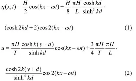
where η is the surface elevation, u and v are the x velocity and y velocity, respectively. H is the wave height, t is the time, ω is the wave angular frequency, k is the wave number (equal to 2Lπ), L is the wave length, d is the water depth, and y is the vertical distance (positive upward)from the still water level.
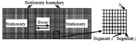
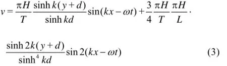
Fig.1 Schematic diagram of the traditional mesh update method in sway motion. The domain is divided into three zones by stationary interfaces, i.e., left zone, right zone and middle zone. Left and right zones keep stationary, while middle zone is subject to sway motion
In FLUENT, a dynamic meshing method similar to the idea of Mittal and Kumar[12]is often utilized to update the computational mesh in every time step. Figure 1 shows the traditional mesh update method[13]in the sway motion. The middle area is the moving zone, while the remaining areas are stationary zones. The moving and stationary zones are separated by two fixed vertical planes. All meshes inside the moving zone move with the same horizontal velocity in every time step. At the same time, the meshes inside the moving zone adjacent to its boundaries are split or merged based on the height of the cells in every time step, which is served as an efficient option in Fluent. These meshes are updated according to the following equations:
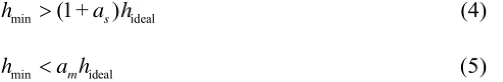
where hminis the minimum cell height of cell layer,hidealis the ideal cell height, and asis the layer split factor,ma is the layer collapse factor. When the condition in Eq.(4) is met, the cells are split based on the specified layering option. This option can be heightbased or ratio-based. When the condition in Eq.(5) is met, the compressed layer of cells is merged into the layer of cells above the compressed layer, i.e., the cells in layer j are merged with those in layer i.
The traditional mesh update method is effective when the moving structure has a single degree of freedom. However, it will encounter difficulties when the structure has multiple degrees of freedom. Fluent itself provides another option of a simple method to handle the multi-degree motion, i.e., the floating body is directly put into a unstructured mesh domain. As the body moves, the unstructured meshes around the body deform, which often leads to excessive distortion of the meshes in a fierce motion. What is more, the mesh around the body can not remain the same high quality in multiple wave cycles, thus reducing the accuracy of body motion under a long duration of wave action.
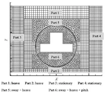
Fig.2 Schematic diagram of the improved mesh update method. The domain is divided into six parts by stationary interfaces and each part is independently designed for a motion type or several motion types, as illustrated in detail on the right of the figure
So far, Fluent itself has not provided a high efficient option to deal with the multi-degree motion without using the secondary developments. To deal with this problem, special treatments have to be made. The UDF is used to model the motion of the floating body in the present study. By incorporating the UDF into the basic solver, we can control the motion types of each mesh component and preserve the mesh quality during the entire computation. The schematic diagram of the improved mesh update method for the motion of an unstrained 2-D moving structure is shown in Fig.2. To retain a good mesh quality when the mesh updates in every time step, the computational zone is separated into 6 small parts by interfaces and each part is designed for a particular motion type or several motion types. Part 6 moves together with the movingstructure, so it is free to heave, sway and pitch. Thus,the meshes close to the structure will not undergo any deformation, and keep a good quality, to ensure the accuracy of the numerical solution. Part 5 also moves together with the moving structure, and it is free to heave and sway, while the pitch motion is prohibited. Part 1 and Part 2 are only allowed to heave and Part 3 and Part 4 keep stationary at all time. Figure 3 shows the mesh distribution in the total domain at two moments when the structure moves, indicating that the method maintains a fine grid and the excessive distortion of the meshes is avoided. The six mesh parts are implemented in the UDF and incorporated into the flow solver of Fluent.
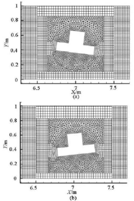
Fig.3 Mesh distribution in the total domain at two moments. The centroid coordinates and pith angle of the body change obviously at two moments, and every part of the mesh domain is in an independent movement and the mesh keeps a good quality all the time
As a separate note, the mesh distribution resolution in Figs.2 and 3 is reduced so that the mesh updating in every time step is clearly presented. Nonetheless, the mesh grid density at the interface of two parts can affect the accuracy of the simulated results. According to the author's convergence tests, the mesh resolutions in the numerical model are: dt=H/40, H/ 15 and H/10 for the near water zone, the deep water zone, and the air zone, respectively, dx=λ/100, b/ 50 and λ/250 for the wave inlet zone, the computation zone around the floating body and the field far from the computation zone. The time step is set as dt=T/1000. H is the incident wave height, λ is the incident wavelength, b is the bottom width of the floating body in x direction and T is the incident wave period.
2. Experimental validation
The available laboratory tests[9-11]are adopted to validate the improved meshing method. The schematic diagram of the numerical set-up and the motion types of the floating body are shown in Figs.4 and 5, respectively. As seen in Fig.5, the floating body is free to heave and pitch, while the sway motion is restrained by two springs. Two experimental cases with different degrees of freedom of the floating body are used to validate the numerical model for the wave-body interactions. These two experimental cases all concern the interaction between the nonlinear wave and the body in shallow water, the incident wave steepnesses (wave height/wavelength) are 0.042 and 0.052, respectively,and the relative water depths (water depth/wavelength)are both 0.27.
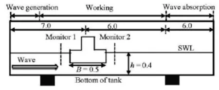
Fig.4 Schematic diagram of numerical setup. The domain is composed of wave generation zone, working zone and wave absorbing zone with the floating body placed at a water depth of =0.4mh. The incident wave propagates from left to right with a specified wave height
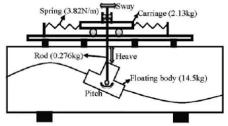
Fig.5 Schematic diagram of motion types of floating body (adapted from Zhao and Hu[11]). The floating body and the device are connected through a vertical rod and the sway motion is restrained by two springs with the same spring constant k = 3.82 N/m , while the heave and pitch motions are free
2.1Body motion with two degrees of freedom-Experiment I
The body motion with two degrees of freedomwithout the sway motion is simulated using the numerical model described above. The wave amplitude is A =0.031m and the wave period is T=1s. In Fig.6(a), a snap shot of the computed velocity field around the floating body is shown. The vortex shedding can be seen in the velocity field at the bottom of the floating body. The pressure field around the floating body is shown in Fig.6(b), where the pressure field does not strictly follow the static pressure distribution at this moment. In Fig.7, the predicted body motions are presented and compared with the experimental results as well as those from the simulated results of Zhao and Hu[11]with the constrained interpolation profile (CIP)-based Cartesian grid method. The computed and measured free surface profiles obtained at =5.1mx in front of the body are also presented for validation. In all experiments, the surface profile data are not available in the rear of the body,so only the surface profiles in front of the body are presented for comparison.

Fig.6 Snap shots of velocity and pressure fields around floating body
It is seen in Fig.7 that the computed results obtained from the numerical model agree favorably with the laboratory measurements for the three parameters examined.0y stands for the still water surface elevation. As for the body motion, we can see nonzero values of the average heave and roll motions, caused by a compact mass of water flowing over the deck(green water, heavy wetness). The amplitude of the heave motion is smaller than the wave amplitude and the amplitude of pitch angle is abouto8. Compared with the experimental data, the current model and the CIP-based method both give good predictions in heave and pitch motions. However, it is clearly shown that the current model provides a better result for the surface elevation monitored at =5.1mx than the CIP-based method. The CIP-based method gives a good prediction for the surface elevation until t=12.5s , and thereafter, the deviation between the CIP-based results and experimental data becomes large, while the current model does not have this kind of deviation. The comparison shows that the current model is capable of simulating a long duration of wave-body interaction as the mesh always preserves a good quality in the entire computation as shown in Fig.3.

Fig.7 Comparison of predicted and measured time histories of regular waves
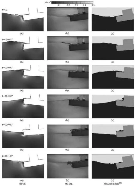
Fig.8 Comparison of free surface and body position between those obtained by different methods and observed experimental data
The simulated green water phenomena are shown in Fig.8 with the photographs taken from the physical experiment as well as the numerical results obtainedby Zhao and Hu[11]. At 0.2T, the water appears on the deck of the floating body and begins to climb up the middle part of the body at about 0.5T. At 0.8T,the green water flows back to the wave tank from the deck. The numerical results include also the velocity distribution around the floating body in Fig.8, which shows that the maximum velocity is around the left corners of the floating body. From the comparison between the results about the free surface and the body position obtained by the current model and those of Zhao and Hu[11], we can see that there is no significant difference, except for the moment at 0.8T, where our model gives a slightly better result than the CIP-based method. Besides, the current model also gives the velocity distribution around the floating body, which shows that there are the water particles around the left corners of the floating body impacting on the body with a large velocity. It is also shown that the small bubbles at the left corner of the floating body are caused by the fierce collision when the green water with the largest velocity flows back to the wave tank from the deck. The green water phenomenon can be recommended for screening the applicability of a model to predict highly nonlinear phenomena like a large amplitude body motion.
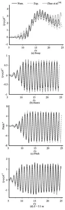
Fig.9 Comparison of predicted and measured body motions due to regular waves with sway motion restrained. The upper left and upper right subfigures are about the sway and heave motions, respectively. The lower left and lower right subfigures are about the pitch motion and surface elevation at =5.1mx, respectively
2.2Body motion with three degrees of freedom-Experiment II
In this experiment, the floating body is free to heave and pitch while the sway motion is restrained by two springs with a spring constant of 3.82 N/m. The wave amplitude A=0.0192mand the period T=1s. Figures 10 shows the predicted body motions and water levels at =5.1mx as compared with the experimental results and the simulated results by Zhao et al.[18]obtained with the CIP-based method.
The left top panel in Fig.9 shows the sway motion. In each wave cycle, the floating body moves forward in the first half period and backward in the second half period under the actions of the wave force and the spring force. In the beginning, with a large wave action,the floating body moves forward and the spring reaction force is increased. At about 16.5 s, the sway distance as well as the spring reaction force reach their maximums and both of the two simulated results agree well with the experimental data. Subsequently, the floating body begins to move backward with decreasing spring force. Then the floating body is pushed forward by the wave force again and a discrepancy appears in the two numerical models as compared with experimental data. The floating body returns to the forward motion at about =21st in the CIP-based method, which is earlier than that (=23s)t predicted by the current model and the experimental results. The deviation between the simulated results obtained by the CIP-based method and the experimental data getslarger and larger after =21st, while the deviation between the simulated results obtained by the current method and the experimental data is much smaller after a long time wave-body interaction. The amplitude of the heave motion is smaller than the wave amplitude, and the CIP-based method predicts a little better results than the current method. Both the CIP-based method and the current method predict accurately the pitch motion and the wave elevation at =x 5.1 m as compared with the experimental data.
In the two validation cases, the small deviation between the simulated results (heave, pitch, sway, x=5.1m ) and the experimental data is seen both for the CIP-based method and the current method. The small deviation might probably be caused by the simplification of the 3-D experimental model to a 2-D numerical model. In the 3-D experiment, a small amount of water could pass the floating body from the gaps between the body and the sidewalls, while the gap does not exist in the 2-D models. As a result, the horizontal wave force is increased and the sway motion is over-predicted in the 2-D model as shown in the first subfigure of Fig.9, thus the heave and pitch motions are also affected. Zhao and Hu[11]also suggested that the deviations were due to the wave reflection. In Experiment I, the results of the current method and the CIP-based method both have small deviations for the heave and pitch motions except the wave elevation in front of the floating body where the CIP-based method has produced a relatively large deviation after a long wave-body interaction time. In Experiment II, the simulated results by the current method and the CIP-based method are both in good agreement with the experimental results. The current method predicts a better result of sway motion than the CIP-based method after a long period of time. In overall, the current method can accurately simulate not only the movement of the floating body, but also the wave field that drives the motion, especially under a long period of time.
3. Regular wave transmission and forces acting on floating body
The wave transmission and the forces on the floating body differ greatly when the floating body has different degrees of freedom driven by regular waves. In order to better understand the correlation between them, we consider different types of motions under the same wave condition. A numerical wave gage is set behind the floating body at =7.8mx to measure the wave transmission.
For the purpose of clarity and simplicity, we define herein the dimensionless amplitude of the horizontal wave force asxF, while the amplitude of the vertical force is denoted byyF. The transient wave forces are obtained by integrating the water pressure throughout the body surface in each time step. The wave force amplitudes, i.e.,xF andyF, are the averaged values of 10 amplitudes in the time series of the transient wave forces. They are both normalized by ρgDHB , where ρ is the water density, g is the gravity acceleration, D is the water depth, H is the incident wave height, and B is the 3-D floating body thickness, which is assumed to be 1 in the current 2-D model. The wave profile is normalized by /2H. Based on the two sets of experiments mentioned above,a total of eight typical motion types are simulated separately. We analyze and discuss the correlation between the motion types and the wave transmission as well as the forces acting on the floating body as follows.
3.1Simulation and discussion based on Experiment I
Based on Experiment I, we consider 4 types of motions (stationary, heave, pitch and heave + pitch)under the same wave condition. Numerical experiments are carried out for the four cases. The computed results about the monitored surface elevation and the forces acted on the floating body are shown in Table 1.
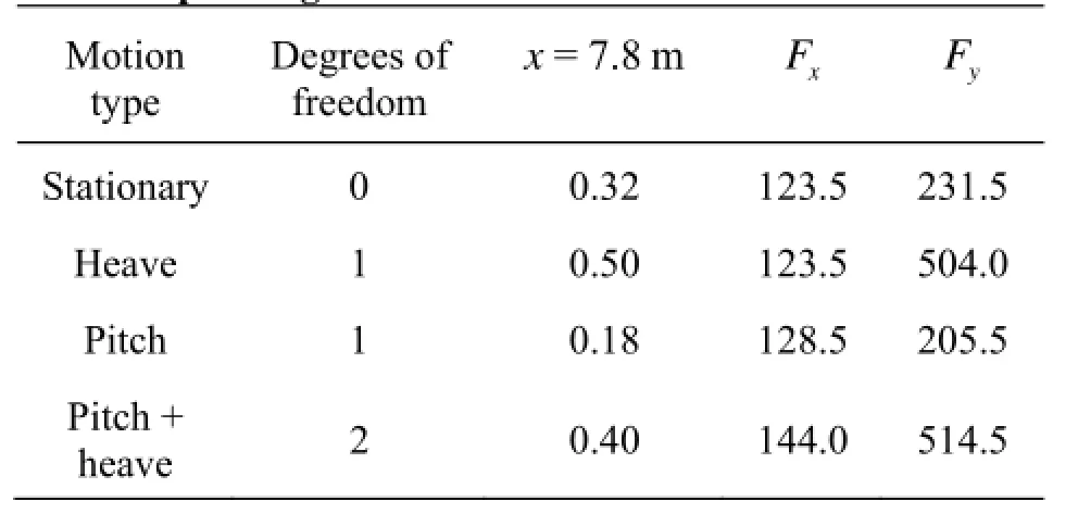
Table 1 Different motion types of the body and the corresponding monitored data and forces
From the simulated surface elevations behind the floating body at x=7.8m , we can see that the wave transmission is also strongly influenced by the floating body's degrees of freedom. Here is an interesting phenomenon. When the floating body is free to heave,the transmitted wave amplitude is the largest, while the transmitted wave amplitude is the smallest when the body is free to pitch. It seems that there is no correlation between the motion types of the body and the wave passing ability, but it is found that the heave motion plays a positive role and the pitch motion plays a negative role in the wave transmission as compared with the stationary case. When the body is free to pitch and heave, the extent of the wave transmission is between the stationary case and the heave case, which suggests that the extent of the positive role of the heave motion is larger than that of the pitch motion. When the movement of the floating body contains the heave,the wave transmission is increased, and when the body motion contains the pitch, the wave transmission is decreased.
For the wave forces, a small change is found in the amplitude of the horizontal forcexF when the body is free to move in different motion types. An interesting phenomenon is seen in the amplitude of the vertical forceyF. When the floating body is free to pitch, the vertical force is the same as that of the stationary case, but when the motion contains the heave,the force amplitude becomes larger. The amplitude of the horizontal forcexF remains almost constant regardless of different motion types, while the amplitude of the vertical forceyF varies.
3.2Simulations and discussions based on Experiment II
Based on Experiment II, we consider 8 types of motions (stationary, heave, sway, pitch, sway + pitch,sway + heave, heave + pitch and heave + sway + pitch)under the same wave condition. Numerical experiments are carried out for the eight cases. The corresponding waves and forces computed by our numerical model are shown in Table 2.

Table 2 Different motion types of the body and the corresponding monitored data and forces
From the simulated surface elevations behind the floating body at =7.8mx, we can see that the wave transmission is also strongly influenced by the floating body's degrees of freedom. When the body is free to heave, the transmitted wave amplitude takes the largest value, while the transmitted wave amplitude takes the smallest value when the body is free to pitch. This phenomenon is the same as that observed in Experiment I, which indicates that the pitch motion could effectively reduce the transmitted wave energy. When the body is free to sway, the transmitted wave amplitude is also large. In overall, the heave and sway motions play a positive role and the pitch motion plays a negative role in the wave transmission as compared with the stationary case. When the motion type is heave + pitch, the transmitted wave amplitude takes a value between the stationary case and the heave case,which suggests that the extent of the positive role of the heave motion is larger than that of the pitch motion. The same phenomenon happens in the sway + pitch case. When the body motion contains heave and sway, the transmitted wave amplitude is increased,while when the body motion contains pitch, the transmitted wave amplitude is decreased.
For the wave forces, the amplitude of the horizontal force Fxdiffers greatly when the body has different motion types. The amplitude of the horizontal force is the largest in the stationary case, which indicates that the horizontal force amplitude is reduced in whatever motion types and it is somewhat different from the phenomenon found in Experiment I. In overall, when the body motion contains sway, the horizontal force decreases. An interesting phenomenon is also found in the amplitude of the vertical force Fy. It is observed that the amplitude of the vertical force Fyremains almost constant in the cases with no heave motion. The table clearly shows that the horizontal force amplitude Fxis reduced when the sway motion type is included and the amplitude of the vertical force Fytakes two obviously different values.
Tables 1 and 2 show the heave motion makes the vertical wave force increase, while other types of motions do not significantly affect the magnitude of the vertical force. Bai and Taylor[19]used the higher-order boundary element method to study the wave interaction with stationary and movable truncated cylinders,and also indicated that the heave motion led to a larger vertical force, while the sway motion almost had no influence on the horizontal force. Table 2 shows that the sway motion reduces the horizontal wave force acting on the floating structure, while other types of motion do not significantly affect the magnitude of the horizontal force. Shao and Gotoh[20]used SPH-LES model to simulate the wave interaction with stationary and movable curtain walls and found that the horizontal hydrodynamic force on the movable curtain wall is reduced significantly as compared with the stationary case. The same phenomenon was also observed by Bai and Taylor[19]on stationary and movable truncated cylinders. It is noted that the heave motion has a much stronger influence onyF than the sway motion onxF in Tables 1 and 2, which might be due to the following reasons. First, the floating body is free to heave in the vertical direction while the sway motionis restrained by springs in the horizontal direction and the effect of the sway motion on the horizontal force is weakened. Second, the buoyancy is the main component ofyF and the immersed water depth of the floating body changes a great deal in the heave motion. Third, the green water phenomenon also makes the influence of the heave motion onyF increase. Last but not least, the 2-D model might have a certain influence onxF andyF as the wave is absolutely blocked by the floating body near the water surface zone in the 2-D model.
Compared with the stationary case, the heave and sway motions both enhance the wave transmission. Similar phenomenon was also found by Shao and Gotoh[20]in the investigation on stationary and movable curtain walls, meaning that the wave deformation is more significant in the stationary wall case and the water surface line is cut off by the stationary curtain wall as compared with the movable case. Koutandos et al.[21]conducted experiments on the wave transmission characteristics of a suspended box-typed floating breakwater in a large-scale facility, and the results revealed that the heave motion increased the wave transmission when the relative platform width (platform width/wavelength) was larger than 0.19 at two different wave heights. The wave transmission test of a box-type floating breakwater connected to the sea bed by mooring chains was later conducted by Dong et al.[22]with two different lengths of the mooring chain, and the results showed a lower degree of tightness of the mooring chain led to a larger wave transmission coefficient, and vice versa. It should be noted that Tables 1 and 2 also mean that not all motion types of the current floating body have a positive contribution to the wave transmission, such as the pitch motion reduces the wave transmission. The blocked area of the floating body is particularly important in the wave transmission, especially, in a 2-D model where the wave diffraction is prohibited. Compared with the stationary case, the blocked area of the floating body in a pitch motion is increased whenever the pitch angle is negative or positive, which affects greatly the wave transmission. Schwimmer[23]suggested that the shoreline erosion was closely correlated with the wave energy near the shoreline. Based on the above findings about the wave transmission of the floating body with different motion types, the floating breakwaters similar to the current model with only pitch motion might be efficient systems for the shoreline protection in the coastal area.
4. Conclusion
In this paper, a numerical model with an improved mesh update technique based on Fluent is employed to simulate the nonlinear interactions between waves and a floating body. First, the model is tested against two laboratory experiments as well as the CIP-based method on the response of a 2-D floating body to regular waves. Good results are obtained as compared with the laboratory measurements, which indicates that the improved mesh update method is suitable for investigating the long time interaction between waves and floating bodies. The validated numerical model is used as a tool to improve the understanding of the wave and floating body interactions. A series of numerical experiments are carried out to determine the correlation between the wave transmission and the type of body motion as well as the wave forces acting on the floating structure. It is found that the heave and sway motions of a floating body enhance the wave transmission while the pitch motion reduces it as compared with the stationary case. The numerical simulations reveal that the sway motion reduces the horizontal wave force acting on the floating body while the heave motion enhances the vertical wave force.
Acknowledgement
References
[1]YAN S., MA Q. W. Numerical simulation of fully nonlinear interaction between steep waves and 2D floating bodies using the QALE-FEM method[J]. Journal of Computational physics, 2007, 221(2): 666-692.
[2]BAI W., TAYLOR R. E. Numerical simulation of fully nonlinear regular and focused wave diffraction around a vertical cylinder using domain decomposition[J]. Applied Ocean Research, 2007, 29(1): 55-71.
[3]FERRANT P., TOUZE D. L. and PELLETIER K. Nonlinear time-domain models for irregular wave diffraction about offshore structures[J]. International Journal for Numerical Methods in Fluids, 2003, 43(10-11): 1257-1277.
[4]GUERBER E., BENOIT M. and GRILLI S. T. et al. A fully nonlinear implicit model for wave interactions with submerged structures in forced or free motion[J]. Engineering Analysis with Boundary Elements, 2012, 36(7): 1151-1163.
[5]XUE M., XU H. and LIU Y. et al. Computations of fully nonlinear three-dimensional wave-wave and wave-body interactions. Part 1. Dynamics of steep three-dimensional waves[J]. Journal of Fluid Mechanics, 2001, 438: 11-39.
[6]HU C., ZDRAVKO K. and KASHIWAGI M. et al. Application of CIP method for strongly nonlinear marine hydrodynamics[J]. Ship Technology Research, 2006, 53(2): 74-87.
[7]ZHANG Nan, ZHANG Sheng-li. Numerical simulation of hull/propeller interaction of submarine in submergence and near surface conditions[J]. Journal of Hydrodynamics, 2014, 26(1): 50-56.
[8]ZHAN J. M., DONG Z. and JIANG W. et al. Numericalsimulation of wave transformation and runup incorporating porous media wave absorber and turbulence models[J]. Ocean Engineering, 2010, 37(14): 1261-1272.
[9]HU C., KASHIWAGI M. Two-dimensional numerical simulation and experiment on strongly nonlinear wavebody interactions[J]. Journal of Marine Science and Technology, 2009, 14(2): 200-213.
[10] SUEYOSHI M., KASHIWAGI M. and NAITO S. Numerical simulation of wave-induced nonlinear motions of a two-dimensional floating body by the moving particle semi-implicit method[J]. Journal of Marine Science and Technology, 2008, 13(2): 85-94.
[11] ZHAO X., HU C. Numerical and experimental study on a 2-D floating body under extreme wave conditions[J]. Applied Ocean Research, 2012, 35(1): 1-13.
[12] MITTAL S., KUMAR V. Flow-induced oscillations of two cylinders in tandem and staggered arrangements[J]. Journal of Fluids and Structures, 2001, 15(5): 717-736.[13] HAN Y., ZHAN J. M. and SU W. et al. Numerical simulation of in-line response of a vertical cylinder in regular waves[J]. Journal of Coastal Research, 2013, 31(4): 879-891.
[14] WANG Hong-zhi, ZOU Zao-jian. Numerical prediction of hydrodynamic forces on a ship passing through a lock[J]. China Ocean Engineering, 2014, 28(3): 421-432.
[15] WANG Hong-zhi, ZOU Zao-jian. Numerical prediction of hydrodynamic forces on a ship passing through a lock with different configurations[J]. Journal of Hydrodynamics, 2014, 26(1): 1-9.
[16] MO Song, HUANG Hai-ming and HUANG guo et al. Numerical simulation of gap effect in supersonic flows[J]. Theoretical and Applied Mechanics Letters, 2014, 4(4): 65-69.
[17] WU Xiao-cui, WANG Yi-wei and HUANG Cheng-guang et al. Experiment and numerical simulation on the characteristics of fluid-structure interactions of non-rigid airships[J]. Theoretical and Applied Mechanics Letters,2015, 5(6): 258-261.
[18] ZHAO X., LU F. and ZHANG Y. et al. A CIP-based simulation of 2-D floating body response to regular waves[C]. 13th National Conference on Modern Mathematics and Mechanics. Shanghai, China, 2012, 1-6(in Chinese).
[19] BAI W., TAYLOR R. E. Fully nonlinear simulation of wave interaction with fixed and floating flared structures[J]. Ocean engineering, 2009, 36(3): 223-236.
[20] SHAO S., GOTOH H. Simulating coupled motion of progressive wave and floating curtain wall by SPH-LES model[J]. Coastal Engineering Journal, 2004, 46(2): 171-202.
[21] KOUTANDOS E., PRINOS P. and GIRONELLA X. Floating breakwaters under regular and irregular wave forcing: Reflection and transmission characteristics[J]. Journal of Hydraulic Research, 2005, 43(2): 174-188.
[22] DONG G. H., ZHENG Y. N. and Li Y. C. et al. Experiments on wave transmission coefficients of floating breakwaters[J]. Ocean Engineering, 2008, 35(8): 931-938.
[23] SCHWIMMER R. A. Rates and processes of marsh shoreline erosion in Rehoboth Bay, Delaware, USA[J]. Journal of Coastal Research, 2001, 17(3): 672-683.
E-mail: 734446371@qq.com
(September 25, 2015, Revised August 3, 2016)
* Project supported by the National Marine Public Welfare Research Project of China (Grant No. 201005002).
Biography: Xue-bin CHEN (1989-), Male, Ph. D.
Jie-min ZHAN,
E-mail: cejmzhan@vip.163.com
The gratefully acknowledges the assistance provided by Li Tian-zeng in writing this paper.
杂志排行

水动力学研究与进展 B辑的其它文章
- Sharp interface direct forcing immersed boundary methods:A summary of some algorithms and applications*
- On the modeling of viscous incompressible flows with smoothed particle hydrodynamics*
- Flow characteristics of the wind-driven current with submerged and emergent flexible vegetations in shallow lakes*
- Reverse motion characteristics of water-vapor mixture in supercavitating flow around a hydrofoil*
- Study of fluid resonance between two side-by-side floating barges*
- Modelling of a non-buoyant vertical jet in waves and currents*