Numerical Optimization on Aerodynamic/Stealth Characteristics of Airfoil Based on CFD/CEM Coupling Method
2016-09-05JiangXiangwenZhaoQijunZhaoGuoqingMengChen
Jiang Xiangwen, Zhao Qijun, Zhao Guoqing, Meng Chen
National Key Laboratory of Science and Technology on Rotorcraft Aeromechanics,Nanjing University of Aeronautics and Astronautics,Nanjing 210016,P.R.China
(Received 16 May 2015; revised 18 July 2015; accepted 25 July 2015)
Numerical Optimization on Aerodynamic/Stealth Characteristics of Airfoil Based on CFD/CEM Coupling Method
Jiang Xiangwen, Zhao Qijun*, Zhao Guoqing, Meng Chen
National Key Laboratory of Science and Technology on Rotorcraft Aeromechanics,Nanjing University of Aeronautics and Astronautics,Nanjing 210016,P.R.China
(Received 16 May 2015; revised 18 July 2015; accepted 25 July 2015)
Based on computational fluid dynamics (CFD)/computational electromagnetics method (CEM) coupling method and surrogate model optimization techniques, an integration design method about aerodynamic/stealth characteristics of airfoil is established. The O-type body-fitted and orthogonal grid around airfoil is first generated by using the Poisson equations, in which the points per wave and the normal range satisfy the aerodynamic and electromagnetic calculation accuracy requirement. Then the aerodynamic performance of airfoil is calculated by solving the Navier-Stokes (N-S) equations with Baldwin-Lomax (B-L) turbulence model. The stealth characteristics of airfoil are simulated by using finite volume time domain (FVTD) method based on the Maxwell′s equations, Steger-Warming flux splitting and the third-order MUSCL scheme. In addition, based upon the surrogate model optimization technique with full factorial design (FFD) and radial basis function (RBF), an integration design about aerodynamic/stealth characteristics of rotor airfoil is conducted by employing the CFD/CEM coupling method. The aerodynamic/stealth characteristics of NACA series airfoils with different maximum thickness and camber combinations are discussed. Finally, by choosing suitable lift-to-drag ratio and radar cross section (RCS) amplitudes of rotor airfoil in four important scattering regions as the objective function and constraint, the compromised airfoil with high lift-to-drag ratio and low scattering characteristics is designed via systemic and comprehensive analyses.
rotor airfoil; aerodynamic characteristics; stealth characteristics; CFD/CEM coupling; surrogate model
0 Introduction
The selection of rotor airfoil not only affects aerodynamic characteristics of the helicopter directly, but also is the key to reduce radar cross section (RCS) characteristics of the armed helicopter rotor. Currently, the integrated optimization analyses about aerodynamic and stealth design of advanced helicopter rotor are an important trend. Therefore the integrated analyses about aerodynamic and stealth characteristics of rotor airfoil are a challenging multidisciplinary design optimization (MDO) issue.
With the great improvements in computational fluid dynamics (CFD) method, computational electromagnetics method (CEM) and optimization algorithms, integrated analyses about aerodynamic/stealth characteristics of airfoil are becoming more and more feasible in modern MDO rotor design. The CFD technology has been widely used in rotor airfoil aerodynamic analyses and designs during the past decade[1]. Based on CFD technology, the finite volume time domain (FVTD) method was established for solving radar scattering problem. The FVTD method was first applied to calculate electromagnetic characteristics of targets by Shankar[2]in the 1980s, Camberos[3]developed COBRA software by Steger-Warming flux discretization combined with the four-stage Runge-Kutta time scheme, which can handle some simple targets. In recent years, high precision FVTD method has been preliminarily used in some complex targets[4-5]. In the integrated investigation of airfoil, Hoang Vinh[6]and Zhu[7]coupled CFD ( full-potential or Euler equations) with CEM method to conduct the preliminary MDO of airfoil.
At present, some integrated research of wing airfoil mainly focuses on calculating its aerodynamic characteristics with reduced order models, and then find the optimal airfoils with specified constraint condition (RCS of airfoil leading edge) in the optimization methods. The motions of helicopter rotor blade include rotating, pitching and flapping. Therefore the rotor blades work in extraordinary and seriously unsteady environment compared with the fixed-wing aircraft in flight, and the aerodynamic characteristics of rotor airfoil are very complex such as shock waves on the advancing blade tip and separated flow regions at the retreating side. Meanwhile, the electromagnetic scattering characteristics about leading edge, upside, downside and trailing edge are all important for the rotor airfoil. So the integrated analyses about aerodynamic and stealth must take into account four important scattering regions of airfoil, which are conducive to rotor stealth design of armed helicopter.
To develop a high precision computational method that can be used in MDO design of rotor airfoil, an integration design based CFD/CEM coupling method is proposed to predict aerodynamics/stealth characteristics of airfoil in this paper. In order to satisfy practice needs, NACA airfoils which are widely used in aviation are selected as baseline airfoils. The O-type aerodynamic/RCS computational grids are generated by solving Poisson equations. The airfoil aerodynamics/stealth characteristics are simulated by high precision CFD/ FVTD methods. Then an integration design about CFD/CEM coupling method is developed by optimization surrogate model technique. Additionally, the aerodynamic and stealth characteristics of NACA series airfoils with different maximum thickness and camber combinations are discussed. Finally, choosing suitable objective function and constraint condition about lift-to-drag ratio and RCS amplitudes of rotor airfoil at four important scattering regions, the rotor airfoil with high lift-to-drag ratio and low scattering characteristics is designed after comprehensive analyses.
1 Computational Methods
1.1Grid generation techniques
The O-type body-fitted and orthogonal grids around rotor airfoil are generated by using Poisson equations. The grids around airfoil are shown in Fig.1. The aerodynamic/stealth computational grid contains 300×70 points, among which 150 points are on the lower and upper surfaces of the airfoil respectively, and 70 points in the direction normal to the airfoil′s surface. The four important scattering regions of rotor airfoil are leading edge (150°≤ψ≤210°), upside (60°≤ψ≤120°), downside (240°≤ψ≤300°) and trailing edge (-30°≤ψ≤30°), respectively.

Fig.1 Computational grids around NACA0012 airfoil
1.2CFD method
The airfoil flowfield characteristics are calculated by Navier-Stokes (N-S) equations with Baldwin-Lomax (B-L) turbulence model which is based on the previous work[8-9].
The N-S equations in integral form can be written as where x and y are the Cartesian coordinates, U the vector of conserved variables, F, G the inviscid fluxes, and Fv,Gvthe viscous fluxes.
(1)
(2)
where ρ,P and Efare the density, pressure and total energy per unit mass, respectively, k the air heat transmission factor, τ the viscous related items, μf=μlf+μtf. μfis the coefficient of viscosity, μlfand μtfthe laminar flow and turbulent flow coefficient of viscosity respectively.
Spatial discretization is conducted by the central difference scheme, and time discretization is conducted by the four-stage Runge-Kutta method. Boundary conditions are the non-reflection[10]. The viscous effect is calculated by using B-L turbulent model with strong robustness and high reliability, and the turbulent model can effectively simulate the attached flow and medium separation flow.
1.3CEM method
1.3.1Governing equations
Maxwell′s equations in the differential form for wave propagation in free space can be expressed as
(3)
where B is the magnetic induction, E the electric field vector, D the electric field displacement, and H the magnetic field vector. B=μH, μ is the magnetic permeability, and D=εE, ε is the electric permittivity. The above equations are applied to every finite-volume cell in the grid. The integral form can be written as
(4)
1.3.2Discretization of equations
The combination of third-order MUSCL scheme and Steger-Warming[11]flux-vector splitting algorithm were derived to solve Maxwell′s equations in conservative form. The spatial discretized formulation for the cell is
(5)

The four-stage Runge-Kutta method is also used for the temporal discretization.
1.3.3Boundary conditions
For a perfect electrically conducting (PEC) body, the boundary conditions[12]of the electric and magnetic fields are required, respectively, as where superscript ″t″ denotes total of the incident and scattered fields, and n denotes the outward unit normal vector.
(6)
1.3.4RCS evaluation
The frequency-domain field can be transformed from the time-domain electromagnetic field by Fourier transform, and the RCS is solved by near-far field conversion. Radar scattering is calculated as where σ is the radar cross section and R0the distance from scattering object to observation point. Superscript ″i″ denotes the incident field, and superscript ″s″ denotes the scattered field.
(7)
1.4Surrogate model
Surrogate model is developed with experiment design methods and approximation models.
The full factorial design (FFD) has advantages of analyzing interactions among factors and effects of each factor on the system.
Radial basis functions were developed by Hardy[13]which use linear combinations of a symmetric function based on Euclidean distance to establish approximation models. Radial basis function (RBF) approximations fit good to arbitrary contours of both deterministic and stochastic response functions. A simple form of RBF is
(8)

The predictive model should satisfy the following interpolation conditions
(9)
Eq.(8) can be expressed as
(10)

1.5CFD/CEM coupling method
Based upon CFD, FVTD and surrogate model, an integration design about aerodynamic/stealth of rotor airfoil is developed. Fig.2 shows the flow chart of integrated design based on CFD/CEM coupling strategy. The method consists of three modules: grid generation, solvers and integrated design.
1.5.1Grid generation module
Satisfying density and orthogonality of grid by adjusting the source term in the Poisson equations, the airfoil O-type body-fitted and orthogonal grids are generated. The nodes, area and vector of computational grid data are presented by conversion program.
1.5.2Solver modules
Based upon finite volume method and B-L turbulence model, N-S equations are chosen to solve the flowfield and aerodynamics characteristics.
Based upon FVTD method, Maxwell′s equations are chosen to solve the electromagnetics field and RCS characteristics.
1.5.3Integrated design module
An optimization systemic methodology is developed from FFD and RBF. By choosing suitable objective function and constraint condition, an integration design about aerodynamic/stealth of airfoil is conducted. If optimized airfoil that satisfies high lift-to-drag ratio and low scattering characteristics, the method provides airfoil geometric parameters, if not, recalculate.

Fig.2 Flow chart of integrated design based on CFD/CEM coupling strategy
2 Results and Discussion
2.1Test cases
The aerodynamic case: NACA0012 airfoil at Ma=0.7 and Re=9×10⁶. As shown in Fig.3, the calculated lift, pressure distributions and polar curve are in good agreements with the experimental data[14]. It has been demonstrated that the method is effective to simulate the aerodynamic characteristics of rotor airfoil.

Fig.3 Comparisons of numerical and experimental results for aerodynamic characteristics of NACA0012 airfoil
The RCS case: NACA0012 airfoil at TM and TE waves, L=10λ, incident angleφ=90°. As shown in Fig.4, the calculated results are in excellent agreements with the reference data[15]. It suggests that the method is effective in simulating the stealth characteristics of airfoil.
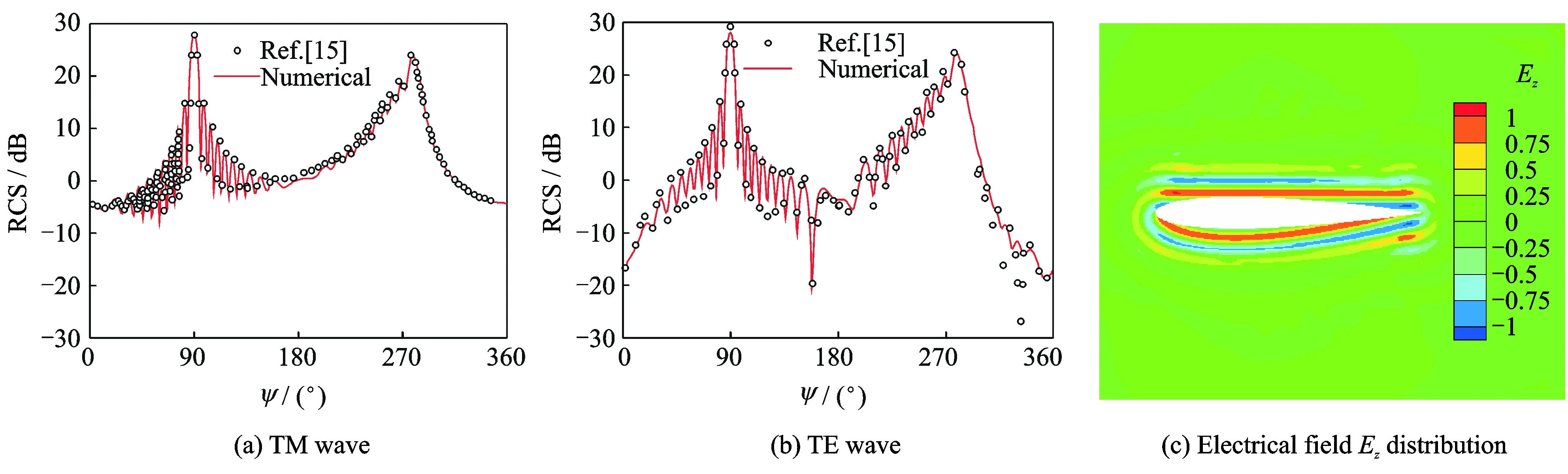
Fig.4 Comparisons of numerical and results for RCS characteristics of NACA0012 airfoil
2.2Aerodynamic and RCS responses of airfoil parameters
The parameters of airfoil are maximum thickness, maximum camber and different maximum thickness and camber combinations. The calculated status:Ma=0.4,Re=9×10⁶, angle of attackα=0°, TM wave, and incident angleφ=0°.
2.2.1Response to maximum thickness
Fig.5 shows aerodynamic and RCS characteristics of NACA airfoils with different maximum thicknesses. The lift coefficient of NACA24 Tmaxchanges relatively flat and the drag coefficient increases rapidly as shown in Fig.5(a), where Tmaxdenotes maximum thickness. The surface pressure coefficient distributions of the three airfoils are compared in Fig.5(b). The upper part distributions of Fig.5(c) depict RCS of five airfoils, and its lower part is the RCS difference of NACA2410 with the other airfoils. With the increase of the airfoil maximum thickness, the curvatures of leading and trailing edge become large, and the distributions of scattering energy are changed. As a result, the scattering fields of leading edge are more and more stronger,and RCS of airfoil trailing edge shows more obvious oscillation.

Fig.5 Aerodynamic and RCS characteristics of NACA series airfoils with different maximum thicknesses
2.2.2Response to maximum camber
Fig.6 shows aerodynamic and RCS characteristics of NACA airfoils with different maximum cambers. The lift and drag coefficients of NACA Cmax412 increase rapidly shown in Fig.6(a), where Cmaxdenotes airfoil maximum camber. The surface pressure coefficient distributions of the three airfoils are shown in Fig.6(b). The upper part distributions of Fig.6(c) depict RCS of the five airfoils, and its lower part is the RCS difference of NACA1412 with the other airfoils. With the increase of the airfoil maximum camber, the curvatures of upside and downside surfaces become small, and the shape of trailing edge is changed significantly. As a result, the RCS amplitudes of upside surface are improved, the RCS amplitudes of downside surface are reduced, and RCS oscillations in other parts are not significant except at the trailing edge of airfoil.

Fig.6 Aerodynamic and RCS characteristics of NACA series airfoils with different maximum cambers
2.2.3Response to combinations of maximum thickness and camber
Fig.7 shows aerodynamic and RCS characteristics of NACA series airfoils with different maximum thickness and camber combinations. For integration design, we hope K (the lift-to-drag ratio) is higher and RCS mean value is lower. As can be seen, the RCS distributions about leading edge, upside, downside and trailing edge of airfoils are different. The airfoil lift-to-drag ratio of upper part in Fig.7 is higher, which is beneficial to the aerodynamic characteristics, but not conducive to reducing RCS. The RCS mean value of lower part in Fig.7 is smaller, which are beneficial to the stealth characteristics, but not conducive to aerodynamic performances. So choosing theoptimal airfoil with high aerodynamic performance and low scattering characteristics is a compromised process.
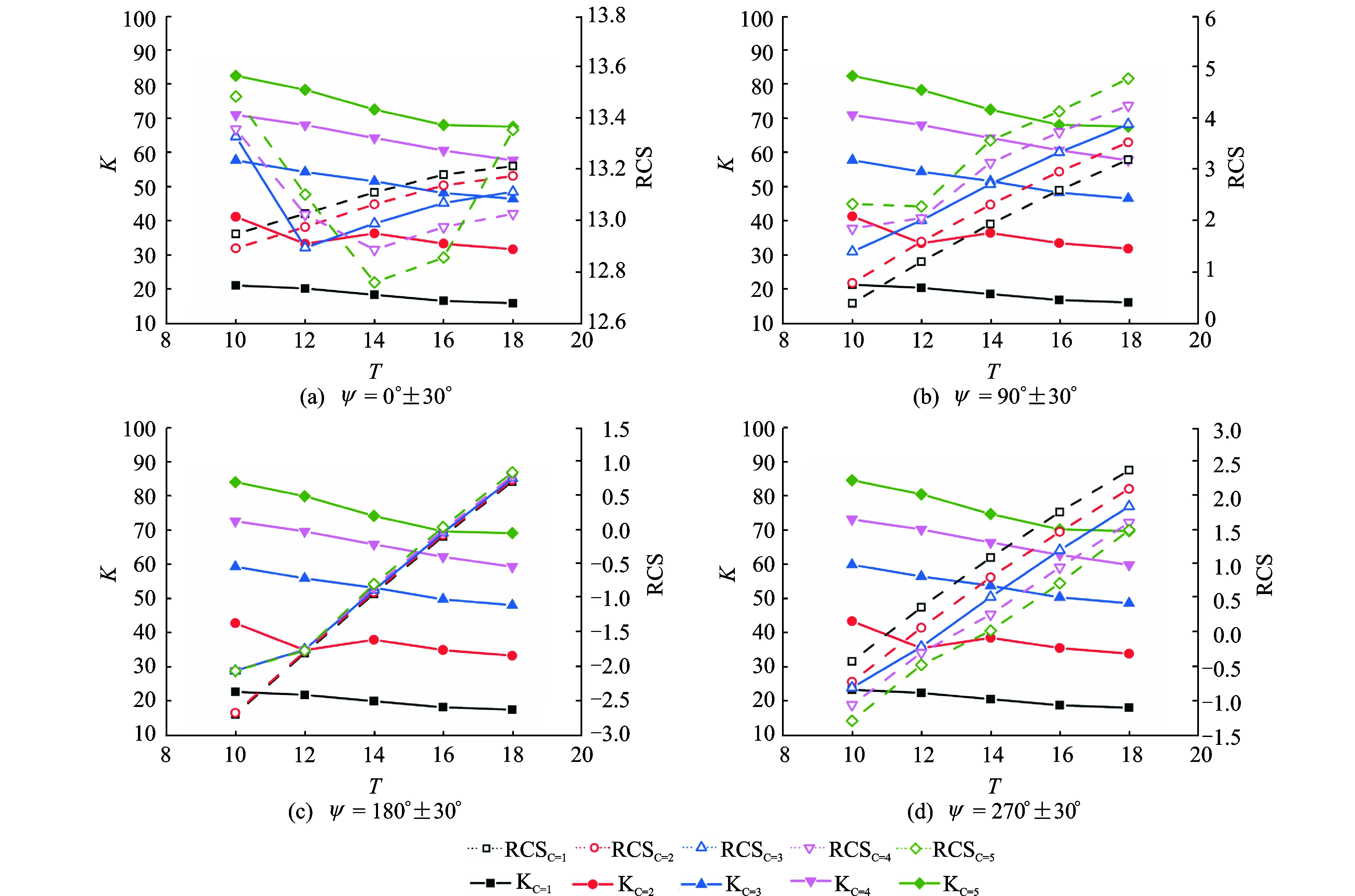
Fig.7 K and characteristics distribution of NACA series airfoils at four receiving azimuthal angles
3 Integrated Design on Aerodynamic and Stealth of Airfoil
3.1Integrated analyses
The integrated analyses about aerodynamic and stealth characteristics of airfoil are an MDO issue, and the shapes of airfoil that can improve aerodynamic performance and reduce RCS at the same time are usually inconsistent, so the key is to find the aerodynamic/stealth compromised conditions which can be described as Pareto front efficiently and accurately. The multi-objective problem can be transformed into a single objective problem by the linear weighted sum method.
NACA Cmax4Tmaxseries airfoils are selected for investigation. The samples about different thickness and camber combinations of NACA series airfoils are selected by FFD, then the aerodynamic/stealth characteristics of airfoils are calculated by CFD and FVTD methods respectively, and the fitting responses are obtained by the RBF. The total 25(5×5) samples (C=1—5,ΔC=1,T=10—18,ΔT=2) in design space, and the total 4 000 (50×80) fitting samples (C=1—5,ΔC=0.1,T=10—18,ΔT=0.1) in design space.
Fig.8 shows K and RCS distributions of NACA airfoil with different maximum thickness and camber combinations (ψ=180°±30°). As can be seen, a Pareto front denoting the increase of lift-to-drag ratio and decrease of the mean RCS has been calculated in Fig.8(b). The fitting 2D perspective projecting drawing about K and RCS distributions of different NACA airfoils are shown in Fig.8(c) and Fig.8(d), respectively. As a result, designers can choose the Pareto front or objective function with suitable constraints to find the optimized airfoil that satisfies the aerodynamic/stealth requirements at the same time in the fitting curved surface.

Fig.8 K and RCS characteristics of NACA series airfoils with different maximum thickness and camber combinations (ψ=180°±30°)
Fig.9 shows RCS characteristics about four receiving azimuthal regions (leading edge, upside, downside and trailing edge) of NACA Cmax4Tmaxseries airfoils with different maximum thickness and camber combinations. As can be seen, four receiving azimuthal regions of NACA airfoils have different Pareto fronts, and every one of regions has its corresponding K/RCS Pareto front. So the RCS responses about four important scattering regions are all important for a rotating blade due to its special motion style.
3.2Integrated design
Based on influence factors about aerodynamic performance and four scattering regions of rotor airfoil, the optimized airfoil can be designed by appropriate objective function and constraint condition.
Design status: Ma=0.4, Re=9×10⁶, angle of attack α=0°, TM wave incident angelφ=0°, L=10λ.
The lift-to-drag ratio and RCS mean value about leading edge (L), upside (U), downside (D), trailing edge (T) of airfoil are normalized:
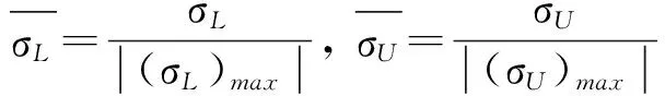

(11)
Objective function
(12)
(13)
Table 1shows the comparisons of weighted sum between baseline and optimized airfoil.The aerodynamic characteristics of NACA 5410 airfoil are the best,but RCS weighted sum at the four regions is not the minimum.The stealthy characteristics of NACA 1410 airfoil are the best,but aerodynamic performances(lift -to-drag ratio)are not optimum.When the maximum thickness is and the maximum camber is 4.3%,the combined airfoil satisfies the objective function and constraint condition.The weighted sum error between calculated and fitting sample from surro-gate model is small.As a result,it is demonstrated that the optimal method can satisfy the requirements of practical applications.

Fig.9 RCS characteristics of NACA airfoils with different maximum thickness and camber combinations

Table 1 Comparisons of weighted sum between baseline and optimized airfoil
Fig.10 shows the comparisons of aerodynamic and RCS characteristics between baseline and optimized airfoil. Although the optimized airfoil is not the optimum aerodynamic solution, its aerodynamic and stealth comprehensive performances are the best. Comparing with the RCS amplitudes of NACA1410 and NACA5410 airfoils (especially trailing edge 320°≤ψ≤340°), the RCS amplitudes of the optimized airfoil decrease significantly. At the same time, comparing with aerodynamic performances of NACA1410, the pressure distributions and the lift-to-drag ratio of the optimized airfoil are improved obviously.

Fig.10 Comparisons of aerodynamic and RCS characteristics between baseline and optimized airfoils
4 Conclusions
An integrated optimization design method about aerodynamic/stealth is developed for rotor airfoils, and the optimized airfoil can be designed by this method. From the results presented in this paper, the following conclusions can be drawn:
(1) The high precision numerical method utilizing the N-S and Maxwell′s equations can effectively simulate the characteristics about aerodynamic/stealth of rotor airfoils.
(2) Based upon surrogate model optimal techniques, an integration design of rotor airfoil about CFD/CEM coupling method is established, and it can be used to accurately and efficiently design the rotor airfoil with aerodynamic performance improvement and RCS reduction.
(3) The aerodynamic performances are significantly influenced by the maximum camber of airfoil, and the stealth characteristics are greatly influenced by maximum thickness of airfoil. The selection of rotor airfoil with high lift-to-drag ratio and low scattering characteristics is a process of seeking compromised requirements, and the optimal airfoil can be found through comprehensive analyses.
[1]STRAWN R C, CARADONNA F X, DUQUE E P N. 30 years rotorcraft computational fluid dynamics research and development[J]. Journal of the American Helicopter Society, 2006, 51(1): 5-21.
[2]SHANKAR V, HILL W, MOHAMMADIAN A H. A CFD-based finite-volume procedure for computational electromagnetic interdisciplinary applications of CFD methods:A1AA89-1987-CP[R]. 1989.
[3]CAMBEROS J A. COBRA-A FVTD code for electromagnetic scattering over complex shapes[R]. AIAA 02-1093, 2002.
[4]DEORE N, CHATTERJEE A. A cell-vertex finite volume time domain method for electromagnetic scattering[J]. Progress in Electromagnetics Research, 2010, 12:1-15.
[5]FUMEAUX C, KARAN K, VAHLDIECK R. Spherical perfectly matched absorber for finite volume 3D domain truncation[J]. IEEE Trans Microwave Theory Tech,2007, 55(12):2773-2781.
[6]HOANG V, DAM C P, HARRY A D. Airfoil shaping for reduced radar cross section[J]. Journal of Aircraft, 1994, 31(4):787-793.
[7]ZHU Z Q, FU H Y, YU R X, et al. Study on multi-objective optimization design of airfoil and wing[J]. Science in China (Series E), 2003, 33(11):999-1006. (in Chinese)
[8]ZHAO Q J, XU G H, ZHAO J G. Numerical simulations of the unsteady flowfield of helicopter rotors on moving embedded grid[J]. Aerospace Science and Technology, 2005, 9(2): 117-124.
[9]ZHAO Q J, XU G H, ZHAO J G. New hybrid method for predicting the flowfields of helicopter rotors[J]. Journal of Aircraft, 2006, 43(2):72-380.
[10]STOLCIS L, JOHNSTON L J. Solution of the Euler equations on unstructured grids for two-dimensional compressible flow[J]. Aeronautical Journal, 1990, 94(936):181-195.
[11]JOSEPH L S, WARMING R F. Flux vector splitting of the inviscid gasdynamic equations with application to finite-difference methods[J]. Journal of Computational Physics, 1981, 40(2):263-293.
[12]SHANG J S, GAITONDE D. Scattered electromagnetic field of a reentry vehicle[R]. AIAA 94-0231, 1994.
[13]HARDY R L. Multiquadric equations of topography and other irregular surfaces[J]. Journal of Geophysical Research, 1971, 76(8):1905-1915.
[14]TERRY L H. Viscous transonic airfoil workshop compendium of results: AIAA-87-1460[R]. 1987.
[15]CHATTERJEE A, MYONG R S. Efficient implementation of higher-order finite volume time domain method for electrically large scatterers[J]. Progress In Electromagnetics Research, 2009, 17:233-255.
Mr. Jiang Xiangwen is a Ph.D. student in aircraft design at Nanjing University of Aeronautics and Astronautics (NUAA), and his research interests are helicopter stealth design, helicopter CEM and helicopter CFD.
Dr. Zhao Qijun is a professor and Ph.D. supervisor in the College of Aerospace Engineering at NUAA, where he received his Ph.D. degree in aircraft design. His main research interests are helicopter CFD, helicopter aerodynamics, aerodynamic shape design of rotor blades, helicopter stealth design, active flow control of rotors and rotor aeroacoustics.
Mr. Zhao Guoqing is a Ph.D. student in aircraft design at NUAA, and his research interests are active flow control of rotor, helicopter CFD and helicopter aerodynamics.
Mr. Meng Chen is a master student in aircraft design at NUAA, and his research interests are helicopter stealth design and helicopter CEM.
(Executive Editor: Zhang Tong)
, E-mail address: zhaoqijun@nuaa.edu.cn.
How to cite this article: Jiang Xiangwen, Zhao Qijun, Zhao Guoqing, et al. Numerical optimization on aerodynamic/stealth characteristics of airfoil based on CFD/CEM coupling method[J]. Trans. Nanjing Univ. Aero. Astro., 2016,33(3):274-284.
http://dx.doi.org/10.16356/j.1005-1120.2016.03.274
V218Document code:AArticle ID:1005-1120(2016)03-0274-11
杂志排行

Transactions of Nanjing University of Aeronautics and Astronautics的其它文章
- Advances in Technologies of Piezoelectric Pumping with Valves
- Kinematic Calibration of Asymmetricly Actuated 6-DOF 3-PPPS Parallel Mechanism
- Kinematic Optimization of Bionic Shoulder Driven by PneumaticMuscle Actuators Based on Particle Swarm Optimization
- Dynamic Modeling and Adaptive Fast Nonsingular Terminal SlidingMode Control for Satellite with Double Rotary Payloads
- A Comprehensive Review on RNA-seq Data Analysis
- Joining Force of Heterogeneous Titanium Alloy in Linear Friction Welding Process