Numerical study of flow fluctuation attenuation performance of a surge tank*
2013-06-01GUOLanlan郭兰兰
GUO Lan-lan (郭兰兰)
School of Energy and Power Engineering, Shandong University, Jinan 250061, China
College of Mechanical and Electronic Engineering, Shandong University of Science and Technology, Qingdao 266590, China, E-mail: gllgo@163.com
LIU Zheng-gang (刘正刚), GENG Jie (耿介), LI Dong (李东), DU Guang-sheng (杜广生)
School of Energy and Power Engineering, Shandong University, Jinan 250061, China
Numerical study of flow fluctuation attenuation performance of a surge tank*
GUO Lan-lan (郭兰兰)
School of Energy and Power Engineering, Shandong University, Jinan 250061, China
College of Mechanical and Electronic Engineering, Shandong University of Science and Technology, Qingdao 266590, China, E-mail: gllgo@163.com
LIU Zheng-gang (刘正刚), GENG Jie (耿介), LI Dong (李东), DU Guang-sheng (杜广生)
School of Energy and Power Engineering, Shandong University, Jinan 250061, China
(Received September 11, 2013, Revised September 26, 2013)
The surge tank plays an important role in ensuring the stability of a water flow standard device. To study the influence of the structure and the working conditions on the regulator performance of a surge tank, a three-dimensional model, including a surge tank, the pipeline and the water tank is built, and the VOF model in the Fluent software is used to simulate the two-phase pulsatile flow in the surge tank. The inlet flow pulsation is defined by the User Defined Functions (UDF), and the outlet flow is set to be a free jet. By calculating the flow fluctuation coefficient of the variation under different flow conditions, the influences of the pulse frequency, the initial water level height and the baffle plate structure on the flow stability are analyzed. It is shown that the surge tank has a good attenuation effect on high-frequency pulsations, there is an optimal initial water level to suppress the fluctuations, the round holes of the baffle should ensure a certain circulation area with the bore diameter small enough to have the necessary damping effect.
surge tank, numerical simulation, VOF, flow stability
Introduction
The flow stability is an important feature and indicator of the water flow standard device, which is related directly with the repeatable verification of the flow meters and has an impact on the uncertainty calculation of differential pressure flowmeters[1]. The flow fluctuation is caused by the pressure pulsation at the water pump outlet. To stabilize the flow, a tower or surge tank is usually installed between the pump and the test line. The tower can ensure a constant pressure and achieve a good flow stability through the overflow. However, the tower has many shortcomings such as the limited pressure head, the long construction period, the high investment and the difficulty to relocation. The surge tank is a sealed pressure tank which uses the compressibility of the enclosed air and the baffle located in the tank to suppress the flow fluctuation. Compared with the tower, the surge tank can have a higher pressure head, a smaller size and a lower investment. So the surge tank is widely used by many small and medium enterprises, as well as scientific research and measurement institutions to ensure a constant water pressure of flow standard devices.
The surge tank is a kind of pulsation attenuator used to relieve the pressure and the flow pulsation in the pipeline. The studies of the pulsation attenuator involve the pulse generating mechanism, the process of the pulse transfer in the pipe, the performance of the attenuation and the matching between the attenuation and the system[2-6]. Reference [7] proposed mathematical models of the system by the wave method or the frequency method to study the attenuation performance, and the local pressure was assumed constant in the process of solving related equations, regardless of the shape of the cavity and the impact of the local pressure loss. References [8]-[10] made quantitative analyses of the structural parameters related with the attenuation performance impact, but the outlet pressurewas still treated as a fixed value, which is clearly incompatible with the actual situations. The flow in the surge tank is an air-water two-phase flow and is more complex than a single-phase flow. Reference [11] presented a simulation of the pure liquid phase flow, without considering the effect of the gas phase and the attenuation of the pulsating flow. This paper establishes a model that contains the surge tank, the pipelines and the water tank with an atmospheric pressure outlet, to simulate the two-phase flow in the surge tank by using the VOF numerical model. The jet boundary condition is used while the water flows into the water tank and the constant pressure boundary condition is used in the top of the water tank. The boundary conditions are consistent with the actual situation. On this basis, the flow stabilization performance of the surge tank is studied with the VOF model through using the Fluent software.
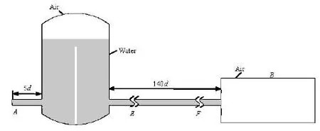
Fig.1 Calculation domain
1. Numerical models
In the surge tank are air-water two phase fluids. The free surface is simulated by the VOF model, with a volume fraction variable for each phase. The interface between the two phases is determined by solving for the volume fraction variable. In the surge tank is a turbulent flow, so the standardkε- turbulence model is used. The near-wall region is processed with the wall function.
1.1VOF model[12]
The continuity equation for the volume fraction
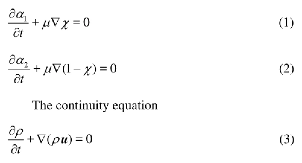
The momentum equation where (the subscript 1 represents the gas phase and the subscript 2 the liquid phase ):χis the volume fraction of the gas phase,ρis the density of the mixture,ρ=χρ1+(1-χ)ρ2,μis the viscosity coefficient,μ=χμ1+(1-χ)μ2,tis the time,uis the velocity vector of the two phase fluid,pis the pressure,gis the acceleration of gravity,Fis the equivalent volume force due to the surface tension.
1.2The standardkε-model[13]
kequation
wherekσandεσare the turbulent Prandtl numbers ofkandεcoefficients,kGis the turbulent kinetic energy produced by the gradient of the average velocity,bGis the turbulence kinetic energy produced by the flotage,MYexpresses the panting action caused bythe diffusivity of the compressible turbulent flow,1Cε,C2ε,C3εare constant coefficients, andSεandSkare the source items user-defined.
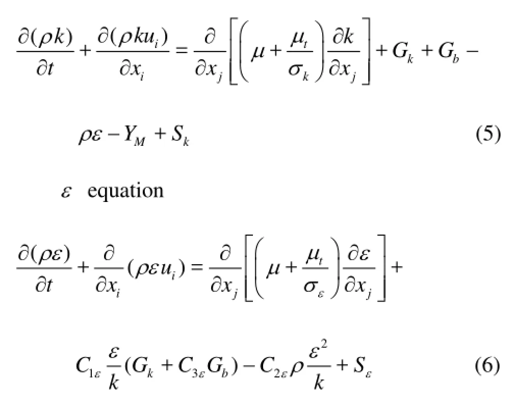
Fig.2 Structure sizes of the surge tank and baffle
2. The geometric model and boundary conditions
2.1Computing area and meshingThe c
alculation domain is shown in Fig.1. The water from the pump flows into the water tank after the pressure fluctuations are suppressed by the surge tank. At the initial time, the top of the surge tank and the whole water tank are filled with air, the bottom of the surge tank is filled with water. The surge tank is a cylindrical container, which is divided into inlet and outlet cavities by a vertical baffle. Their structure sizes are shown in Fig.2. The inner diameter of the surge tank isDb=0.28 m, its height is 0.5 m and the head radius isR=0.022 m. The height and the thickness of the baffle are 0.35 m and 0.004 m. The diameter of the round holes in the baffle isDh=0.02 m, and the space between them is 0.0044 m. Fig.3 shows grids of the surge tank. The round holes of the baffle and the head portion of the surge tank are meshed with unstructured grids, and the other area is meshed with structured grids. The grids in the round hole are refined, and the minimum mesh size is 0.002 m. The whole grid number is about 1.2×10⁶. By monitoring residuals (10–6for energy, and 10–3for others), the convergence of each calculation step is checked.
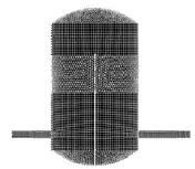
Fig.3 Grid meshing
2.2Boundary conditions
The flow fluctuation caused by the pressure fluctuation on the centrifugal pump outlet can be considered as in a sine form:Qi=Q+Δqsin(2πft), where the amplitude Δqis about 5% of the average flow rate14,15], f is the frequency of the pressure pulsation. A is the mass flow rate inlet and the sine periodic signal is defined by the UDF.Bis the pressure outlet.
3. Validation of the calculation method
The ab
ove settings are adopted to simulate the fluctuation flow. The flow stability of the monitor surface is represented by the flow fluctuation coefficient[ 15]

wheremδis the flow fluctuation coefficient,maxvqandminvqare, respectively, the maximum and the minimum instantaneous flow at a certain flow rate.
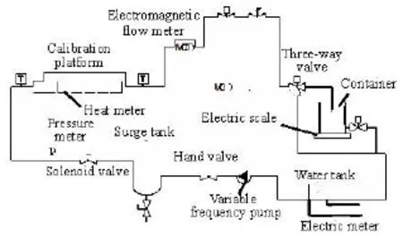
Fig.4 Experimental set-up
The average flow rate at the surge tank inlet isQ=5.4 m3/h, the pulsation frequency isf=10 Hz and the amplitu de is Δq=5%/Q. In order t o verify thecorrectnessofthenumericalcalculation,experi-mental measurements using the same equipment (see Fig.4.) are made, and 60 instantaneous flow rates are recorded with the electromagnetic flow meters to calculate the flow fluctuation coefficient. A comparison of the results is shown in Table 1.

Table 1 Comparison of experimental and numerical values
4. Numerical calculation and analysis
The effect of the surge tank is related to many factors, such as the pulse frequency, the structure or state parameters, the installation position and the pipeline characteristics[14].
4.1Influence of the pulsation frequency on the flow stability
The flow rate3of the centrifugal pump before the surge tank is 8 m/h and its head is 65 m. In Ref.[14]where the pump is a closed structure with a small flow rate and a high head, the frequency of the3outlet pulsation is low. When the flow rate is 2.8 m/h, the main characteristic frequencies are 3 times, 5 times and 6 times of 1 Hz, 10 Hz, 36 Hz, 44 Hz, 29 Hz. So the simulations are carried out at the same flow rate point at frequencies of 2 Hz, 3 Hz, 5 Hz, 10 Hz, 20 Hz, 30 Hz, 40 Hz and 50 Hz.
Figure 5 shows the flow fluctuation coefficients at pulsation frequencies from 2 Hz to 50 Hz. It can be seen that when the frequency increases, the pulsation attenuation ratio of the flow rate is decreased. That is because the cycle of the low-frequency pulsation is longer than that of the high-frequency pulsation, and much more water flows into the surge tank at the same time. The volume of the air changes greatly, so does the pressure, which lowers the flow stability.
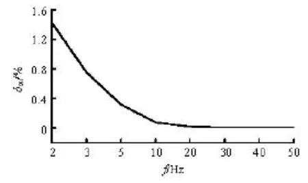
Fig.5 Flow fluctuation coefficients at different frequencies
Figure 6 shows the pulsation attenuation rate of the flow rate and the pressure at different frequencies. From Fig.5, it can be seen that the variation trend of the flow rate’s pulsation attenuation rate is in accordance with the pressure’s pulsation attenuation rate, which means that the surge tank suppresses both the pressure and the flow rate pulsation.
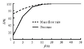
Fig.6 Pulsation attenuation ratios at different frequencies
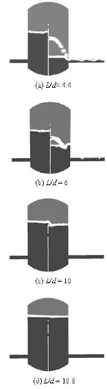
Fig.7 Volume fraction cloud maps under different initial water levels
4.2Influence of the initial water level on the flow stability
The flow field is simulated at a frequency of 10 Hz with different water levelsL. The contour of the water’s volume fraction is shown in Fig.7. It can be seen that when /=Ld4.4 and /=Ld6, the waterlevel of the inlet cavity is lower than the height of the baffle and there is a big water level difference between the two cavities. The water is injected into the outlet cavity through the round holes in the baffle, which causes large fluctuations. Due to the low water level of the outlet cavity, the air at the free surface is sucked into the outlet pipe. As the water level drops, the suction occurs more frequently and more bubbles are created.
When /=Ld10 and /=Ld10.8, the water level of the inlet cavity is higher than the height of the baffle and is equal to that of the outlet cavity, therefore, the outlet is immersed in the water and the suction of the air is avoided.
Figure 8 shows the flow fluctuation coefficients with /=Ld8.4, 9.2, 10 and 10.8. It can be seen thatmδincreases with the water level, which shows that the air volume affects the flow stabilization. Too small volume of the air will hamper the surge action.
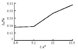
Fig.8 Flow fluctuation coefficients with different initial water levels
To sum up, too high or too low water level is not good for the flow stabilization. Due consideration of various aspects points to a conclusion that /=Ld9.2 is the most reasonable initial water level. That means that the air-water volume ratio in the surge tank is about 1/2.
4.3Influence of the baffle structure on the flow stability
The layout of the round holes in the baffle is shown in Fig.2(b). Simulations are carried out whenDh, respectively, is 0.01 m, 0.015 m, 0.018 m, 0.02 m, 0.022 m, 0.025 m and 0.03 m (f=10 Hz,L/d=9.2). Figure 9 shows the flow fluctuation coefficients with different initial water levels. It can be seen that whenDh=0.02 m and 0.022 m, the flow is most stable. WhenDhis less than 0.02 m,δmincreases evidently. This is because the circulation area is too small to let the water in the inlet cavity flow into the outlet cavity in time. So a water level difference between the inlet cavity and the outlet cavity will result in large fluctuations, as is shown in Fig.10(a). And the low water level of the inlet cavity is prone to bring bubbles into the outlet pipe. Figure 10(b) shows the contour of the water volume fractions whenDh=0.03 m. The water circulation area is enough to keep the water levels of the two cavities at the same surface, so the flow is more stable than whenDh=0.01 m. But with the increase of thehD, the drag coefficient of the baffle is decreased which reduces the surge effect on the water flow. So the curve ofmδrises slightly whilehDis larger than 0.022 m.

Fig.9 Flow fluctuation coefficients with different hole diameters

Fig.10 Contours of water’s volume fraction
5. Conclusions
The influence of the two-phase flow on the pressure pulsation is studied based on the VOF model of CFD and the results are verified by experiments, which provide a large number of significant scientific data and theoretical guidance to the same type of flow.
The initial water level in the surge tank is closely related with the surge effect. If the initial water level is too low, there will be a large water level difference between the inlet cavity and the outlet cavity, which make it easy to form the hit impact on the water surface and to suck the air into the outlet pipe. On the other hand, if it is too high, there will be no enough air to reduce the flow fluctuation. So the best surge effectwill be achieved when the volume ratio of air to water is about 0.5. The surge tank has a better attenuation effect on a higher frequency pressure pulsation. The pulsation attenuation ratio reduces rapidly when the pulsation frequency is lower than 10 Hz. The circulation area of the baffle holes should ensure a small water level difference between the inlet and outlet cavities. Then the diameter can be reduced properly to increase the absorption and the surge to the flow fluctuation. The application of the jet exit can provide a certain back pressure to the flow, as well as remove the bondage of the export conditions on the pulsation. One has to deal with a multiphase compressible problem in the study of the pulsation.
[1] CHINA NATIONAL BUREAU OF TECHNICAL SUPERVISION, JJG164-2000.Chinese National Standards[S]. Beijing, China: Standards Press of China, 2000-06-01(in Chinese).
[2] LAI Xu, YANG Jian-dong and CHEN jian-zhi. Effects of velocity head and momentum exchange on critical stable sectional area of downstream throttled surge tank[J].Journal of Energy Engineering,2003, 129(3): 96-106.
[3] FAANES A., SKOGESTAD S. Buffer tank design for acceptable control performance[J].Industrial and Engineering Chemistry Research,2003, 42(10): 2198-2208.
[4] ORTWIG H. Experimental and analytical vibration analysis in fluid power systems[J].International Journal of Solids and Structures,2005, 42(21-22): 5821-5830.
[5] KIM S. H. Impluse response method for pipeline systems equipped with water hammer protection devices[J].Journal of Hydraulic Engineering, ASCE,2008, 134(7): 961-969.
[6] FAANES A., SKOGESTAD S. A systematic approach to the design of buffer tanks[J].Computers and Chemical Engineering,2004, 24(2): 1395-1401.
[7] KIM S. H. Design of surge tank for water supply systems using the impulse response method with the GA algorithm[J].Journal of Mechanical Science and Technology,2010, 24(2): 629-636.
[8] SHAN Chang-ji, LIU Xian-hong and WANG Guo-zhi. Flow Characteristics CFD resolution of pressure pulsation attenuator of high pressure piston pump[J].Machine tool and Hydraulics,2005, (7): 113-114(in Chinese).
[9] ZHANG Yin, Yu Jun and LI Shen et al. Experimental research and CFD simulation of pressure pulsation attenuator[J]. Chinese Hydraulics and Pneumatics,2011, (6): 47-50(in Chinese).
[10] AN Jian-feng, ZHANG Jian and YU Xiao-dong et al. Influence of flow field on stability of throttled surge tanks with standpipe[J].Journal of Hydrodynamics,2013, 25(2): 294-299.
[11] LI Zheng. Study on uncertainty and flow stability of water flow standard device[D]. Master Thesis, Tianjin, China: Tianjin University, 2009(in Chinese).
[12] YUAN Ming-hao, YANG Yan-hua and LI Tian-shu et al. Simulation of free surface with phase change based on a VOF method[J].Journal of Engineering Thermophysics,2007, 28(6): 961-964(in Chinese).
[13] LIU Yong-hui, DU Guang-sheng and LIU Zheng-gang. The influence of different design parameters and working conditions on characteristics of heat meter[J].Journal of Hydrodynamics,2009, 21(3): 394-400.
[14] LI Yan-min, ZHANG Zhi-hui and ZHANG yong, Analysis of the flow field and optimal design for certain pressure pulsation attenuator based on fluent[J].Machine Tool and Hydraulics,2010, 38(11): 86-88(in Chinese).
[15] SU Yan-xun, LIANG Guo-wei and SHENG Jian.Flow measurement and testing[M]. Beijing, China: China Metrology Publishing House, 2007(in Chinese).
10.1016/S1001-6058(13)60443-6
* Project supported by the National Natural Science Foundation of China (Grant No. 10972123).
Biography: GUO Lan-lan (1979-), Female, Ph. D. Candidate, Lecturer
DU Guang-sheng,
E-mail: du@sdu.edu.cn
猜你喜欢
杂志排行

水动力学研究与进展 B辑的其它文章
- Experimental study by PIV of swirling flow induced by trapezoid-winglets*
- Cavitation bubbles collapse characteristics behind a convex body*
- Experimental study of the interaction between the spark-induced cavitation bubble and the air bubble*
- A preliminary study of the turbulence features of the tidal bore in the Qiantang River, China*
- The calculation of mechanical energy loss for incompressible steady pipe flow of homogeneous fluid*
- Analysis of shear rate effects on drag reduction in turbulent channel flow with superhydrophobic wall*