Characterization and application in XRF of HfO2-coated glass monocapillary based on atomic layer deposition*
2021-05-24YanLiLi李艳丽YaBingWang王亚冰WeiErLu卢维尔XiangDongKong孔祥东LiHan韩立andHuiBinZhao赵慧斌
Yan-Li Li(李艳丽), Ya-Bing Wang(王亚冰), Wei-Er Lu(卢维尔),Xiang-Dong Kong(孔祥东), Li Han(韩立), and Hui-Bin Zhao(赵慧斌)
1Institute of Electrical Engineering,Chinese Academy of Sciences,Beijing 100190,China
2College of Nuclear Science and Technology,Beijing Normal University,Beijing 100875,China
3Institute of Microelectronics,Chinese Academy of Sciences,Beijing 100029,China
4University of Chinese Academy of Sciences,Beijing 100049,China
Keywords: x-ray optics,monocapillary,atomic layer deposition,HfO2 film
1. Introduction
Monocapillary, a single hollow tube, is a popular device for x-ray focusing and collimation.[1,2]It usually presents a cylindrical, conically tapered, paraboloidal or elliptical shape[3–5]and is mainly used to obtain a small x-ray beam for experiments such as micro-x-ray fluorescence (micro-XRF)instrument[6,7]and x-ray nano-imaging system.[8,9]In monocapillary, only the portion of x-rays with incident angles less than the critical angle can be totally reflected on the inner wall of the tube and transmitted through the hollow core region.The critical angle for total reflection is determined by the complex index of refraction n,
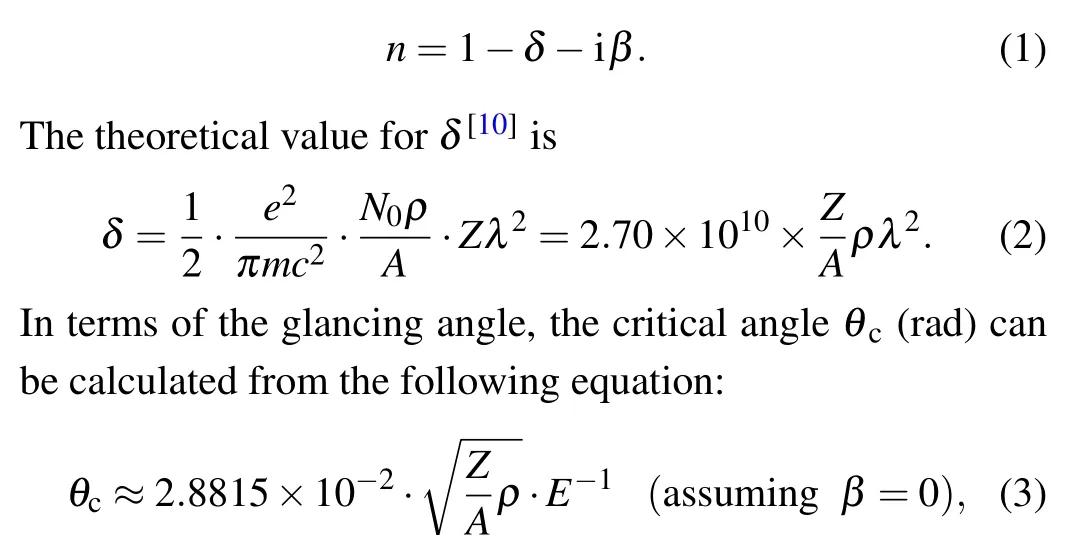
where Z is the atomic number,A the atomic mass,ρ (in units g/cm3) the density of the reflective material, and E (in unit keV) the energy of the incident x-rays. It can be inferred that for the same monocapillary the higher the value of E,the smaller the value of θcwill be.
Due to the easy processing and smoothness of surface,glass is the most common material for both monocapillary[11]and polycapillary.[12]However, the glass density is relatively low (2.2 g/cm3), which leads to a small θc, indicating that part of the high energy incident x-rays emitted from an x-ray tube cannot be totally reflected by the inner wall of the monocapillary. Increasing θcis believed to be an efficient way to improve the transmission characteristics by totally reflecting more higher energy x-rays. From this point of view, it can be seen from Eq. (3) that to increase the value of θchighdensity material is an ideal choice for the capillaries. That is why the metal monocapillaries have received wide attention since 1996. Several methods have been developed to produce ‘segmented’ and ‘pressed’ metal monocapillaries. Nevertheless,the shapes of those monocapillaries are far from the design because of narrow etching grooves[10]and horizontal wedges[13]respectively. Although the process of manufacturing‘segmented’monocapillaries is further optimized[14,15]and monocapillaries with precise shape can be obtained, the smoothness of inner surface can still not be well controlled.Therefore another idea is proposed. That is to coat a highdensity film in the inside of capillary and many researchers have tried this method. In 2005 Matsuura et al.[2,16]fabricated nickel-coated monocapillaries by a plating method. In order to achieve better adhesion of the nickel layer onto the glass,the surface of the silica was sensitized with ammonium fluoride solution, which resulted in some clusters of nickel on the surface. In 2010 Nakazawa and Nakano[17]used the same method to gain Au-coated monocapillaries and observed the enhancement of XRF intensity,which implies the performance improvement of metal-coated monocapillaries. Unfortunately,owing to the extremely high length–diameter ratio of the capillary,it is still difficult to obtain thin film with uniform thickness and low roughness.
Atomic layer deposition (ALD) is a vapor phase deposition technique based on the sequential use of self-limiting chemical reactions, which ensures the conformality, uniformity and atomic level control of film. Compared with other vapor phase thin film growth methods such as chemical vapor deposition (CVD) or physical vapor deposition (PVD),the ALD due to the self-limiting growth, can be used to deposit a highly homogeneous thin film on the surface of curved substrate without additional manipulation such as rotating the substrate. Until now a variety of films have been successfully deposited by the ALD on many types of substrates such as Si wafers,[18,19]Si nanowires,[20]and glass fiber cores.[21,22]Therefore the ALD is a promising way to coat capillary. And through optimizing the process and improving the equipment,the ALD presents potential applications in coating polycapillary with a diameter less than 10 µm or coating multilayerfilm on the inner surface of capillary which is an important x-ray monochromic component. That is of great significance for applying capillaries to more x-ray fields. Our previous work[23]demonstrated that the ALD is a feasible way to coat glass monocapillary with a short length of 5 cm and the coated monocapillary shows an increased acceptance angle for 16.8-keV x-ray while high reflectivity is still retained. Here in this work,the ALD is used to deposit HfO2film on the inner surface of monocapillary which is nearly twice as long as the former one,and possesses a higher length-diameter ratio. Based on the working principle, it is known that generally highdensity-film coated glass monocapillary with a higher lengthdiameter ratio will totally reflect more high-energy x-rays if space allows. And monocapillary with length ~10 cm is commonly used.[2,16,17]The HfO2film is selected considering the fact that its density is higher than that of glass and it is chemically stable with melting temperatures as high as 2758°C.The transmission process of x-ray with energy from 5 keV to 100 keV through the HfO2-coated monocapillary is analyzed in detail. The HfO2-coated monocapillary is used in an XRF system and spectrum of a Mo sample is measured.
2. Experiments
2.1. Coating
A tapered borosilicate glass monocapillary was drawn and used to grow HfO2film on the inner wall. The length(L),input diameter (ID), and output diameter (OD) of the monocapillary are listed in Table 1. And the monocapillary was designed to focus x-rays by single total reflection.The HfO2film was deposited using a commercial Ke-Micro T-ALD 100A setup. The ALD was performed using sequential exposures of TDMAH (Hf(N(CH3)2)4) and H2O separated by a purge of nitrogen with a flow rate of 14 standard cubic centimeters per minute (sccm). The deposition cycle for HfO2consisted of 0.13-s pulse of TDMAH,50 s of purging with nitrogen followed by 0.02-s pulse of H2O and 50 s of purging with nitrogen. The 3000 ALD cycles were set to deposit on the inner wall of glass monocapillary. The typical growth rate for HfO2coating is 0.95 ˚A per cycle. The deposition temperature and pressure were 250°C and 0.1 Torr(1 Torr=1.33322×10²Pa)respectively. Scanning electron microscope (SEM) was utilized to observe the cross-section of the HfO2-coated monocapillary.
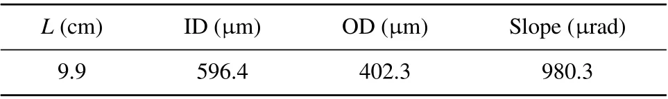
Table 1. Parameters of tapered monocapillary.
2.2. Measurement
The spectra of x-rays focused by the tapered monocapillary before and after coating were measured. Figure 1(a)shows the measurement system consisting of an x-ray tube,a beamstop (a lead round ball with diameter ~300 µm), a monocapillary, a Pb plate, and an x-ray detector. The x-ray tube with a W target(L9631 HAMAMATSU,Japan)was operated at 10 W(100 kV,100µA)and the size of the x-ray source was ~21 µm. The beamstop was used to block the direct xrays. A Pb plate with about 1-mm-diameter pinhole aligning to the exit of the monocapillary could effectively shield the primary x-rays from the source and‘penetration halo’x-rays.[24]A high energy x-ray detector (X-123 CdTe AMETEK, USA)was used to obtain the spectra. F was set to be 20 cm. The detecting time was 5 min.
The spactra of XRF were detected by using the uncoated and HfO2-coated monocapillarie. Figure 1(b) presents the measurement system. The x-ray tube was operated at 10 W(50 kV,200µA).The beam-stop was used to block the direct x-rays for avoiding the influence of the direct x-rays on the results of XRF.A Mo sample was used and a silicon drift detector system (AXAS-M KETEK, Germany) was utilized to collect the XRF spectrum. The value of F, D, and σ were fixed at 20 cm, 10 cm, and 45°respectively. The detecting time was 10 min.
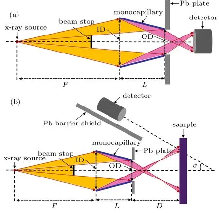
Fig.1. Sketch of measurement system of spectra of(a)x-rays and(b)XRF by using monocapillary.
3. Results and discussion
3.1. Transmission of x-rays
Figure 2 shows the primary spectrum of the x-ray tube(through a pinhole) and the spectra of x-rays through monocapillary before and after coating. The normalized energy spectrum is obtained through dividing the counts by the highest count of the spectrum. In area 1 the spectrum of x-rays focused by uncoated monocapillary (blue curve) falls rapidly from the blue point at 13.3 keV to the bottom 18.1 keV and that focused by HfO2-coated monocapillary (red curve) falls from red point at 18.7 keV to the bottom 33.0 keV. Therefore,it can be seen that the energy range of x-rays focused by HfO2-coated monocapillary is broadened obviously. Figure 3 helps to further understand the propagation of x-rays in the monocapillary. Reflex angle of the incident x-rays reflected by inner surface of the monocapillary goes from θ to θ′. The value of θ, which depends on F, L, ID, and OD, determines the highest energy of x-ray that can be totally reflected on the entire inner surface of the monocapillary. And the value of θ′determines the highest energy of x-ray the monocapillary can focus. According to Eq. (3), for the glass monocapillary before being coated in this work, the highest energy of x-ray reflected on the entire inner surface of the monocapillary is calculated to be 12.1 keV and the highest energy the monocapillary can focus is 17.8 keV, which is basically consistent with the blue curve in area 1 in Fig.2. Hence the high energy x-rays in a range between 13.3 keV and 18.1 keV can be completely reflected on the inner surface. However,as the energy goes up in this range,the reflective area of the inner surface decreases,which results in the decreasing of x-ray intensity from 13.3 keV and 18.1 keV presented in the spectrum(blue curve).As for HfO2-coated monocapillary,due to the increase of total reflection critical angle,the energy range of x-rays which can be reflected obviously shifts towards high energy region. Theoretically the highest energy of x-ray reflected on the entire inner surface of the HfO2-coated monocapillary is calculated to be 23.0 keV and the highest energy the monocapillary can focus is 33.8 keV. In Fig. 2, it is not difficult to find that the red curve between 18.7 keV and 33.0 keV includes two pieces of slopes separated at 23.3 keV. Considering the fact that the density of the HfO2film is generally less than 9.85 g/cm3,the theoretically calculated energy range from 23.0 keV to 33.8 keV is basically consistent with the second slope range from 23.3 keV and 33.0 keV.Nevertheless, why the peak appears at 18.7 keV is not known exactly. Maybe it results from the non uniform distribution of HfO2film along the monocapillary and it makes the transmission process of x-rays more complicated. For example, the thicker film on the inner wall of the monocapillary may be right in the path of some totally reflected x-rays and the x-rays have to pass through the film,thereby lead the transmission efficiency and x-ray intensity to decrease.
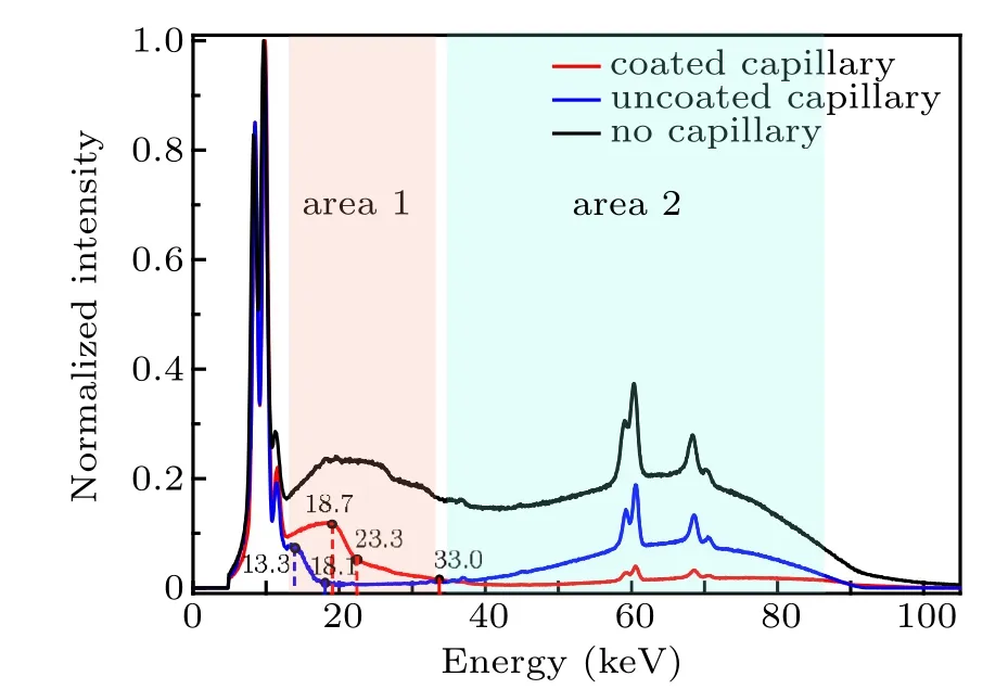
Fig. 2. Primary spectrum of x-ray tube, x-rays through HfO2-coated monocapillary and uncoated monocapillary, with area 1 and area 2 indicating relatively low and high energy regions respectively.
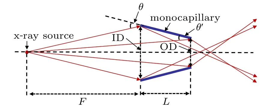
Fig.3. Sketch of reflection of incident x-rays on inner surface of monocapillary,where θ and θ′ are incident angles of x-rays at entrance and exit of monocapillary.
In addition,in area 2 the spectrum of x-rays through uncoated monocapillary goes up at 35 keV and it has the same trend as the primary spectrum after 35 keV.That is mainly attributed to the effect of‘penetration halo’ which results from the high energy x-rays penetrating through the wall of monocapillary and being detected by the x-ray detector. Therefore some x-rays with energy >35 keV passing through the uncoated monocapillary leads the intensity in the high energy range to increase. At the same time, it can be seen that the spectrum of the HfO2-coated monocapillary presents no significant increase in that range. Based on that, it could be inferred that high-density HfO2film absorbs more high energy x-rays and less x-rays leak outside the monocapillary. And the‘penetration halo’is suppressed to some extent.
3.2. XRF spectrum
Figure 4 shows the XRF spectrum of the Mo sample obtained by using uncoated(green curve)and HfO2-coated(red curve) monocapillary. The normalized energy spectrum is acquired through dividing the counts by the highest count of the spectrum. In Fig. 4, it can be seen that the two spectra present many peaks,which is because the Mo sample contains a variety of impurity elements. As it is known that only the x-rays with energy higher than the absorption edge of some element can go through monocapillary,the characteristic peaks can appear on the spectrum. The two spectra present peaks at the same positions in the range with x-ray energy <15 keV,which means that the uncoated and coated monocapillary both can focus x-rays whose energy is high enough to excite these characteristic peaks. However,the key difference between the two spectra is that two more peaks occur at ~17.4 keV and~19.6 keV on the red curve. Considering the influence of the energy resolution of the detector,these two peaks are regarded as the characteristic x-rays of Mo Kα(17.48 keV) and Kβ(19.606 keV).[25]To excite these two characteristic x-rays of Mo, the energy of the incident x-ray on the sample must be higher than the absorption edge of Mo (20.0 keV). From the analysis in Subsection 3.1, the highest energy the uncoated monocapillary can focus is 18.1 keV,which leads no K-series characteristic x-rays of Mo to appear on the green curve. The highest energy the HfO2-coated monocapillary can focus is 33.0 keV and hence two strong peaks occur on the red curve.Therefore the ability of HfO2-coated monocapillary to focus more higher energy x-rays can help to improve XRF measurement.
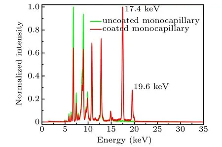
Fig.4. Sspectrum of XRF obtained by uncoated monocapillary and HfO2-coated monocapillary.
3.3. HfO2 film
Figure 5 shows SEM images of the cross-section of HfO2-coated monocapillary in the middle area. The close up and overall view of monocapillary center hole are presented in the left image and the right image. The thickness of HfO2film is ~150 nm. In addition, film thickness values at other two positions,~2 cm from input/output end of the monocapillary,are presented in Fig. 6 and they are both ~200 nm. It can be seen that the film thickness varies along the monocapillary and the specific thickness distribution needs to be further investigated in future. The thickness is less than 300 nm which is the theoretical value of the HfO2film considering the fact that the typical growth rate of HfO2on a flat substrate is about 0.95 ˚A per cycle. The main reason may be that the ALD setup used in this experiment is a common equipment designed for growing film on flat or regular curved substrates. The high length-to-diameter ratio of the monocapillary makes it difficult to control the growth process. The precursor gases,TDMAH(Hf(N(CH3)2)4)and H2O,may be not uniformly adsorbed to the inner surface during every cycle and non-uniform HfO2film forms along the monocapillary.
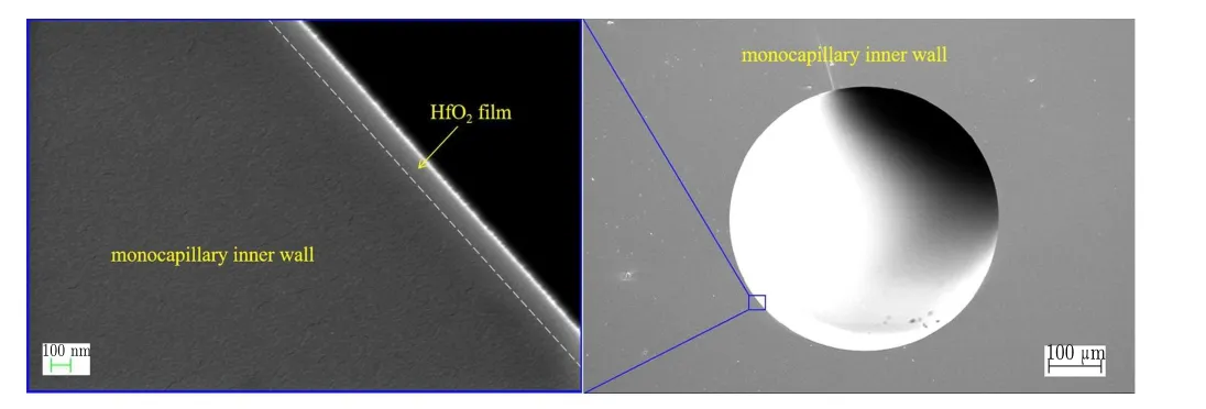
Fig. 5. SEM images of cross-section of HfO2-coated monocapillary in the middle area.
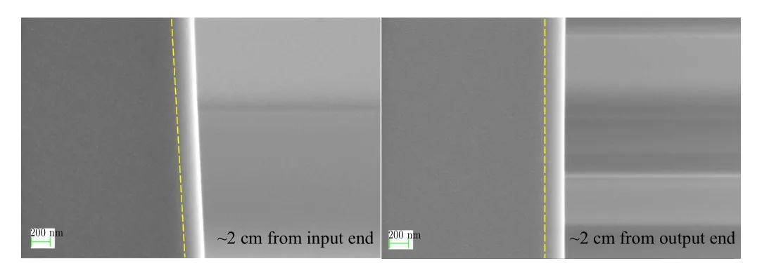
Fig.6. SEM images of cross-section of HfO2-coated monocapillary near the two ends.
4. Conclusions and prospects
The results described in this work validate the feasibility of ALD to grow HfO2film on the inner wall of larger lengthto-diameter ratio monocapillary with length 9.9 cm, entrance diameter 596.4 µm, and exit diameter 402.3 µm. And the HfO2-coated monocapillary shows improved properties. The energy upper limit of focused x-rays increases from 18.1 keV to 33.0 keV and the ‘penetration halo’ is suppressed to some extent. When the HfO2-coated monocapillary is used in XRF system, more high energy characteristic x-rays are obtained without changing any parameters of the measurement system.Due to the film growth mechanism, the ALD is a promising method to grow single or multilayer film on the inner surface of monocapillary and even polycapillary,which is of great significance for expanding the application field of capillary x-ray optics. In future, research will focus on the growth of film and more applications of the coated capillary. In order to allow the uniform growth of film in a controlled way, critical components of the ALD setup and the deposition process will need to be redesigned and optimized. And the thickness distribution of the film along the monocapillary and its influence on the transmission process will need to be investigated in detail. Besides, some more high-density films such as Ir and Pt can also be deposited inside the capillary to further explore the transmission properties.
猜你喜欢
杂志排行

Chinese Physics B的其它文章
- Corrosion behavior of high-level waste container materials Ti and Ti–Pd alloy under long-term gamma irradiation in Beishan groundwater*
- Degradation of β-Ga2O3 Schottky barrier diode under swift heavy ion irradiation*
- Influence of temperature and alloying elements on the threshold displacement energies in concentrated Ni–Fe–Cr alloys*
- Cathodic shift of onset potential on TiO2 nanorod arrays with significantly enhanced visible light photoactivity via nitrogen/cobalt co-implantation*
- Review on ionization and quenching mechanisms of Trichel pulse*
- Thermally induced band hybridization in bilayer-bilayer MoS2/WS2 heterostructure∗