Intelligent Reflecting Surface Assisted Transmission Optimization Strategies in Wireless Networks
2024-04-28HeXinxinQiXuanMengWeiLiuWeiYinChangchuan
He Xinxin,Qi Xuan,Meng Wei,Liu Wei,Yin Changchuan
School of Electronic Engineering,Beijing University of Posts and Telecommunications,Beijing 100876,China
Abstract: Wireless Power Transfer (WPT) technology can provide real-time power for many terminal devices in Internet of Things (IoT) through millimeter Wave(mmWave)to support applications with large capacity and low latency.Although the intelligent reflecting surface (IRS) can be adopted to create effective virtual links to address the mmWave blockage problem,the conventional solutions only adopt IRS in the downlink from the Base Station (BS) to the users to enhance the received signal strength.In practice,the reflection of IRS is also applicable to the uplink to improve the spectral effciiency.It is a challenging to jointly optimize IRS beamforming and system resource allocation for wireless energy acquisition and information transmission.In this paper,we frist design a Low-Energy Adaptive Clustering Hierarchy(LEACH)clustering protocol for clustering and data collection.Then,the problem of maximizing the minimum system spectral effciiency is constructed by jointly optimizing the transmit power of sensor devices,the uplink and downlink transmission times,the active beamforming at the BS,and the IRS dynamic beamforming.To solve this non-convex optimization problem,we propose an alternating optimization(AO)-based joint solution algorithm.Simulation results show that the use of IRS dynamic beamforming can signifciantly improve the spectral effciiency of the system,and ensure the reliability of equipment communication and the sustainability of energy supply under NLOS link.
Keywords: intelligent reflecting surface (IRS);joint optimization;millimeter wave;wireless information transmission(WIT);wireless power transfer(WPT)
I.INTRODUCTION
With the beneftis from the intensive research and development of various advanced communication technologies such as millimeter Wave (mmWave) communication and Multi-Input Multi-Output (MIMO),5G/B5G can have a large network capacity,provide a secure and reliable connection and meet the quickly increasing demand the 5G era and the massive access of IoT devices in the future[1][2].In other ways,the advanced 5G/B5G technologies are also accompanied by high hardware costs and high energy consumption[1] [3],which limits their deployment and application in real wireless networks.To solve the problem of node energy limitation,the research of wireless energy transmission network has attracted wide attention from academia and industry[4][5].The network is based on WPT technology that supports far-feild electromagnetic wave transmission,and uses dedicated wireless energy transmission nodes to provide energy[6]for the operation of communication equipment by transmitting electromagnetic waves in the air.WPT transmits energy to the equipment by emitting mmWave to provide power for its operation of communication [7] [8] [9][10].The current directional narrow beam beamforming technique can effectively compensate the high propagation loss in mmWave band.However,the vulnerability of mmWave communication in non-line-of-sight(NLOS)link state can seriously deteriorate link quality,resulting in a decrease in WPT effciiency.As a result,improving energy eff-i ciency and lowering energy consumption are still crucial issues in wireless energy transmission.
To address this issue,intelligent reflecting surface(IRS),as the current research hotspot of 6G,has emerged as a revolutionary and innovative technology to establish a robust mmWave connections even when the line-of-sight (LOS) link is blocked by obstacles [11] [12].Specifcially,IRS is a low hardware cost planar array composed of a large number of reconfgiurable passive reflective elements that can use intelligent controllers to reflect electromagnetic waves with controllable phase shift.By reasonably confgiuring the reflection phase shift of IRS elements,IRSs can help create effective virtual LOS links and make the reflected signals coherently combined with the signals of other paths at the receiver to obtain higher passive beamforming gain,resulting in a more reliable mmWave connection [11] [12].The application of IRS in mmWave band WPT technology is undoubtedly very promising to solve the inherent problems of low wireless energy and information transmission effciiency.IRS can be used as a special intelligent passive relay to assist the equipment under the NLOS link in wireless energy transmission and communication,which will effectively solve the blockage problem and improve energy collection effciiency.
While prior works in [13][14][15][16][17] mainly focus on exploiting IRS for wireless information transmission,the high beamforming gain brought by lowcost IRS is also appealing for WPT.In particular,without the need of any transmit RF chains,IRS enables intelligent signal reflection over a large aperture to compensate the high RF signal attenuation over long distance and thereby creates an effective energy harvesting/charging zone in its neighborhood.In recent years there has been a lot of IRS assistance in energy harvesting and beamforming.[18] proposed a new framework for energy collection and information transmission of WPCN assisted by IRS based on nonorthogonal multiple access(NOMA).The total transmission capacity is maximized by the joint optimization of energy beamforming,information beamforming,and IRS phase shift.[19] proposes a new concept of multifunctional reconfgiurable smart surfaces(MF-IRSs),in which IRS can be used for reflection,signal amplifciation and energy harvesting.By harvesting energy from the incident signal,MF-IRS is able to simultaneously reflect and amplify the signal without an external power source.In [20][21],IRS has also been mentioned for assisting wireless powered communication networks.In [22],it is mentioned that the system gain can be effectively amplifeid by appropriately adjusting the phase shift of the IRS reflector element,and the results show that the proposed IRS-based resource allocation method can provide high energy effciiency of up to 300% compared with the use of conventional multi-antenna amplifeid relay.[23]also presents a problem of maximizing the energy effciiency of IRS-assisted simultaneous wireless information and power transfer(SWIPT)systems by adjusting the reflected phase shift of IRS.A SWIPT system aided by the IRS has been proposed in [24],where an IRS is deployed to assist a multiantenna BS to serve multiple information decoding receivers and energy harvesting receivers.The authors aimed to maximize the weighted sum-power received by energy harvesting receivers(EHRs)via jointly optimizing the transmit precoders at the access point(AP)and reflect phase shifts at the IRS,subject to the individual SINR constraints for information decoding receivers (IDRs).To further enhance the effciiency of SWIPT,[25]proposed to use a set of distributed IRSs to a SWIPT from a multi-antenna Base Station (BS)to multiple information receivers and energy receivers.By leveraging massive low-cost passive elements that are able to reflect the signals with adjustable phase shifts,IRS achieve a high passive beamforming gain,which is appealing for drastically enhancing the WPT effciiency and thereby the rate-energy(R-E)trade-off of SWIPT systems,and all demonstrating the signif-i cant performance gains achieved by deploying an IRS in the networks.Most existing works mainly jointly optimize emission precoding at base stations and reflection phase shifting at IRS,in order to maximize the weighted sum power received by downlink energy harvesting device.This weighted sum power is limited by the signal-to-noise ratio of a single information receiving device.However,how to combine uplink WIT and downlink WPT to jointly optimize IRS beamforming and system resource allocation is still a key issue that requires further research.
To solve aforementioned problem of mmWave transmission blocking and uneven energy consumption of node devices to improve energy utilization and communication spectrum effciiency,it is necessary to optimize and improve from two aspects of energy supply and information transmission.Combined with mmWave communication and improved Low-Energy Adaptive Clustering Hierarchy (LEACH) clustering algorithm considering the impact of energy consumption,we propose a joint optimization strategy of uplink wireless information transmission and downlink wireless energy transmission assisted by IRS.In this scheme,the energy harvested in the downlink is prepared to supply for the node information transmission in the uplink,the IRS is deployed to assist the sensor equipment to transmit energy,and then enhance the information transmission of the sensors.Then,by jointly optimizing the transmission scheduling (time and power allocation)of sensor,the energy and information transmission phase shift matrix of IRS and the precoding vector of BS,the minimum system spectral effciiency is maximized.The main contributions of our work are summarized as follows:
•In order to avoid blocking and uneven energy consumption in mmwave transmission,an IRS-assisted optimization strategy for uplink and downlink energy harvesting and information transmission in mmWave Wireless Powered Communication Network(WPCN)is proposed.Specifcially,IRS fristly assists the downlink energy transmission of sensors,and then enhances the uplink information transmission of sensors(for example,TDMA protocol).In this Wireless Powered Communication(WPC)scheme,we establish wireless energy transmission (WET) and wireless information transmission (WIT) to complete the downlink energy transmission supplying energy for uplink information transmission,resulting in reducing energy consumption and enhancing effciiency.
•To ensure the optimization of system performance in the worst case,the problem is modeled as maximizing the minimum system spectral effciiency by jointly optimizing active and passive beamforming (i.e.precoding vector at BS and reflection phase shift matrix at IRS),equipment transmission power and uplink and downlink transmission time.At the same time,we also consider a series of constraints including BS and node transmit power,node collection energy constraint,node energy dissipation model,time resource allocation and phase shift of IRS element.To solve above complex nonconvex problem,we propose an alternating optimization algorithm based on MM(maximization minimization)framework to obtain the near optimal solution in the effective iterative process.
•The performance of IRS assisted WPC scheme and optimization algorithm in terms of system spectral effciiency is investigated theoretically and experimentally.Results show that compared to other schemes,this scheme can signifciantly enhance the spectral effciiency,especially ensure the reliability of equipment communication and the sustainability of energy supply under NLOS link.
The rest of this paper is organized as follows.In Section II,the system model and LEACH protocol are presented.Then,a joint optimization problem for the uplink and downlink of the sensor to optimize the minimum system spectral effciiency is formulated in Section III.Section IV uses the joint algorithm based on alternating optimization (AO) to solve the optimization problem.Finally,we evaluated the performance of our scheme in Section V and this study is concluded in Section VI.
II.SYSTEM MODEL
In this section,we frist introduce the channel model.Then,we build the IRS-assisted mmWave WPCN system model.Finally,the improved LEACH protocol is proposed.
2.1 Channel Model
IRS is deployed to assist terminal devices in WPT.As shown in Figure 1,devices in LOS state(DLs)collect energy directly by receiving the electromagnetic beam of BS.And the devices in NLOS link state (DNLs),with the help of the IRS,will get an extra beam of reflected energy,the devices in LOS state and NLOS state are represented by setsDLandDN,respectively.For simplicity,this model assumes that linear precoding is used at PB,andhd,i ∈CNis defnied as the channel from PB to theith DL,hd,j ∈CNis the channel from PB to thejth DNL,hr,j ∈CMis the channel from IRS to thejth DNL,andG ∈CM×Nis the channel from PB to IRS.Assuming that the mmWave channel model is the Saleh-Valenzuela(SV)wireless propagation model [26],the baseband equivalent channel modelhd,hrbetween PB-devices and between IRSdevices can be expressed as follows:
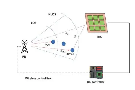
Figure 1.IRS-assisted mmWave downlink WPT system.
whereLis the number of scattering paths in the narrowband mmWave channel,αldenotes the fading coeffciient of thelth path,which is usually modeled as a complex Gaussian distribution.andis the array response vector of the antenna array at the transmitter end of thelth path.ϕlandϑla(ϑle)denotes the deviation Angle and azimuth Angle(depression Angle)of thelth path at the transmitting end,which are generally considered to be uniformly distributed in [0,2π].Since the receiver is a sensor device with a single antenna,the antenna array response vector at the receiver is not considered.Then the PB-IRS channel is modeled as follows:
Each reflecting unit on the IRS can be viewed as individual physical elements that combine all received signals and then rescatter the combined signals by a certain amount of phase shift.Θ=denotes the matrix of diagonal reflection coeffciients at IRS,where the phase shift and amplitude reflection coeffciients associated with themth passive reflection unit of IRS can be expressed asθm ∈[0,2π],βm ∈[0,1],respectively.Letθ≜[θ1θ2...θm]and suppose thatβm=1,∀m.Next,ωi ∈CN×1andvj ∈CN×1are defnied as the precoding vectors generated by PB for theith DL and thejth DNL,respectively.The different charging rights of the device are denoted byEandE ≥0.The higher the value ofE,the more energy is needed.The link status of the node is judged based on the location of the node device from the base station.Devices in the LOS link state can directly collect energy from the carrying signal transmitted by the PB,while distant or occluded node devices will be in the NLOS link state and need to obtain an additional virtual link with the help of IRS relay.Therefore,the weighted sum power received by the device is:
2.2 mmWave Path Loss Model
In the mmWave transmission scenario,each link between the sender and the receiver is susceptible to blockages in buildings.This section introduces the widely used three-state blocking models:LOS,NLOS,and OUT [27].Specifcially,1) When there is no block between the transmitter and receiver,the link is in LOS state;2) If the link is blocked,the link is in NLOS state.3) If the congestion is too severe,the link cannot be established and the link is in the OUT state.Assume that the length of the transmitter and receiver link isr,then the probabilities in the LOS,NLOS and OUT states are respectively
whereg(·)represents the unit step function,rLis the radius of the LOS stadia region,rNrepresents the radius of the boundary between the NLOS non-line-ofsight region and the OUT region.The values forrLandrNdepend on the propagation scenario and millimeter wave carrier frequency.Measurements have shown that millimeter wave links experience different channel conditions in LOS,NLOS and OUT states.Therefore,this paper adopts a multi-slope path loss model [28].The link path loss models under three states with a propagation distance ofrare shown as follows:
where the lower limit ofrin the frist condition is set to 1,in order to avoid the singularity ofr →0.αLrepresents the path loss index of the link in the LOS state.αNrepresents the path loss index of the link in the NLOS state(2≤αL ≤αN).The unit path losses(that is,path losses at distances of 1m) of LOS and NLOS links areβLandβN,respectively.It is assumed that the path loss of the link in the OUT state is inf-i nite.The constantis added to maintain continuity in the path loss model.
2.3 IRS Assisted mmWave WPCN System Model
As shown in Figure 2,we consider an IRS-assisted mmWave WPCN system consisting of a BS with a transmit antenna,an IRS with a reflection unit,and a single-antenna sensor device.IRS passive components are not on the same plane as BS arrays.All sensor devices judge whether the millimeter-wave communication link is line-of-sight or non-line-of-sight state according to the device location and surrounding conditions,and establish LOS and NLOS clusters.Each cluster contains a cluster head and several cluster members,and a device node can only belong to one cluster.In the uplink WIT,the cluster member sends the collected data information to the cluster head,and then the cluster head node processes and fuses the data information,and directly sends the fused data to the BS.The specifci clustering algorithm adopts the improved LEACH protocol,and the details will be introduced in Section 2.4.To facilitate implementation,it is assumed that the total transmission time of a BS cycle is T,and the BS performs WPT of downlink and WIT of uplink on sensor devices with the assistance of IRS.Specifcially,the WPCN system works in the collect before sending mode,that is,the sensor device frist obtains energy from the signal transmitted by the BS in the downlink,and then uses the obtained energy to maintain its own circuit operation,and transmits its own information to the cluster head node or BS in the uplink.Assume that all channels have uplink and downlink channel reciprocity,following a quasistatic flat fading model that remains constant during each transmission cycle but may vary across transmission cycles.In practice,usually IRS may not be able to undertake complex computational tasks due to its limited computational power.Therefore,this paper assumes that the BS is responsible for executing the optimization algorithm,and then feeds its optimized phase shift vector back to the IRS,so that the IRS can set different reflection paths with the time changes of the two stages of downlink WPT and uplink WIT,namely IRS dynamic beamforming.Considering the current antenna hardware technology,the actual transmitter area can be relatively small,this paper believes that the WPT system will not be affected by path loss and near and far effect too much.

Figure 2.IRS-assisted mmWave WPCN system.
The overall execution process of the system is divided into three stages: WPT phase,WIT I phase and WIT II phase,as shown in Figure 3.

Figure 3.System time allocation diagram.
1)WPT phase:
BS wirelessly transmits energy to all sensor devices,and IRS is used to assist the charging of devices in NLOS link.IRS can help avoid node sleep and data transmission interruption caused by uneven energy consumption(which may be caused by large energy consumption of cluster head nodes/different sensing tasks of nodes).So it assists in reducing the outage probability,and improving weighted reception and power.The duration of this phase ist1.
In this process,it is assumed that the channel state information is known at BS and IRS.The specifci channel estimation process is as follows:when the device sends a status signal,both BS and IRS execute the channel estimation algorithm to obtain the CSI between BS-devices and IRS-devices.In each period T,BS frist sends a pilot signal,IRS performs a channel estimation algorithm to obtain the CSI of BS-IRS,and at the end of each period T,BS sends the obtained CSI information about the channel between BS-devices to IRS via a dedicated wireless control link.Through the above interactive process,the CSI of all links can be obtained by IRS and BS.
2)WIT I phase:
Based on the improved LEACH protocol,LOS and NLOS clusters are formed.All cluster member devices send sensing data to cluster head nodes in TDMA mode.Because the transmission distance in the cluster is short,IRS is not required to assist in this stage to reduce the complexity of system execution.The length of this phase ist2.
3)WIT II phase:
LOS cluster head nodes can communicate directly with BS,while NLOS cluster head nodes are assisted by IRS to transmit to BS to enhance the communication quality because the communication link of mmWave is blocked.The transmission time of LOS class and NLOS class cluster head node ist31andt32,respectively.
2.4 Improved LEACH Protocol
In order to minimize the energy consumption of sensor devices,the uplink information transmission mode of sensor devices adopts the improved LEACH clustering protocol.Traditional LEACH is a low-power adaptive cluster routing protocol [29],which is used for data transmission in wireless sensor networks.The LEACH protocol organizes sensor nodes into clusters,in which the data collected by sensor nodes are transmitted to the cluster head for information fusion,and the cluster nodes send the fused data to the base station.In each round of the LEACH algorithm,a random algorithm is used to determine whether a node in each cluster will become a cluster head.As shown in Figure 4,the LEACH protocol consists of multiple cycles,each cycle includes a cluster building phase and a data collection phase.
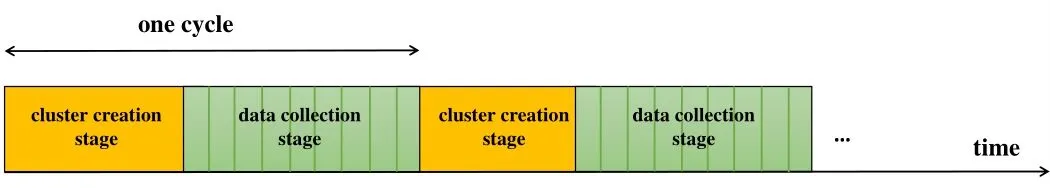
Figure 4.Schematic of the traditional LEACH protocol.
The improved LEACH protocol modifeis the threshold in the traditional cluster head selection algorithm and optimizes the cluster head selection strategy,considering the influence of two factors on cluster head selection:
1) Considering the blocking problem of mmWave communication,the cluster head far away from the BS also needs to have a good LOS state of the link,and the cluster head in the NLOS link state needs IRS assistance.
2)Combined with the energy harvesting level of the node itself.Better line-of-sight state and higher residual energy of the link are considered to select the appropriate cluster head node.
The cluster head selection threshold of theith node is given by:
whereqis the expected percentage of cluster heads,uis the path loss.ris the number of cycles.Gis a collection of nodes that have not been cluster heads in the last 1/qrounds.Emaxis the maximum energy storage capacity of a node.are the current remaining energy and collected energy of theith node,respectively.Each node is initialized to a random number,and the random values of all nodes that are not selected as cluster heads are compared with the thresholdTi.If the value is less than or equal to the threshold,the node is selected as the cluster head.
The detailed cluster head selection algorithm is shown in Figure 5.The detailed execution process is as follows:


Figure 5.Flow chart of cluster head node selection algorithm of improved LEACH protocol.
III.PROBLEM FORMULATION
In this section,we formulate the system charging and data propagation problems,which aim at maximizing the minimum system spectral effciiency.
Based on the above system modeling,combining the downlink WPT and uplink WIT,the harvested energy is used as the power supply for the node to transmit data information,and the uplink information transmission power of the node is given.Clusters are established according to the modifeid clustering algorithm,and the two types of cluster head nodes receive the messages of all cluster member nodes and forward them to the base station.The energy consumption of cluster member node is mainly consumed in sending data to cluster head node,while the energy consumption of cluster head node mainly includes receiving data from cluster member node,data fusion of signal and data transmission to BS.Among them,IRS enhances the gain of receiving carried signals in the WPT stage,and assists the information transmission of non-line-of-sight link state nodes in the WIT stage.Next,we model the problem in stages:
1) WPT phase: BS wirelessly transmits energy to all sensor devices,and uses IRS to assist the charging of devices in NLOS link.The diagonal reflection coeffciient matrix at IRS for auxiliary downlink WPT is defnied asΘ1=where the phase shift and amplitude reflection coeff-i cients associated with themth passive reflection unit of IRS are denoted asθ1,m ∈[0,2π]andβ1,m ∈[0,1],respectively.We defnie thatθ1≜[θ1,1,θ1,2,...,θ1,M]andn the same way,Θ2=is the diagonal reflection coeffciient matrix at IRS when assisting the uplink WIT,where the phase shift and amplitude reflection coeffciients associated with themth passive reflection unit of IRS can be expressed asθ2,m ∈[0,2π] andβ2,m ∈[0,1],respectively.We defnieθ2≜ [θ2,1,θ2,2,...,θ2,M],and assume thatdenotes the channel from BS to theith DL,is defnied as the channel from BS to thejth DNL,denotes the channel from IRS to thejth DNL,andG ∈CM×Nis the channel from BS to IRS.The transmit precoding vectors of the BS for LOS and NLOS clusters aref1∈CN×1andf2∈CN×1,and we defnieF=[f1,f2].Then the received power of the ith LOS device isand the collected energy is:
whereηis the undetermined coeffciient.The received power of thejth NLOS device isPr,j=and the collected energy is:
2) WIT I phase:We defnie thatEtrans,Eelec,Eharv,Edataare the energy required by nodes to transmit information,the energy required to maintain circuit operation,the collected energy and the data processing energy,respectively.Then the total energy consumed by thekth device isThe energy owned by member devicekis,and the energy consumption constraint of member devicekin thelth cluster is:
In practice,the energy required by the device to maintain the operation of the circuit is small and constant compared with other energy consumption,so,∀k,∀lis ignored in the simplifeid model here.Furthermore,(10)can be expressed as follows:
Each cluster member device sends its collected data to the cluster head node.The transmit power isPk,l,and the duration isτk,l,thenwhereKlis the total number of member devices in thelth cluster.Furthermore,the reachable sum rate(in bits/Hz)from the cluster member device to the cluster head can be expressed as:
wheregk,l ∈C is the channel gain from the cluster member device to the cluster head.l=1 is the cluster created by the device in the LOS state,andl=2 denotes the cluster created by the device in the NLOS state.N0represents the independent Gaussian noise power of the receiver.
3)WIT II phase: The cluster head node frist aggregates the received data before sending it to the BS,and the IRS assists the cluster head node transmission in the NLOS area,adopting TDMA mode.α1d ∈CN×1is defnied as the channel gain from the cluster head node in the LOS link to the BS,α2d ∈CN×1denotes the channel gain from the cluster head node in the NLOS link to the BS,andα2r ∈CM×1is its channel gain to the IRS.The total energy consumed by the cluster head node isl=1,2.The amount of data received by cluster head nodes in LOS link and NLOS link isBRsum,1andBRsum,2,respectively.If the unit energy consumption of cluster head node processing data is assumed to beeb(inJ/(bits/Hz)),thenl=1,2.Assuming that the unit energy consumption of the cluster head node to successfully transmit data to the BS isep(inJ/(bits/Hz)),thenep·Rsum l,l=1,2.The energy constraint of cluster head node can be obtained as follows:
According to the above model,the minimum spectral effciiency of the system is maximized by jointly optimizing active and passive beamforming(i.e.,precoding vector at BS and IRS reflection phase shift matrix),node transmit power,and uplink and downlink transmission time.We defnie that:t=[t1,t2,t31,t32].We defniePmaxas the maximum harvested power by the nodes.The problem is formulated as follows:
Here,the constraints are explained as follows:In problem (P3),(16) limits the transmit power of the base station to not exceed its maximum rated powerPP,and (17) and (18) are energy causal constraints for cluster devices,which ensure that each device does not consume more energy for WIT than its total energy collected during WPT.Similarly,(19) and (20)are energy causal constraints of cluster head node devices.(23) and (24) are the dynamic IRS passive beamforming constraints of WPT and WIT stages,respectively.(25),(26) and (27) are the total time constraint,nonnegative constraint and node transmit power constraint of the optimization variables,respectively.By disassembling and analyzing the problem(P3),it can be found that the diffciulties in solving the problem mainly lie in the high coupling degree of optimization variables,the large number of constraints and the existence of non-convex constraints.The constraints(19),(20),(23)and(24)are all non-convex,so(P3)is a complex non-convex problem and cannot be solved directly.
IV.JOINT SOLUTION ALGORITHM BASED ON ALTERNATING OPTIMIZATION(AO)
In order to solve the complex non-convex problem established above,a joint solution algorithm based on AO is proposed in this section.Specifcially,v2with the lowest coupling degree is frist solved,then the AO method is used to solve the problems corresponding to different optimization variable sets alternately.We can observe that in problem(P3),v2only involves the objective function and is not coupled with other optimization variables except for the unitary mode reflection phase shift constraint.This means thatv2is separable in (P3),indicating that the optimalv2can be obtained by solving the subproblem independently,and the subproblem only has one phase shift vector.By ignoring the constant term,the optimal solution ofv2can be obtained by solving the following problem:
In problem (P4-2),the objective function is jointly concave with respect to{Pk,1},{Pk,2},tbecause its corresponding Hessian matrix is semi-negative def-i nite and the constraints (38) (39) (40) (41) are convex with respect to{Pk,1},{Pk,2},{γk,1},{γk,2}.However,constraints (23) are not affnie,but we can use the alternate optimization method to updatev1and other optimization variables iteratively.Specifically,for fxiedF1,F2,{Pk,1},{Pk,2},t,{γk,1},{γk,2}.We defnie thatin whichTherefore,the unit mode constraint (23) of IRS reflection phase shift becomes as fol lows:
By relaxing the rank-one constraint (43),(P4-2) can be transformed into a convex optimization problem,which can be solved using existing convex optimization solvers such as CVX.This relaxation of the rankone constraint helps to obtain an upper bound for evaluating the performance loss of other suboptimal algorithms.

To sum up,the specifci pseudo-code implementation of solving problem(P3)is given in Algorithm 2.Firstly,the parameters are initialized andv2is calculated.Then we give the initialization point ofv1,and solve the problem (P4-2) with givenv1.Then,given the remaining optimization variablesF1,F2,{Pk,1},{Pk,2},t,{γk,1},{γk,2},v1is solved by relaxing the rank-one constraint.Finally,the convergence and stopping conditions are judged and the next update iteration is entered.
V.SIMULATION RESULTS AND DISCUSSIONS
To show the feasibility of the improved LEACH algorithm,it is assumed that the node number is 100,the LOS area radius is 50 meters,NLOS region and the OUT region boundary radius of 100 meters.Then,according to the above improved cluster head node selection algorithm,a more intuitive clustering diagram is simulated.As shown in Figure 6,it can be observed that the points labeled 5 and 10 in the fgiure represent the cluster head nodes of the LOS class and the cluster head nodes of the NLOS class,respectively.
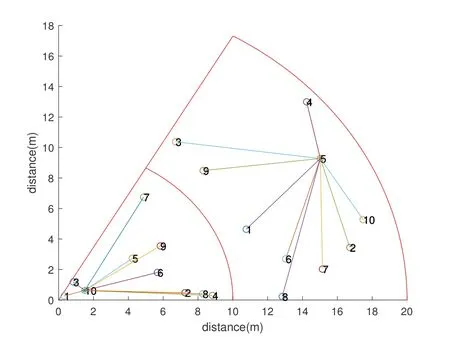
Figure 6.The clustering diagram of the improved cluster head selection algorithm.
In this paper,we verify the performance of the joint optimization strategy of downlink WPT and uplink WIT and the joint solution algorithm based on AO in the IRS-assisted mmWave WPCN system proposed in this section through simulation.In the simulation system,the positions of BS and IRS are set as (0,0,0)m and(10,0,4)m,respectively,and the sensor devices are randomly and uniformly distributed within a 3m radius centered at (10,0,0)m [31].Unless otherwise stated,the default values of relevant parameters in the whole simulation process refer to Table 1:

Table 1.Parameter setting in simulation and experiment.
Based on the above parameter settings,the scheme proposed in this paper is considered to be compared and analyzed with the other two benchmark schemes:
I) IRS dynamic beamforming scheme: by jointly optimizing energy and information transmission,IRS confgiures different reflection phase shift vectors in downlink WPT and uplink WIT,which are represented by(IRS dynamic beamforming).
II) Static IRS beamforming scheme: In this case,IRS is not allowed to reconfgiure its reflection phase shift vectors in uplink WIT,so the IRS phase shift vectors confgiured in uplink WIT and downlink WPT are the same and represented by(IRS static beamforming).
III) Without IRS assistance,denoted by (WithoutIRS).
Algorithm 2.End of iteration identifier.
Figure 7 shows the relationship between the energy harvesting power and the distance from the base station to the IRS reflector.As can be seen from the fgiure,the performance of the conventional system without IRS assistance is much lower than the case with IRS assistance,indicating the necessity of IRS deployment,that is,the additional links generated through IRS can signifciantly enhance the weighted sum power of the device.In addition,the IRS is able to create a ‘signal hot zone’ in its vicinity: that is,higher weighted sum power can be obtained when the IRS is placed at the junction of the LOS and NLOS regions.
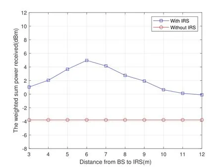
Figure 7.The relationship between the energy harvesting power and the distance from the base station to the IRS reflector.
Figure 8 shows the effect of the BS maximum transmit power on the weighted sum power received by the device.It can be observed that the weighted sum power received by the device with IRS assistance is signifciantly increased.

Figure 8.The relationship between the weighted sum power received and the maximum transmitting power of BS.
Figure 9 shows the relationship between the maximizing minimum spectral effciiency of the system and the transmitted power of BS.It can be observed that,compared with the case without IRS assistance,the design scheme with IRS can signifciantly improve the maximizing minimum spectral effciiency of the system,and the performance improves with the increase of the transmit power of the base station.This is because the effciiency of both downlink WPT and uplink WIT can be improved by utilizing the IRS’s intelligent reflection.In addition,it can be observed from the fgiure that the IRS dynamic beamforming scheme is signifciantly better than the IRS static beamforming scheme in performance improvement.On the one hand,it proves the feasibility of the joint optimization strategy proposed in this chapter and the effectiveness of the proposed algorithm.On the other hand,it is also shown that the IRS static beamforming scheme is not more flexible to reconfgiure the channel because it uses the same phase shift vector for multiple devices in downlink WPT and uplink WIT.Therefore,IRS dynamic beamforming scheme is more suitable for multi-device scenarios.
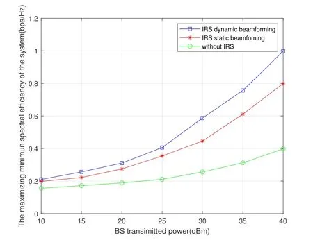
Figure 9.The relationship between the maximizing minimum spectral efficiency of the system and the BS transmit power.
Figure 10 plots the maximizing minimum spectral effciiency of the system against the number of IRS reflection units.Firstly,it can be observed that under the joint optimization strategy proposed in this chapter,the maximizing minimum spectral effciiency of IRS-assisted WPCN system increases with the increase of the number of IRS reflection units.In addition,the performance gap between the IRS dynamic beamforming scheme and the IRS static beamforming scheme becomes larger as the number of IRS reflection units increases.This is because the use of the same phase shift vector in downlink WPT and uplink WIT limits the improvement of IRS passive beamforming gain on system performance,especially when the number of IRS reflection units is large.Therefore,it also indicates to some extent that joint optimization of large IRS-assisted WPCN systems with more reflection units is necessary.
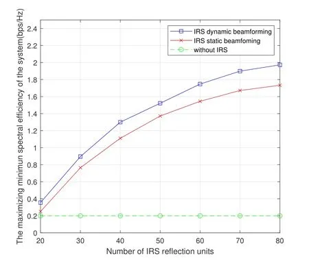
Figure 10.The relationship between the maximizing minimum spectral efficiency of the system and the number of IRS reflection units.
A fundamental problem that exists in WPCN is the well-known ‘double near-far’ phenomenon,in which a device far away from the BS collects less energy in the downlink WPT,but consumes more energy when transmitting information in the uplink WIT than that close to the BS.As a result,the spectral effciiency of distant devices may be signifciantly lower than that of nearby devices,resulting in serious user inequity problems in WPCN.Proper deployment of IRS can alleviate the above situation well.In order to verify the‘double near-far’problem,the system model is simplifeid and it is assumed that there are only two devices in the WPCN system.The position of BS is at(0,0,0)m,device R1 is near to the BS,and device R2 is far away from the BS.Figure 11 shows the relationship between the spectral effciiency of the two devices with and without IRS assistance as a function of the horizontal position of IRS,where the position of IRS is set as(x,0,0)m,and the horizontal axis represents the horizontal position coordinate x of IRS.It can be observed that if IRS is deployed on the side near the BS,the devices in the nearby area have better performance,but the spectrum effciiency of distant devices is very low,resulting in serious user inequity.As IRS moves away from the BS end,the spectral effciiency of distant devices can be signifciantly improved,although the spectral effciiency of nearby devices decreases.Therefore,by deploying IRS in a reasonable location,the ‘double near-far’phenomenon can be mitigated,so that the spectral effciiency of nearby and distant devices can be well compromised.In addition,both of them have signifciant performance improvements compared to the case without IRS,because IRS can effectively compensate for more path loss of devices far away from the BS than nearby devices,helping to solve the user unfairness problem caused by the‘double near-far’phenomenon.
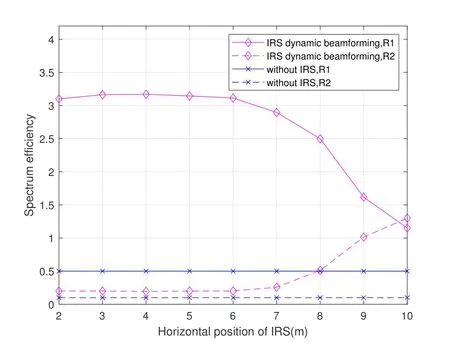
Figure 11.The relationship between system spectral efficiency and IRS horizontal position x.
VI.CONCLUSION
This paper discusses the application of IRS combined with mmWave in wireless energy transmission and wireless power communication network.Firstly,we design the optimization strategy by constructing the system model and problem,combining the mmWave communication and the improved LEACH clustering algorithm considering the influence of energy consumption.Second,we maximize minimum system spectrum effciiency by combining optimization of device transmission power,system time resource allocation and IRS dynamic beamforming.Thirdly,we propose a joint solution algorithm based on AO for the multi-variable coupled non-convex problem.The results show that compared with the benchmark scheme,the proposed scheme and algorithm can signifciantly improve the spectral effciiency of the system.
ACKNOWLEDGEMENT
The work of this paper was supported by the National Natural Science Foundation of China 62001051.
杂志排行

China Communications的其它文章
- Distributed Application Addressing in 6G Network
- A Support Data-Based Core-Set Selection Method for Signal Recognition
- Actor-Critic-Based UAV-Assisted Data Collection in the Wireless Sensor Network
- Integrated Clustering and Routing Design and Triangle Path Optimization for UAV-Assisted Wireless Sensor Networks
- Joint Task Allocation and Resource Optimization for Blockchain Enabled Collaborative Edge Computing
- Stochastic Gradient Compression for Federated Learning over Wireless Network