Oxidation of Fe-Cr-Ni Alloys in a Low Oxygen Partial Pressure Atmosphere to Mitigate Coke Formation
2023-10-23WangHongxiaWangGuoqingZhangLijunWangShenxiangJiaJingshengCuiLishan
Wang Hongxia; Wang Guoqing; Zhang Lijun; Wang Shenxiang;Jia Jingsheng; Cui Lishan
(1. Sinopec (Beijing) Research Institute of Chemical Industry Co., Ltd., Beijing 100013, China;2. Departments of Materials Science and Engineering, China University of Petroleum, Beijing 102249, China)
Abstract: Anti-coking oxide films were prepared on a 25Cr35Ni and 35Cr45Ni alloy surface under the low oxygen partial pressure atmosphere of a H2-H2O mixture. The composition and phase structure of the oxide films were analyzed by energy dispersive spectroscopy (EDS), X-ray diffraction (XRD), and X-ray photoelectron spectroscopy (XPS). The anti-coking performance of a mini tube made of a HP40 (25Cr35Ni) alloy was evaluated on a bench scale pyrolysis and coking test unit.The results showed that the surface Fe and Ni content decreased after the oxidation of the two alloys in a low oxygen partial pressure atmosphere. The oxide films were mainly composed of MnCr2O4 and Cr2O3. The average mass of coke in the mini tube with oxide film decreased by 87% relative to that of a tube without an oxide film when the cracking temperature was 900 °C. The ethylene, propylene, and butadiene yields in the pyrolysis tests were almost the same for the mini tubes with and without an oxide film. The oxide film on the alloy surface effectively inhibited catalytic filamentous coke formation.An industrial test showed that the run length of the cracking furnace with the in-situ coating technology was significantly extended.
Key words: Fe-Cr-Ni alloy; low oxygen partial pressure; oxide film; anti-coking; ethylene cracking furnace; in-situ coating
1 Introduction
The thermal cracking of hydrocarbons is the most important source of olefins, but coke formation by undesired side reactions reduces product yields, increases energy consumption, and shortens the coil service life.The furnace must be periodically stopped and the coke has to be burnt off by means of a mixture of steam and air.Regular decoking operations reduce the onstream time,and therefore the production capacity. Ethylene producers are constantly seeking methods to reduce coke formation and extend the time between decoking cycles.
Coke formation in the coils and transfer-line exchangers of ethylene furnaces is linked to complex mechanisms involving catalytic, radical, and condensation reactions[1].The catalytic mechanism involves metallic species on the internal surface of the cracking coil, i.e., iron (Fe)and nickel (Ni), which potentially have a catalytic activity. Filamentous coke is formed with metallic agglomerates at the propagating tips. The free-radical mechanism involves reactions of micro species, mainly gaseous free radicals, with the macro radicals present at the coke surface. The condensation mechanism occurs at the metallic surface or the coke surface. The heavy polynuclear compounds present in tar and soot condense at the interface, particularly in the quench section where they dehydrogenate and contribute to coke deposition.Thermal cracking furnaces are constructed from heatresistant Fe-Cr-Ni alloys. An inherent and long-standing problem associated with these alloys is their tendency to promote the deposition of catalytic filamentous coke. The main reason for coke deposition in the radiant section of thermal cracking furnaces is the formation of catalytic filamentous coke. Many attempts have been made to establish methods that can effectively suppress coke formation. In summary, the following methods have been proposed:
1) Using alloys that produce less coke. It has been found that increasing the content of chromium (Cr), silicon (Si),and aluminum (Al) in alloys can effectively reduce coke formation[2-3]. However, the increase in the content of Cr,Si, and Al is restricted by their negative impact on the mechanical properties.
2) Application of anti-coking additives.The most commonly used additive for the suppression of coke deposition is dimethyl disulfide (DMDS). In addition to sulfur-containing compounds, the proposed additives mainly include phosphorus-containing compounds[4],silicon-containing compounds[5], tin and antimony-based additives[6], and alkali and alkaline-based additives[7]. The disadvantage of anti-coking additives is that additional injecting apparatus is needed and the additives may have an adverse effect on the down-stream system or environment.
3) Coating of the alloy surface. One of the most effective methods for mitigating coke formation in pyrolysis furnaces is the formation of stable and protective layers in the internal surfaces of coils to deter catalytic coke formation. There are two means to form such protective layers. One is the formation of protective layers enriched in Si, Al, Cr, or other elements by means of thermal spraying, thermal sputtering, high-temperature sintering, or chemical vapor deposition. Companies using these methods include Surface Engineered Products Corporation[8]in Canada, SK Corporation[9]in Korea,and Alon Inc[10]in the United States. The other option is the formation of an in-situ oxide layer in the internal surface of the coils using a special atmospheric treatment at certain temperature. Purdue University[11-12]in United States and Nova Chemicals (International) SA[13-14]in Canada are pioneers in this field.
The in-situ coating technology has shown an excellent performance in the field of coke inhibition in pyrolysis furnaces. The in-situ coating technology requires a special atmosphere to form an anti-coking oxide film on the internal surface of the coils. The adhesion between the oxide film and the coil substrate is firm because the composition of the oxide film is derived from the coil substrate itself. The oxide film is able to effectively isolate the cracking feedstock and internal surface of the coils, and therefore significantly reduces coke formation in pyrolysis furnaces.Based on same mechanism, the SINOPEC (Beijing)Research Institute of Chemical Industry Co., Ltd. (BRICI)and China University of Petroleum (Beijing) have jointly developed an anti-coking technology with an in-situ coating[15-22]. This technology has been applied in 22 cracking furnaces for seven different ethylene producers.The running cycle of these cracking furnaces has been extended to different extents.
The coils in the radiation section of the industrial cracking furnaces mainly consist of 25Cr35Ni and 35Cr45Ni alloys. Anti-coking oxide films were prepared on the 25Cr35Ni and 35Cr45Ni alloy surface under the low oxygen partial pressure atmosphere of a H2-H2O mixture in this study. The anti-coking performance of a mini tube made of a HP40 (25Cr35Ni) alloy was evaluated on a bench scale pyrolysis and coking test unit. The industrial applications of a cracking furnace with the in-situ coating technology were also investigated.
2 Experimental
2.1 Preparation of Fe-Cr-Ni alloy samples before oxidation
The Fe-Cr-Ni alloys used were 25Cr35Ni and 35Cr45Ni centrifugally casted alloys for use in a furnace tube. The chemical compositions of two Fe-Cr-Ni alloy samples are shown in Table 1. Rectangular samples (20 × 10 × 2 mm) were cut from the furnace tube by wire cutting. The samples used were ground (and polished) using grit no.100–800 silicon carbide (SiC) abrasive paper in stages.The grinding first reduced the surface roughness and removed the thin surface layer enriched with Fe and Ni.Prior to oxidation, the samples were first washed with acetone, and then with distilled water, and finally were dried.
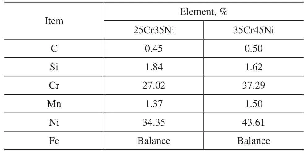
Table 1 Chemical composition of the Fe-Cr-Ni alloy samples
2.2 Oxidation of Fe-Cr-Ni alloy samples
The oxidation test was performed in a thermogravimetric analysis system (Versa Therm HM, Thermo Electron,Newington, MA, USA) in a mixture of H2and H2O at five temperatures varying from 600 to 1000 °C, with three oxidation times varying from 5 to 20 h. The low oxygen partial pressure atmosphere was obtained by passing the high purity H2through deionized water at a flow rate of 50 mL/min.
2.3 Preparation and oxidation of the mini tube
The mini tube was composed of a HP40 (25Cr35Ni) alloy.The chemical composition of the HP40 (25Cr35Ni) alloy is shown in Table 2. The mini tube had an inside diameter of 10 mm and a length of 850 mm. The internal surfaces of the tube were treated by a reamer to remove the oxide scale and reduce the surface roughness to a 1.6 μm finish.The tube was then cleaned with acetone and deionized water before oxidation. The isothermal oxidation tests of the mini tube were performed in a bench scale pyrolysis unit (Figure 1) in a H2-H2O mixture at 900ºC for 20 h.The H2-H2O mixture was obtained by passing the high purity H2through deionized water that was led into the tube from the cross section at a flow rate of 300 mL/min. The ratio of H2to H2O wasV(H2):V(H2O) = 44:1.The heating rate of the tube was 20ºC/min, and the tube cooled naturally in the furnace after the oxidation test.
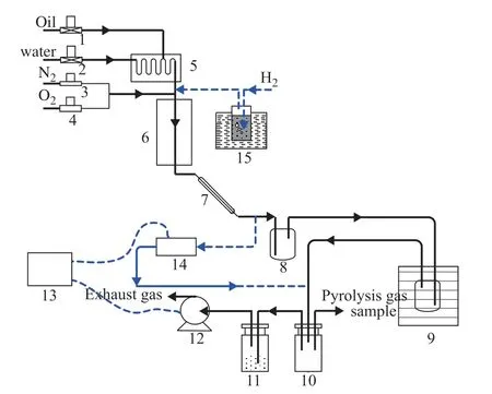
Figure 1 Bench scale pyrolysis and coking test unit
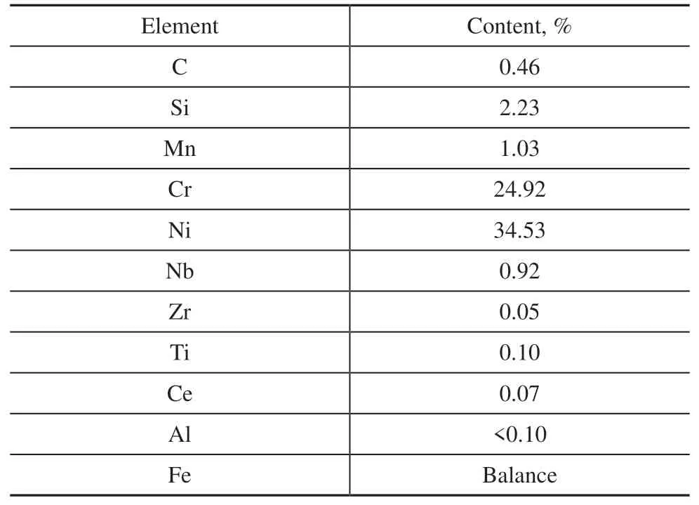
Table 2 Chemical composition of the HP40 (25Cr35Ni) alloy
2.4 Characterization of oxide films
The phases formed in the oxide films were determined by X-ray Diffraction (XRD) (XD-2, Persee, Auburn, CA,USA). The surface composition was analyzed by X-ray photoelectron spectroscopy (XPS) (PHI 5300 ESCA,PerkinElmer, Inc. Waltham, MA, USA). The amounts of Cr, Mn, Fe, and Ni in the oxide films along the depths of the different alloys were analyzed by energy dispersive spectroscopy (EDS) (Link ISIS300, Oxford Instruments,Abingdon, UK).
2.5 Pyrolysis and coking test of the mini tubes
The pyrolysis feedstock in this test was naphtha and its physical properties and group composition are listed in Table 3. The pyrolysis and coking test of the mini tubes was performed in a bench scale pyrolysis unit (Figure 1).The preheater and pyrolysis furnace were heated up at heating rates of 10 °C/min and 20 °C/min, respectively,until the preheater temperature reached 600 °C and the pyrolysis furnace temperature reached 800, 850,and 900 °C for individual test. Water was injected into the preheater at a flow rate of 50 g/h during the rising temperature phase. During the constant temperature phase, naphtha was allowed into the preheater at a flow rate of 100 g/h, while the water flow rate remained at 50 g/h. The naphtha and water were gasified and mixed in the preheater, and then flowed into the pyrolysis furnace tubes to be pyrolyzed. The pyrolysis products from the high temperature tubes passed through the condenser,water cooler, ice cooler, buffer tank, washing tank, wet gas flow meter, and were then emitted. The pyrolysis gas samples were taken from the buffer tank, and their compositions and component concentrations were analyzed by gas chromatography (6890N, Agilent, Santa Clara, CA, USA). The yields of the pyrolysis products were calculated according to the volume, composition,and concentrations of pyrolysis gas, and the mass and properties of feedstock. After the pyrolysis reaction had run for 2 h, the water and naphtha flows were stopped.The temperature of the pyrolysis furnace tubes were cooled to 820 °C, then the tubes were purged with nitrogen gas (N2) at a flow rate of 1 L/min. After purging the tubes for about 15 min, O2was passed into the tubes at a flow rate between 0.1 and 0.3 L/min to burn the coke deposited on the internal surface of the tubes, while the N2flow rate remained unchanged. The CO and CO2concentrations in the decoking off-gas were monitored on line by an infrared gas analyzer (Ultramat 23, Siemens,Munich, Germany). The volume of off-gas was measured by a wet gas flow meter. The concentration and volume data were transferred to a computer, and the mass of the coke deposited on the internal surface of the tubes was calculated.
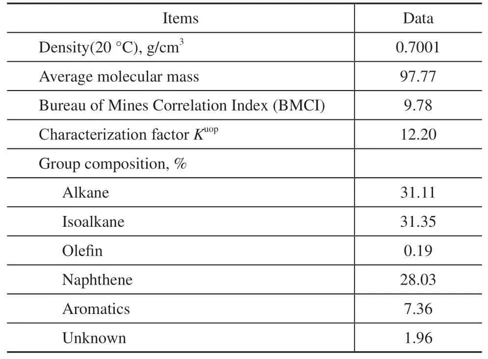
Table 3 Properties and group composition of naphtha
2.6 Testing of the industrial cracking furnace
The anti-coking technology with in-situ coating was applied to the cracking furnace of a domestic ethylene producer with an annual output of 60 kt of ethylene. The operation was compared in the same furnace before and after using this technology, with naphtha as the cracking feedstock and under the same working conditions (Table 4).

Table 4 Working condition of the industrial cracking furnace
3 Results and Discussion
3.1 The effect of oxidation temperature
Oxidation temperature is one of the main factors determining the formation of an oxide film on the surface of the alloys. The 25Cr35Ni and 35Cr45Ni alloy samples were pretreated using a H2-H2O mixture for 10 h at temperatures varying from 600 to 1000 °C.The EDS results were obtained at settings from 10 to 30 kV. The EDS reading, with a given kilovolt for a specific metal, indicated the average concentration of that metal extending from the surface of the samples to a given depth below the surface. These depths have been reported[12]as 0.2, 0.6, 1.1, 1.6, and 2.3 μm for metals at 10, 15, 20, 25, and 30 kV, respectively. The EDS reading for metals at 10 kV was assumed to be the average metal concentration in the 0-0.2 μm layer. The EDS reading for metals at 15 kV was assumed to be the average metal concentration in the 0-0.6 μm layer. This procedure was continued to determine the average metal concentrations in layers with depths up to 2.3 μm.
Figure 2 shows comparisons of the elemental concentration of oxide films on the surface of the different alloys as a function of oxidation temperature. The trends of the Cr, Mn, Fe, and Ni contents in the oxide films on the surface of 25Cr35Ni and 35Cr45Ni alloys at different oxidation temperatures were similar. The Cr and Mn contents in the oxide films on the surface of the two alloys increased as the oxidation temperature increased,while the Fe and Ni contents decreased as the oxidation temperature increased. The total Fe and Ni contents in the oxide films on the surface of the two alloys was still close to 40% after the 800 °C oxidation treatment. Under the same treatment, the total Cr and Mn contents in the oxide films in the surface of the two alloys increased to>50%. The total Fe and Ni contents in the oxide films on the surface of the two alloys reduced to <5% after the 1000 °C oxidation treatment. Under the same treatment,the total Cr and Mn contents in the oxide films on the surface of the two alloys increased to about 90%. The Fe and Ni in the alloys had a strong ability to catalyze coke formation in the high temperature carbonization atmosphere. Enriched Cr and Mn areas and depleted Fe and Ni areas formed in the oxide films on the surface of the alloys in the low oxygen partial pressure atmosphere.These oxide films inhibited the catalytic coke formation on the surface of the alloys in a high temperature carbonization atmosphere.
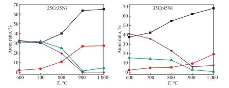
Figure 2 Elemental contents in oxide films as a function of oxidation temperature Reaction conditions: 10 h, V (H2):V (H2O) = 48:1.
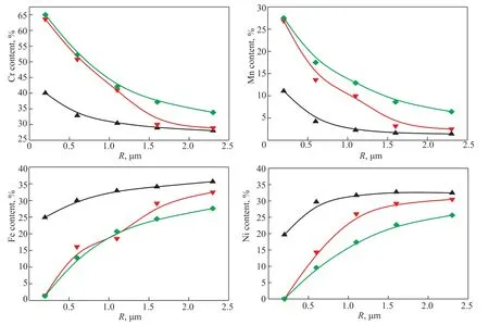
Figure 3 The Cr, Mn, Fe, and Ni contents in oxide films along the surface depth of the 25Cr35Ni alloy Note: the Cr, Mn, Fe, and Ni contents are atomic percentages, 10 h, V (H2):V (H2O) = 48:1.
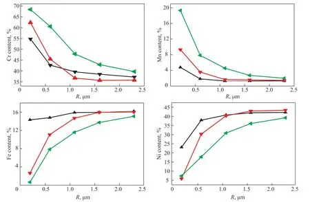
Figure 4 The Cr, Mn, Fe, and Ni contents in oxide films along the surface depth of the 35Cr45Ni alloy Note: the Cr, Mn, Fe, and Ni contents are atomic percentages, 10 h, V (H2):V (H2O) = 48:1.
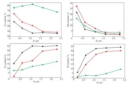
Figure 5 The effect of oxidation time on the Cr, Mn, Fe, and Ni content in the oxide films on the 25Cr35Ni alloy Note: 900 °C, V (H2):V (H2O) = 48:1.
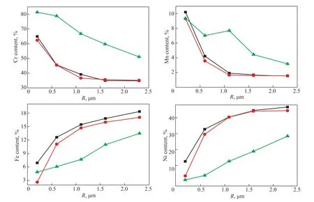
Figure 6 The effect of oxidation time on the Cr, Mn, Fe, and Ni contents in the oxide films on the 35Cr45Ni alloy Note: 900 °C, V (H2):V (H2O) = 48:1.
The Cr, Mn, Fe, and Ni contents versus surface depth for the 25Cr35Ni and 35Cr45Ni alloys at 800, 900, and 1000 °C are shown in Figures 3 and 4, respectively.For each metal in the two alloys, the curves describing this relationship at the different oxidation temperatures had similar shapes and slopes. The enriched Cr and Mn regions on the surface of the two alloys were thickened as the oxidation temperature increased. The Cr content was >45% in the 0-0.6 μm oxide film layer for oxidation temperatures of 900–1000 °C. The Mn content was >10%in the 0-1.0 μm oxide film layer for oxidation temperatures of 900–1000 °C. The depleted Fe and Ni regions on the surface of the two alloys were also thickened as the oxidation temperature increased. The Fe content on the surface of the two alloys was <2% and the Ni content on the surface was almost zero at oxidation temperatures of 900–1000 °C. The depleted Fe and Ni regions were only observed in the 0-0.2 μm oxide film layer. The Fe and Ni contents in the 0.2-1.0 μm oxide film layer were lower than those in the alloy matrix but were still approximately 40%. The oxide film with Cr and Mn enriched areas,and depleted Fe and Ni areas formed on the surface of the two alloys when the oxidation temperature was >900 °C.
3.2 The effect of oxidation time
Oxidation time was another important factor determining the composition of the oxide film on the surface of the alloys. Samples of the 25Cr35Ni and 35Cr45Ni alloys were pretreated using the H2-H2O mixture at 900 °C at times varying from 5 to 20 h. The Cr, Mn, Fe, and Ni contents versus surface depth of the 25Cr35Ni and 35Cr45Ni alloys for 5, 10, and 20 h are shown in Figures 5 and 6, respectively. The trends of the Cr, Mn, Fe, and Ni contents in the oxide films on the surface of the 25Cr35Ni and 35Cr45Ni alloys at different oxidation times were similar. The Cr and Mn contents in the oxide films on the surface of the two alloys increased as the oxidation time was extended, while the Fe and Ni contents in the oxide films on the surface of the two alloys was reduced as the oxidation time was extended. The areas of Cr and Mn enhancement and Fe and Ni depletion on the surface of the two alloys both expanded as the oxidation time increased. These areas formed on the surfaces of the two alloys when the oxidation time was 20 h.
3.3 Analysis of the alloy surface layers by XRD and XPS
The XRD patterns of 25Cr35Ni and 35Cr45Ni alloy samples pretreated using the H2-H2O mixture at different oxidation temperatures are shown in Figure 7. Figure 8 shows the XPS results of the surface composition of the 25Cr35Ni and 35Cr45Ni alloys after the oxidation pretreatment.

Figure 7 The XRD patterns of samples pretreated at different oxidation temperatures
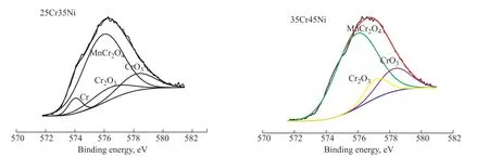
Figure 8 The XPS results of alloy surface composition after oxidation pretreatment
Figures 7 and 8 show that Cr2O3and MnCr2O4were the main oxides on the surface layers of the 25Cr35Ni and 35Cr45Ni alloys oxidized in low oxygen partial pressure atmosphere. No Fe and Ni oxides were found on the surface layers. This phenomenon can be explained according to the theory of alloy oxidation thermodynamics. Figure 9 shows the decomposition pressure of MnO, Cr2O3, NiO, FeO, and H2O according to calculations with thermodynamics data[23]. As shown in Figure 9, MnO and Cr2O3exist stably, while NiO and FeO are not stable when the volume ratio of H2to H2O in a low oxygen partial pressure atmosphere was controlled to be within 2.35–830 (Figure 9 region a). Therefore, no Fe and Ni oxides were found on the surface layers of alloys.Most researchers consider the formation of MnCr2O4to be due to the reaction between Cr2O3and MnO[24-26].It is also speculated that double oxide layers form on the surface of alloys, i.e., an MnCr2O4layer on the top and a Cr2O3layer on the bottom. The thermodynamics calculation and coking test showed that MnCr2O4on the surface layers of alloys was more stable than that of Cr2O3in a high temperature, high carbon potential, and low oxygen partial pressure atmosphere during hydrocarbon pyrolysis. The anti-coking ability of MnCr2O4was better than that of Cr2O3in a carbonization atmosphere[27]. It is likely MnCr2O4catalyzed the coke gasification reaction on the surface of alloys[28]. The presence of an MnCr2O4layer on the surface of alloys helped to improve the anticoking ability of the alloys.
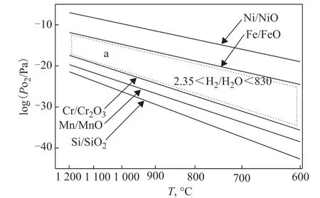
Figure 9 Equilibrium oxygen partial pressures of metal oxides and the H2-H2O gas mixture
3.4 Coking test using the mini tubes
To provide a foundation and basis for industrial experiments and the potential applications of in-situ coating technology, the anti-coking performance of the mini tube was studied on a bench scale pyrolysis and coking test unit controlling the common parameters of industrial cracking furnaces, such as the raw materials,cracking temperature, and water/oil ratio.
Figure 10 shows the mass of coke in a mini tube without an oxide film during five short pyrolysis cycles and the mass of coke in a mini tube with an oxide film during 10 short pyrolysis cycles. It can be seen from Figure 10 that: (1) the mass of coke without an oxide film was relatively stable, with average values of 0.59, 0.70, and 0.91 g at 800, 850, and 900 °C, respectively; and (2) the mass of coke with oxide film displayed an upward trend with increasing coking test time, and the mass of coke increased from 0.08 to 0.23 g and from 0.10 to 0.17 g at 800 and 850 °C, respectively. At 900 °C, the mass of coke was very stable, with an average value of 0.12 g, and the average mass of coke in the mini tube with an oxide film decreased by 87% relative to that of the mini tube without an oxide film.
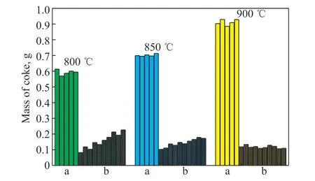
Figure 10 Mass of coke in the mini tube under different pyrolysis temperaturesNote: a: without oxide film; b: with oxide film; feedstock:NAP,2 h, M(water): M(oil) = 0.5.
The ethylene, propylene, and butadiene yields in the naphtha pyrolysis tests in the mini tubes with and without oxidefilms are shown in Table 5. The yields of the main pyrolysis products in the mini tube with oxide film were almost the same as those in the mini tube without oxide film.
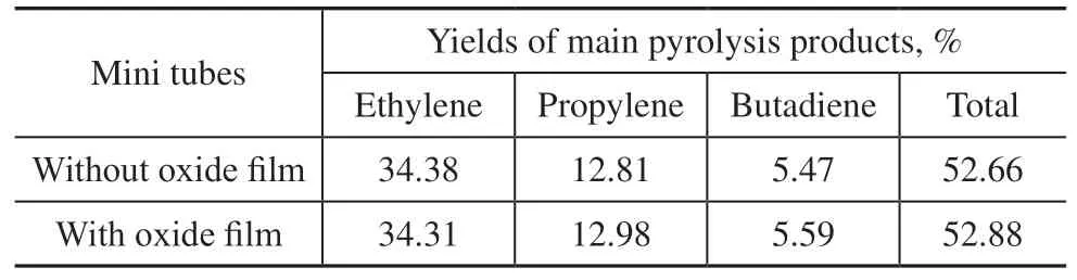
Table 5 Yields of the main pyrolysis products of mini tubes under same pyrolysis conditions
3.5 Test of industrial cracking furnace
The tube metal temperature (TMT) of the radiant section of the cracking furnace is one of the important parameters that restricts the operating period of the cracking furnace.Under relatively stable operating conditions, the change of the TMT in the radiant section can most sensitively reflect the coking condition in the radiant section.
Figure 11 shows the change trend of the maximum TMT of the cracking furnace with and without the in-situ coating under the same cracking conditions versus the running days.
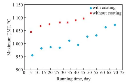
Figure 11 Variation trend and of maximum TMT with running days of the cracking furnace
Figure 11 shows that the maximum TMT of the cracking furnace with the in-situ coating was lower than that of the same furnace without the in-situ coating. The maximum TMT of the cracking furnace without the insitu coating reached almost 1100 °C when it ran for 45 days. In contrast, the maximum TMT of the cracking furnace with the in-situ coating was only slightly higher than 1070 °C when it ran for 69 days. Taking 1100 °C as the TMT limit temperature, the running cycle could reach 96 days according to the change trend of the maximum TMT of the cracking furnace with the in-situ coating. The industrial test showed that the in-situ coating technology effectively suppressed the coking of the furnace tube in the radiation section of the cracking furnace. The running cycle of the cracking furnace was significantly extended.
4 Conclusions
We prepared anti-coking oxide films on 25Cr35Ni and 35Cr45Ni alloy surfaces under the low oxygen partial pressure atmosphere of a H2-H2O mixture. We studied the anti-coking performance of a furnace tube made of a HP40 (25Cr35Ni) alloy on a bench scale pyrolysis and coking test unit. We also investigated the potential for industrial applications. The conclusions were as follows.1) Oxide films with areas of Cr and Mn enrichment and Fe and Ni depletion formed on the surfaces of the 25Cr35Ni and 35Cr45Ni alloys following the pretreatment with the H2-H2O mixture. The Cr and Mn contents in the oxide films on the surface of the two alloys increased, while the Fe and Ni contents reduced as the oxidation treatment temperature increased. The oxide films thickened as the oxidation temperature increased. Oxide films with areas of Cr and Mn enrichment and Fe and Ni depletion formed on the surfaces of the two alloys when the oxidation temperature was >900 °C.
2) The regional enrichment of Cr and Mn and depletion of Fe and Ni on the surfaces of the 25Cr35Ni and 35Cr45Ni alloys were both enhanced as the oxidation time increased. The optimal oxide film enrichment of Cr and Mn and depletion of Fe and Ni occurred when the oxidation time was 20 h.
3) The main oxides in the surface layers of 25Cr35Ni and 35Cr45Ni alloys were Cr2O3and MnCr2O4when the alloys were pretreated under a low oxygen partial pressure atmosphere.
4)In the bench scale pyrolysis and coking test, when the cracking temperature was 900 °C, the mass of coke in the mini tube with an oxide film was stable during 10 short pyrolysis cycles and the average mass of coke decreased by 87% relative to the mini tube without an oxide film.The yields of the main pyrolysis products in the mini tube with an oxide film were almost the same as those in the mini tube without an oxide film.5) The industrial test showed that the in-situ coating technology effectively suppressed the coking of the furnace tube in the radiation section of the cracking furnace. The running cycle of the cracking furnace was significantly extended.
Acknowledgements:This work was supported by the scientific research project of China Petroleum & Chemical Corporation(Grant No. 411048).
杂志排行

中国炼油与石油化工的其它文章
- Ultra-deep Removal of Metal Ions from Coal Tar by Complexation: Experimental Studies and Density Functional Theory Simulations
- A Metal-free Polyimide Photocatalyst for the Oxidation of Amines to Imines
- Effect of CeO2 on Activity of Catalysts CuO/ZnO/Al2O3/CeO2 for Synthesis of Methanol
- C9H10O2:0.5ZnCl2/SG as a High-Efficiency Catalyst for Desulfurization of Model Oil
- Effect of Mixed Dispersants on Suppression of the Gel Effect during Aqueous Adiabatic Terpolymerization of AM, NaAA, and DMC
- Pyrolysis Mechanism of a Cyclotriphosphazene-Based Flame-Retardant Epoxy Resin by ReaxFF Molecular Dynamics