Differences of Polygonal Faults with Irregularly Polygonal Geometries: A Case Study from the Changchang Sag of Qiongdongnan Basin, Northern South China Sea
2023-03-17LIYufengPURenhaiZHANGGongchengandFANXiaowei
LIYufeng, PU Renhai, ZHANG Gongcheng, and FAN Xiaowei
Differences of Polygonal Faults with Irregularly Polygonal Geometries: A Case Study from the Changchang Sag of Qiongdongnan Basin, Northern South China Sea
LIYufeng1), 2), 3), *, PU Renhai2), ZHANG Gongcheng4), and FAN Xiaowei5)
1),,621010,2),,,710069,3),,510075,4),100028,5),,710075,
Polygonal faults (PFs) generally have a classic polygonal geometry in map view. However, under the influence of tectonic faults, diapirs, channels, and slopes, the classic polygonal geometry of PFs is not preserved, demonstrating differences (different characters) in map-view 3D seismic data covering an area of 334km2of the Changchang (CC) sag, are used to document the map- view and cross-sectional characteristics of PFs. These data also help investigate the irregularly polygonal geometries of PFs due to the presence of influence factors, such as transtensional faults, submarine fans, channels, diapirs/gas chimneys, and the basal slope within the lower-middle Miocene strata. Results show that various irregularly polygonal geometries of PFs can be classified into en- echelon and arcuate PFs, channel-segmenting and -bounding PFs, radial PFs, and rectangular PFs in map-view. En-echelon and arcuate PFs are induced by transtensional faults and exhibit a unique ‘flower’ structure in NE- and SE-trending cross-sections in the NW area of the study area. This finding is documented for the first time. Channel-segmenting PFs occur in the (northwest) low-amplitude muddy channel and are inhibited in the (southeast) high-amplitude sandy channel in the SW area. Radial PFs are radially aligned around a gas chimney/diapir containing some high-amplitude anomalies (HAAs) in the middle area. The presence of intrusive sandstones with HAAs along the periphery of the diapirs restricts the occurrence of PFs. Two high-amplitude submarine fans act as a mechanical barrier to the propagation of PFs. Meanwhile, the (moderate) slope in the NE area induces rectangular PFs. Additionally, the geneses of the PFs in the current study are comprehensively discussed. This study adds to our understanding of the differences between PFs with irregularly polygonal geometries.
channel; diapir; genesis; influence factors; northern South China Sea; polygonal fault; slope; transtensional faults
1 Introduction
Polygonal faults (PFs) are pervasively developed over the passive continental margin basins (Cartwright, 2011). These faults are due to layer-bound extensional faulting, wherein the underlying and overlying strata remain undis- turbed; thus, they are also termed layer-bounded faults (Cart- wright and Dewhurst, 1998). PFs are also non-tectonic in origin with the polygonal geometry in plane view (Cartwright and Dewhurst, 1998) and primarily developed in the fine-grained sedimentary sequences that form during theearly burial history (Cartwright and Dewhurst, 1998). More- over, PFs serve as a pathway for hydrocarbon expulsion and provide a conduit for hydrocarbon migration (Alrefaee., 2018; Hoffmann., 2019; Li, 2022). They are also used to assess the slope stability of the continental margins (Ireland., 2011). PFs are generally of a basin- scale distribution (>150000km2) (Cartwright and Dewhu- rst, 1998).
Various factors can influence the orientation of realignedPFs that present irregularly polygonal geometries. PFs have a strictly orthogonal geometry relationship with tectonic faults in a region where PFs and tectonic faults border eachother (., in the Sable sub-basin, Canadian Atlantic margin) (Hansen., 2004). PFs also deviate from their polygonal geometries to a remarkably radial geometry array around the salt diapir, mud diapir, and gas chimney (Hansen., 2005; Stewart and Davies, 2006; Sun., 2010; Wang., 2010). Moreover, PFs deform or penetrate the layers overlying buried channels, and their strikes are always perpendicular to the axes of channels (Victor and Moretti, 2006; Cartwright, 2011; Ireland., 2011). In the North Sea Basin (Jackson., 2014) and offshore Uruguay (Turrini, 2017), deepwater slope fan sandstones acted as mechanical barriers and inhibited downwardfault propagation, thereby influencing fault height, interval space, and even strike. Strikes of PFs parallel those of the slope in offshore Mauritania, where PFs are well aligned and antithetic to the bedding dip (Ireland., 2011). In addition, the geometries of PFs change from linear to rectangular and then polygonal for high, moderate, and low or no slope in the Great South Basin, respectively (Li., 2020b). Most PFs developed within the wedge tier tend to dip toward the thin end of the wedge (Cartwright, 2011). Under anisotropic stress conditions, PFs are preferentially oriented parallel to maximum horizontal stress (Ghalayini., 2017; Ho., 2018). Nevertheless, these factors, such as tectonic faults, diapir/gas chimneys, topographic de- pressions, channels, deepwater fans, and slopes, rarely co- exist in a small area where various polygonal fault geometries also coincide.Herein, 3D seismic data covering a small area of Changchang sag provide an excellent opportunity to observe multiple factors influencing the orientation of PFs.
Numerous PFs are widely developed in fine-grained se- diments (vast thick mudstones) of the deepwater area of the northern South China Sea, including the Qiongdongnan Basin (QDNB) and the Pearl River Mouth Basin (PRMB) (Sun., 2014) (Fig.1a). In the western part of QDNB, PFs generally present typically polygonal geometry andsome are radial around mud diapirs and gas chimneys (Sun., 2010; Wang., 2010; Chen., 2011, 2012; Yu., 2011). These PFs are found in two tiers within the upper-middle and upper Miocene strata (Sun., 2010). Meanwhile, some PFs are perpendicular to each other due to the tensile stress field produced by differential settlement (Han., 2016). In the Beijiao sag of the middle QDNB, PFs occur in the upper-middle-lower Miocene strata, and sandy channels strongly affect the geometry of PFs (Li., 2017a; Li., 2022). These PFs do not exhibit a poly- gonal geometry but show the channel-segmenting and -bou- nding faults, which both exhibit a mutually perpendicular geometry. Away from the channels, these PFs gradually show a classic polygonal geometry. In the eastern part of QDNB, tectonic faults and mud diapirs severely affect the geometry of PFs, resulting in minor faults perpendicular to tectonic and radial faults around mud diapirs, respective- ly (Yin., 2010). Mudstone is the dominant lithology of polygonally faulted host strata in the lower-middle Mio- cene layers (Yin., 2010). In the Middle PRMB, PFs present polygonal geometry with a randomly striking di- rection (Yang., 2017). In the eastern PRMB, PFs occur in the middle-lower Miocene strata and present a classic polygonal geometry due to syneresis (Jiang., 2017).

Fig.1 Main structural division of the QDNB and PRMB (modified from Xie et al., 2011; Tian et al., 2015) (a) and the time structure (horizon T40) of the study area (b).
This study aims to understand the influence of the afore- mentioned factors on the geometries of PFs. Distinct geo- metries of PFs are depicted using 3D seismic data from the Changchang sag, eastern QDNB of the northern South China Sea. Factors causing the irregularly polygonal geo- metry of faults are comprehensively investigated. Horizon-tal slices extracted on seismic coherence attributes are usedto detect the various geometries of PFs caused by the inter-play of tectonic fault, diapir/gas chimney, channel, submarine fan, and slope. The root mean square (RMS) attribute identified coarse-grained sandstones in/sourced from the submarine fan and/or channel. Irregularly polygonal geo- metries of PFs affected by various influence factors, such as transtensional faults, submarine fans, channels, diapirs/ gas chimneys, and basal slopes, are extensively studied. The current study focuses on the geometries of PFs affected by (extensional) transtensional faults, channels filled byfine- grained mudstones and coarse-grained sandstones, diapirs, and gas chimneys. In addition, combined geneses of PFs from the CC sag are discussed comprehensively.
2 Geological Setting
The Qiongdongnan Basin (QDNB) is located in the nor- thwestern part of the South China Sea (SCS). This basin is one of the largest passive continental marginal basins in the Western Pacific Ocean (Ru and Pigott, 1986). The mid-dle part of the QDNB bears the Huaguang (HG), Beijiao (BJ), and Changchang (CC) sags (Fig.1a). The CC sag is in the east part of the QDNB (Fig.1a) and the study area dips southwestward (Fig.1b). The QDNB underwent three tectonic evolutionary stages, namely rifting, thermal subsi-dence, and accelerated thermal subsidence (Fig.2), whichelevated the topography in the northern and southern parts; however, the topography of the middle part of the QDNB is low (Xie., 2011; Tian., 2015). The QDNB co- vers approximately 82000km2, with more than 60% of the present-day area under a deepwater environment (Zhang., 2018). The present-day isobath of the 3D seismic survey is from 2410m to 2625m, assuming a 1500ms−1velocity of seawater. In response to tectonic movement, basin fill comprises the following two super-sequences: the lower rift and upper post-rift super-sequences. The two su- per-sequences are separated by an angular unconformity that corresponds to seismic reflection horizon T60 (23.3Myr) (Zhu., 2009; Sun., 2010, 2017; Tian., 2015). Coupled with the three tectonic evolutionary stages,the depositional environment transformed into the following: alluvial to lacustrine, onshore to neritic, and shelf-slope to abyssal environments from Paleocene to recent (Table 1; Liu., 2015; Tian., 2015). Two vast submarine fans on horizons T60 and T52 are also presented in the lower Miocene in the CC sag (Cai, 2017). Herein, two sub- marine fans on horizons T60 and T52 are reported by the previous studies (Cai, 2017; Li., 2021). Drill cores from the CC sag reveal that vast fine-grained mudstones encasing the coarse-grained sandstones are dominantly de- veloped in the deepwater environment in the lower-middle Miocene (Cai, 2017), where PFs occur.
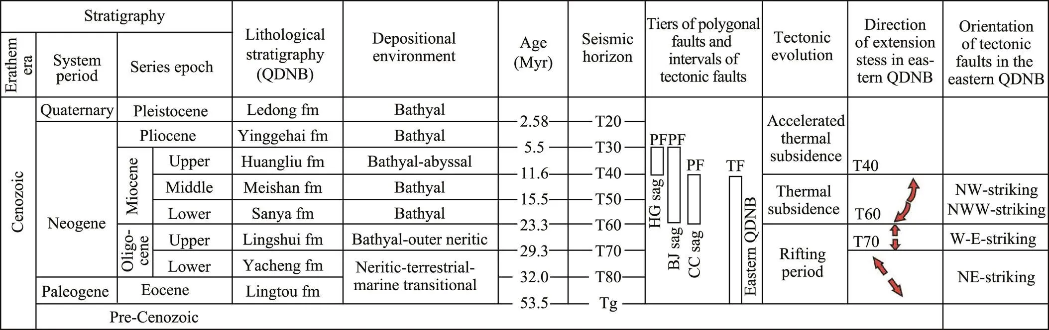
Fig.2 Schematic overview of the major stratigraphic column and tectonic events in the deepwater area of the QDNB since the Palaeocene depositional environment in the deepwater area of the QDNB (Liu et al., 2015; Tian et al., 2015). PFs in the Huaguang (HG) sag (Sun et al., 2010; Wang et al., 2010; Chen et al., 2011), the Beijiao (BJ) sag (Li et al., 2017a), the Changchang (CC) sag (Yin et al., 2010). The direction of extension stress and orientation of tectonic faults in the eastern QDNB (Hu et al., 2013; Zhang et al., 2013; Zhou et al., 2018).
Rifting during the Eocene-to-middle Miocene age produced NE-SW, E-W, and NW-SE trending normal faults in the QDNB (Zhang., 2013; Zhou., 2018). These E-W-trending faults were mainly developed and remained active during the late Oligocene age. By contrast, the rough- ly NW- or WNW-trending faults were dominantly active during the early-middle Miocene age (Fig.2; Zhang., 2013; Zhou., 2018). NW-trending faults always exhibit the ‘flower’ structure shape and transtensional strike- slip activity in the CC sag (Li., 2014). Notably, dextral transtensional (strike-slip) and extensional (normal) faults occur in the western and eastern parts of the CC sag, respectively (Li., 2014). The composite fabric of tectonic faults demonstrates the early extensional and later strike-slip nature of the CC sag (Li., 2020a). Extensional faults formed during the Eocene to early Oligocene age, while transtensional faults formed during the late Oli- gocene to early Miocene age (Li., 2020a).
The tectonic faults of the study area mainly comprise transtensional and extensional normal faults (Fig.3a). Transtensional faults are primarily restricted to the SW area. These faults penetrate upward and gradually die out belowhorizon T40. Moreover, these faults exhibit the classic ne- gative ‘flower’ structure, as transtensional (strike-slip) faultsdescribed by Li. (2014). By contrast, extensional nor- mal faults are mainly confined to the NE area. They are a type of extensional normal fault. Most of these faults do not penetrate the tier (horizons T60 and T40) or disturb the PF tier. The two aforementioned areas are separated by a transition zone of the property of transtensional and exten- sional normal faults in the middle study area.
3 Data and Methods
The 3D seismic dataset has been offered by the China National Offshore Oil Corporation (CNOOC) and covers ap- proximately 334km2. A 3km long steamer with 240 channels was utilized to acquire the seismic data, and a total vo- lume of 8×20inch3tuned air gun was used as the seismic source. Conventional techniques, such as amplitude correction, bandpass filtering, and post-stack time migration, were used to process seismic data; pre-stack data were unavailable in this study. The vertical sampling and shot intervals were 4ms and 25m, respectively. The bin size of the seismic volume is 12.5m×12.5m in the-line and inline directions. The 3D seismic data have a dominant fre- quency of about 40–60Hz. The vertical seismic resolution of the seismic data is about 12m, which is equal to 1/4 of the wavelength at the dominant frequency.
Based on nannofossil biostratigraphy from limited drilling cuttings, isochronous seismic horizons for T70 (29.3 Myr), T60 (23.3Myr), T50 (15.5Myr), T40 (11.6Myr), T30 (5.5Myr), T20 (1.9Myr), and their ages (Myr) are provided by CNOOC (Table 1). The wells, namely YL19- 1-1 and LS33-1-1, are supplemented and used for age ca- librations in the seismic-stratigraphic framework in the deep- water part. Calibrating the ages of seismic horizons older than 29.3Myr (T70) presents some uncertainties due to the lack of well calibration. Constraining horizons below T70 is difficult. The horizons present a stratigraphic frameworkand are sufficient for the identification of PF characteristics.
Seismic attribute maps (such as RMS and coherence) were plotted to identify faults, gas chimneys, and diapirs. The RMS attribute highlights the variation of acoustic impedance within a selected time window (sample interval). A high RMS value corresponds to a large variety of acoustic impedances. Herein, the RMS was used to detect the coarse-grained sandstones of the submarine fans and channels. The seismic coherence attribute was utilized to interpret tectonic faults, PFs, and diapirs (low coherent values) on selected horizons. Fault trace maps from coherence attribute horizontal slices were also demonstrated. The vertical displacement distribution of PFs was obtained by mea- suring the (time) throw versus depth (TWT) of these PFs.
4 Results
4.1 Geological Features of the Strata Containing PFs
Various geological features of the strata containing PFs are mainly confined by horizons T40 and T60. The geomorphology of the study area, Horizon T40, has an overall southwesterly slope (Fig.1b). A NW-trending channel and a part of the NW-trending Central Canyon are located in the SW area. A subcircular anticline with a steep southwestern limb is located in the middle area, with steep west and south sides. A steep southwesterly drop occurs in the NE corner of the study area (Fig.1b). The transtensional (strike-slip) faults (pink), submarine fan on horizon T52 (blue dashed lines), central Canyon, and channels are distributed in the SW of the study area (Fig.3a). Another sub- marine fan on T60, a diapir, and gas chimney is located in the middle area.
4.2 Cross-Sectional Features of the PFs
The polygonal fault tier is mainly confined by horizons T60 and T40, and PFs are dominantly developed within the lower-middle Miocene strata (Fig.3a). This tier gradually thins away from the NE area. The large PFs crosscut the entire vertical extent of the lower-middle Miocene strata in the NE area. The rest of the PFs, particularly those from the middle area, are inhibited in the strata.
The lengths of several PFs are affected by parts of the central canyon and submarine fan on T52 (Fig.3b), a chan- nel and transtensional faults (Fig.3c), and a diapir and gas chimney (Fig.3d). However, only the slope further affects the PFs with the largest throw in the NE area (Fig.3e). A representative selection of-plots (Fig.3f), compiled from these PFs (Figs.3b–e), demonstrates ‘C’- and asymmetric ‘M’-shaped geometries, which are consistent with theclassic throw geometry of PFs (Cartwright, 2011). Throws commonly have a middle maximum, exhibiting either only a sharp peak (III and I within Fig.3f) or a plateau shape (Figs.3e and c). The maximum throws of these faults near the central canyon and a submarine fan (Fig.3b), channel and transtensional faults (Fig.3c), diapir and gas chimney (Fig.3d), and slope (Fig.3e) are approximately 10, 19, 10, and 35ms (Fig.3e), respectively. PFs mapped on the seismic profile are generally planar with dips of approximately56˚, assuming a velocity of 2400ms−1within the tier (based on well YL19-1-1). These PFs gradually decrease upward and downward, with a marked gradient in these throws. A clear trend reveals vertical trace lengths that are proportional to maximum displacements (Fig.3f). In comparison to the large PFs, influenced only by the slope, the rest are relatively small in length and throw (shown in (I). (II), (III), and (IV) of Fig.3f) and influenced by factors, such as the central canyon, channel, diapir, and gas chimney. Various PFs are described below, with emphasis on their spatial and plan-view relationships to the various factors.
4.3 Transtensional and Extensional Normal Faults
Upper transtensional faults in the SW area show classic ‘flower structure’ shapes, while lower transtensional faults are not ascertained due to the limitation of seismic resolution. These transtensional faults penetrate upward into the lower Miocene (T60–T50), where they encounter the PFs (Fig.3a). These transtensional faults also present low coherence attribute values in the upper Oligocene strata, as shown in Fig.4a. These faults exhibit a NW-trending distri- bution and mainly extend 2–15km long (Fig.4a1), while some extend into the upper-lower Miocene (Fig.4b) and middle Miocene (Fig.4c).

Fig.3 (a), Seismic profile showing characteristics of PFs; (b), below the central canyon and submarine fan; (c), below a channel filled by mudstones; (d), near a gas chimney, diaper, and submarine fan; (e), affected only by a slope excluding other influence factors above; (f), diagram of throw (T) vs. depth (z) for various PFs (b–e). (I–IV) of Fig.f are from Figs.b–e, respectively. HAAs mean high amplitude anomalies. See location in Fig.1b.
The vast majority of extensional normal (tectonic) faultsin the NE area do not penetrate the tier (Fig.3a). These faults do not extend upward into the lower Miocene strata. The traces of these approximately E-W trending faults are around 5–10km long (Fig.4a1). However, some faults from the NE part of the map trend NW-SE and have relatively short(2–5km) fault traces (Fig.4a1). In comparison to transten- sional faults in the SW area, these faults are relatively short in cross-sections and do not continue up to deeper levels (Fig.3a).
4.4 Arcuate and En-Echelon PFs in the SW Area
Arcuate (red dashed) PFs occur in the western part of the SW area and are mainly situated between transtensional
faults (distal parts) (Figs.5a, b). Arcuate PFs with lengths of 2–5km from horizon T52 (Fig.5a) are slightly longer than those of 2–3km (Fig.5b). These PFs always laterally extend up to the nearby NW-trending transtensional faults, and the internal spaces between PFs are 0.3–1km. These faults are also at a substantially small angle to the transtensional faults. However, PFs show non-preferential strikes in a small area, where the transtensional faults are rarely distributed (Fig.5b). These PFs have approximately equal numbers of faults dipping in opposite directions (Fig.5c).
En-echelon PFs occur in the eastern part, and their fault traces exhibit an en-echelon geometry (Figs.5a, b). These en-echelon PFs are at a high angle (approximately 70˚) to the transtensional faults. Most PFs are confined between these transtensional faults, and some cross the transtensional faults. The density of en-echelon PFs with an internal spacing of 0.5–2km (Fig.5a) is lower than that with an internal spacing of 0.3–0.5km (Fig.5b). In addition, the number of the en-echelon PFs from horizon T52 (Fig.5a) is less than that of the en-echelon PFs from horizon T50 (Fig.5b).
In addition, the seismic profile (Fig.6a), which is parallel to the transtensional fault, shows that the mutual hanging walls of pairs of conjugate faults are a series of anticlines, between which dish-shaped synclines are distributed. The limbs of anticlines and synclines comprise a set of high- order folds (Fig.6a), as described by Watterson. (2000). Some levels between horizons T50 and T60 bend upward within anticlines, and several levels bend downward withinsynclines (Fig.6a). Each of the anticlines and synclines has nearly equal numbers of PFs dipping in opposite directions. (En-echelon) PFs in each anticline exhibit a classicalnegative flower structure, bending upward in cross-sections. Each anticline shows additional faults in the upper part of the tie and extends the short distance, and a few faults in the lower part almost crosscut the entire tier. The en-echelon PFs comprising the flower structure are still restrained by horizons T60 and T40.
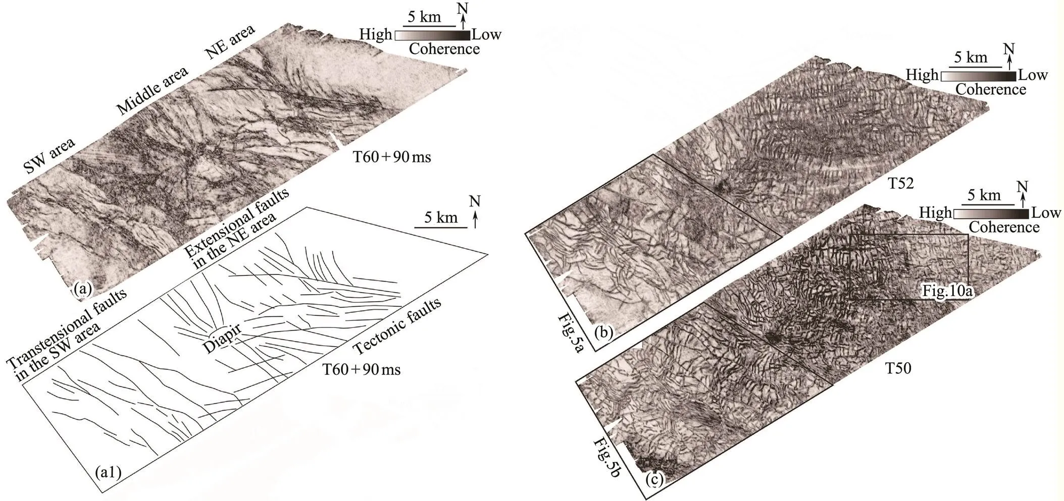
Fig.4 (a), Planform distribution of transtensional and extensional faults from a coherence attribute slice of horizon T60 below (+) 90ms. (a1), a fault-trace map of Fig.3a and a sub-circular diapir in the middle area. (b) and (c), Planform distribution of transtensional and extensional faults and PFs from coherence attribute slices of horizons T52 and T50.

Fig.5 (a) and (b), Transtensional and polygonal fault-trace maps of coherence attribute horizontal (T52, T50) slices in the SW area, respectively. (c), Seismic profile across non-preferential polygonal fault area showing approximately equal numbers of PFs dipping an opposite direction. See locations of (a) and (b) in Figs.4(b) and 4(c), respectively, and location of cross section (c) in Fig.5b.

Fig.6 Seismic profile along and between two long transtensional faults showing that polygonal fault host strata comprise a series of upward bend anticlines and down bend synclines, and PFs exhibit a ‘flower’ structure. (b) and (c) seismic sections across and between two short transtensional faults showing that PFs also have a ‘flower’ structure. These flower-structure PFs are all bounded by horizons T60 and T40. See locations of (a–c) in Fig.5b.
Two clusters of arcuate PFs are distributed along 2–4 km spaced transtensional faults (northwest tip of Figs.5a, b) and 2–3.5km spaced transtensional faults (southwest tip), respectively. These clusters also present classic negative flower structures, and both do not exhibit an anticline shape (Figs.6b, c). They are confined by Horizon T60 and T40 and dip in the opposite direction, some of which can crosscut downward into a submarine fan and into the bottom lower Miocene strata (T52–T60). These findings suggest that arcuate PFs are closely related to the transtensional faults, and the submarine fan does not act as a mechanical barrier to the propagation of these faults.
4.5 Channel-Segmenting and -Bounding PFs Nearby and Within a Channel
The channel is divided into the low-amplitude (muddy) channel (area) on the left and the high-amplitude (sandy)
channel (area) on the right (Figs.7a, a1, b2). The coherenceattribute horizontal slice map of the channel was also select- ed (Fig.7b1). This channel has a relatively high coherencevalue and is 14km long and 1.5km wide. The low-amplitude channel is pervasively faulted and potentially compartmentalized by the channel-segmenting PFs (Fig.7b2). Truncations and onlaps are observed on the sides of this channel (Figs.7c, d, respectively), and its time thickness is up to 120ms.
PFs, parallel and perpendicular to the channel axis, are termed channel-bounding and -segmenting (polygonal) faults,respectively (Victor and Moretti, 2006). Channel-segmen- ting PFs are dominated by parallel to subparallel segments, oriented NE-SW, and spaced 300–500m apart in the low- amplitude channel (gray zone in Fig.7b2). The channel- segmenting faults tend to die out toward the boundaries of the channel. By contrast, the high-amplitude channel (yellow zone) is devoid of channel-segmenting PFs. Additionally, channel-bounding PFs are parallel or subparallel to the channel axis; PFs away from this channel have a trend of slight polygonal geometry.

Fig.7 (a) RMS and (b) coherence attribute horizonal (T50 above (−) 50ms) slices showing variations of amplitude and coherence attributes within the channel in the SW area, respectively. Time window gate of RMS from T50 to T50 above (−) 50 ms. (a1) and (b1) are amplified parts of (a) and (b), respectively. (b2), fault-channel trace interpretation map showing the relationship between PFs, fine-grained (weak amplitude) and coarse-grained (high amplitude) sediments filled within the same channel in plane view. Representative seismic profiles (c) and (d) perpendicular to the weak and high amplitude channel axis, respectively, and (e) seismic profile along the axis of the channel.
PFs in cross-sections are considerably developed withinand surrounding the low-amplitude area of the channel (Figs. 7c, e, respectively). By contrast, PFs are only slightly developed within and surrounding the high-amplitude channel (Figs.7d, e, respectively). These PFs neither occur above nor within the high-amplitude channel (Fig.7e), which is consistent with their plan-view presence (Fig.7b2). In addition, short PFs only occur below the high-amplitude area of the channel.
4.6 PFs Above the Submarine Fan and Below the Central Canyon
A submarine fan is lobe-shaped and characterized by high amplitudes (as suggested by coarse-grained sandstones). This fan gradually becomes relatively weak from NE to SW (Fig.8a), and its average length and width are appro- ximately 20 and 6km, respectively. Excluding this fan, the rest of the area is dominated by low amplitudes indicative of mudstones. This submarine fan on horizon T60 is presented by a moderate-high amplitude reflection event indicative of coarse-grained sandstones (Fig.8a1). The fan is150ms (180m, assuming a velocity of 2400ms−1) thick and gradually thins and dies out rightward. PFs in the left tip are not observed in low amplitudes on/adjacent to the underlying thickest high-amplitude fan (Fig.8a1). Low- amplitude mudstones above this thickest fan support the shortest PFs, demonstrating that the thickness of the tier thins and is mainly constrained by horizons T50 and T52 (Fig.8a1). PFs are most common beyond the pinchout of the submarine fan, and the tier continues to thicken until confinement by T40 and T60. An observed trend is that a thick fan indicates a thin tier.

Fig.8 (a) RMS attribute map (time window gate from horizon T60 to above (−) 40ms) within the base lower Miocene strata showing that a submarine fan exhibit a classical lobe (black dashed line). (b) RMS attribute map (time window gate from horizon T52 to above (−) 40ms) within the base lower Miocene strata showing that a submarine fan exhibit a flaky shape (black dashed line) and a diapir occurs in the fan. (a1) Seismic profile across a submarine fan showing that this submarine lobe fan (blue dashed line) with relatively high amplitudes occurs on T60 and gradually thins southwestward.
Another submarine fan occurs on Horizon T52 and is inthe SW area (Fig.8b). The fan is also characterized by highamplitudes and presents a flaky shape, and its averagethickness is approximately up to 90ms (Figs.3a, 5c). As this fan (inferred to contain coarse-grained sandstone) thins northeastward, additional PFs occur in the laterally equivalent very fine-grained low-amplitude interval (Fig.3a), where- in horizon T52 is crosscut by PFs. The low-amplitude fine- grained mudstone does not inhibit the nucleation of PFs. In addition, the northeastern part of the vast central canyon is in the south tip of the study area (Fig.1b), which erodes some parts of the middle-lower Miocene strata containing the PF tier (Fig.3a). The central canyon is characterized by weak to moderate amplitudes and some chaotic reflectors (probably mass transport deposits). PFs vertically below the central canyon extend relatively short. By contrast, PFs away from the central canyon extend up and down longer (approximately 0.5s) and have a thicker tier, suggesting that this central Canyon also acts as a barrier to the propagation of PFs. The 3D seismic data cover only a part of the central Canyon. Therefore, the interaction of central canyon between PFs cannot be further described.
4.7 Radial (Polygonal) Faults
A diapir and a gas chimney occur in the middle area andaffect the arrangement of PFs (Fig.9). The diapir originates from the lower Oligocene strata (below T70) and penetrates and intrudes upward into the lower Miocene strata, resulting in a subcircular anticline and tilted strata on its sides (Figs.3a, 9a, respectively). High-amplitude anomalies (HAAs) occur within and around the upper diapir. A gas chimney, which exists near this diapir, is characterized by remarkably low amplitudes with chaotic reflectors. The gas chimney is strictly confined by T40 and T60 and presents a cylindrical shape. A (paleo) mud volcano is vertically distributed on the gas chimney (Fig.9a).

Fig.9 (a) Seismic profile showing the relationship between diaper, gas chimney, submarine fan, and PFs. (b), (c), (d), and (e) mean the coherence horizonal slices of horizons T40 above (+) 50ms, T50, T51, and T52, respectively. (b1–e1) The PF, diapir, gas chimney interpretation for (b–e), respectively. See location in Fig.8a.
PFs near the diapir and/or gas chimney show a radial geometry (Fig.4c) and are termed radial PFs. The gas chim- ney presents low coherence (black) values and a subcircular shape with a diameter of 1.5km (solid green circle, Figs.9b–e, b1–e1). The diapir has similar seismic signatures (Figs.9e–e1). Radial PFs are few in the subcircular periphery area surrounding the gas chimney. The periphery areas from horizontal slice T40 below (+) 40 ms (diameter of approximately 5km) to T50 (approximately 4km) and T51 (approximately 2km) gradually decrease. No- tably, this periphery from T52 slightly enlarges to a diameter of approximately 3km. Polygonal fault (trace) lengths on T51 and T52 (Figs.9d1, e1, respectively) are larger than those on T50 and T40 +50ms (Figs.9b1, c1).
4.8 Rectangular Faults
Extensional faults in the NE area do not penetrate horizon T60 (Figs.3a, 10b) or affect rectangular PFs comprising W-E and N-S trending traces, although tectonic faults also strike the W-E trending trace. Rectangular PFs present rectangular geometry in the NE area (Figs.4b, c), wherein the strike of the slope is nearly W-E trending orientation, and these rectangular faults are documented in the slope zone (Li., 2020b). A representative rectangular geo- metry area, wherein rectangular faults present typical rectangular shapes, was selected as shown in Fig.10a. The faultsin the rectangular geometry are perpendicular to each other. These faults have two dominant orthogonal trends of 0˚ and 90˚, some of which are parallel with the slope strike and the remainder are orthogonal to the strike (Figs.10a, a1). The rose diagrams of the fault strikes within the boxes match the planform geometries (Fig.10a2). One set of rectangular faults is perpendicular to the strike of the slope, whereas the other is parallel. Although faults belonging to both sets have near-equal lengths (1–4km), the former aremore numerous than the latter. A seismic profile across the slope strike shows that these faults dip opposite the basal slope or bedding dip (Fig.10b), similar to PFs dipping up- slope (their Fig.14a of Ireland., 2011). These faults dip toward the thick end of the wedge tier that gradually thins southward from 0.7s to 0.58s TWT thickness.

Fig.10 (a) Representative (rectangular) PFs showing two dominant orthogonal trends. (a1) Rectangular fault trace map from (a), and (a2) the rose diagram of these rectangular faults. (b) Seismic profile across the bedding slope strike showing that rectangular faults mostly dip opposite to the slope. See location in Fig.4c.
5 Discussion
The various PFs described above, which exhibit irregularly polygonal geometries in plan-view, show various plan-form geometries, such as en-echelon and arcuate, channel-segmenting and -bounding, and radial and rectangular geo- metries. These observed alignments of PFs are consistent with the previous discoveries regarding the preferential alignment of PFs (Section 1). These geometries are closelyrelated to influence factors, such as transtensional fault, li- thology within the channel, submarine fan, diapir and gaschimney, and slope. These PFs affected by influence factors are comprehensively discussed in the following sections.
5.1 En-Echelon and Arcuate PFs due to the Activity of Transtensional Faults
5.1.1 En-echelon PFs in the eastern part of the SW area
En-echelon PFs are at a high angle (approximately 70˚) to the transtensional faults (Fig.5a). In classic Riedel fashion, an array of en-echelon extensional fractures (called T- fractures) may form at approximately 45˚ to a right-handedprincipal displacement zone (Davis., 2000). PFs would be perpendicular (90˚) to the tectonic faults when they are close to extensional tectonic normal faults (Hansen., 2004; Cartwright, 2011). However, the orientation of PFs near transtensional faults remains unknown thus far. Herein, the average angles (70˚) of en-echelon PFs and transtensional faults are smaller than 90˚ and larger than 45˚. More- over, the alignment of en-echelon PFs represents an en- echelon geometry that originated from the movement of transtensional faults with the nature of the strike-slip stress state. Therefore, preliminary inference indicates that en- echelon PFs may be transitional between transtensional fault stress and classic PF (isotropic) stress states. In addition, PFs behave as tectonic faults when subjected to a regional anisotropic horizontal stress state (Ghalayini., 2017). Consequently, the propagation and occurrence of en-echelon PFs are possibly influenced by transtensional faults, endowing en-echelon PFs with the (flower structure) nature of the transtensional tectonic faults.
Strike-slip faults can form shear fractures and then result in fault-block rotations, which are accompanied by theoccurrence of drag folds (Davies., 2000). Herein, tran- stensional faults have the nature of strike-slip faults, and en-echelon PFs compartmentalize the transitional zone into a set of fault blocks. Thus, fault-block rotations possibly result in (drag) folds. In addition, PFs are initiated in the early burial history by shear fracturing and extensional nor- mal faulting (Cartwright, 2011). Drag folds are again streng- thened by the extensional strain (., caused by dewatering) of PFs, inducing the formation of several folds containing pairs of anticlines and synclines. The simple shear fractures presenting en-echelon PFs may be attributed to fault-block rotations. Therefore, a set of folds (Fig.6a) is due to fault-block rotations.
5.1.2 Arcuate PFs in the western part of the SW area
Arcuate PFs also exhibit a classic negative flower structure. These faults are distributed between the tips of the left-stepped dextral (Section 2) transtensional faults (Figs.5a,b). When left-stepped dextral transtensional faults occur, arestraining stepover zone is generated in their tips, whereinfaults have a positive flower structure and indicate theexistence of the compressional stress state (Fig.1b, McClay and Bonora, 2001). However, arcuate PFs have negative flower structures at the tips of transtensional faults, indicating the existence of the extensional stress state. Therefore,the extensional stress state exists in the tip zones rather than in stepover zones. Arcuate PFs still maintain the geometry of transtensional faults,., arcuate geometry in map view.
The submarine fan on T52 may not act as a mechanical barrier to the propagation of arcuate PFs (Figs.6b, c). This finding is in sharp contrast to the inhibition of PFs by the submarine fan (Fig.5c), as the inhibition described by Jack- son. (2014). To some extent, arcuate PFs have tectonic faults that can naturally break through the mechanical barrier of the submarine fan, favoring the propagation of PFs (Figs.6b, c).
5.2 Lithological Variation Affects the Alignment and Propagation of PFs
5.2.1 Channel-segmenting and -bounding PFs affected by the sandy and muddy channels
The low- and high-amplitude segments of the channel represent low and high wave impedance contrasts and are then regarded as muddy and sandy channels, respectively. As shown in Fig.6b2, channel-bounding and -segmenting PFs are parallel and perpendicular to the channel during gravitational spreading, respectively (Victor and Moretti, 2006). However, the muddy and sandy channels have a dif- ferent influence on the channel-segmenting and -bounding PFs. These PFs are different due to some factors, as analyzed below.
1) The relief of a channel can affect PF reorientation (Cart- wright, 2011). However, the relief degrees of the two walls of the muddy and sandy channels are the same (Figs.7c, d, respectively), and this channel is relatively short across the study area. Therefore, relief degrees in this study would be ignored as influence factors.
2) The slope angle and the orientation of the channel have only a minor influence on the geometry of channel- segmenting and -bounding PFs (Victor and Moretti, 2006). The strike of the channel is approximately parallel with the slope strike (Fig.1b). Regardless of the angle between the channel and the slope strike, the channel is always perpendicularly crosscut by channel-segmenting faults (Victor and Moretti, 2006). Therefore, the slope and the orientation would also be ignored.
3) Channel-segmenting PFs do not occur in the thick, sandy channel but in the thick, muddy channel. Thick sandstones (probably high net-to-gross ratio parts) always inhibit or prevent the propagation of PFs (Cartwright, 2011; Jackson., 2014). Thick sandstones in this sandy channel prevent the nucleation of channel-segmenting PFs in its interior and even inhibit the propagation of PFs near thesandstones. These phenomena suggest that thick sandstonesstrongly inhibit the development of PFs. Therefore, channel-segmenting PFs do not occur in the sandy channel.
The lithology of the channel also controls the propagation and orientation of the channel-segmenting and -bounding PFs. The muddy channel favors their development, where- as the sandy channel inhibits their development.
5.2.2 Submarine fans inhibiting the propagation of PFs
The submarine fans on Horizons T60 and T52 both inhibit the propagation of PFs (Figs.8a1, 5c, respectively). A sand body of reservoir scale encased within a tier comprising fine-grained sediments can preclude the nucleationor mitigate the propagation of PFs (Cartwright, 2011). There- fore, the two submarine fans comprise coarse-grained sandstones. Additionally, a high (>51%) net-to-gross ratio of a slope fan can prevent the nucleation of PFs (Jackson., 2014). This finding also suggests that two fans are of high net-to-gross ratio, wherein PFs are devoid or absent. There- fore, the net-to-gross ratio of sandstones decreases with the thinning of two fans. This reduction contributes to the gradual weakening of inhibitions with the thinning of two fans. Therefore, lithological heterogeneity controls the pro- pagation of PFs.
5.3 Radial Faults Influenced by the Gas Chimney and Diapir
Radial faults always occur around the gas chimney and diapir from top to bottom within the middle-lower Miocenestrata (Figs.9b1–e1). Davis. (2000), Rank-Friend and Elders (2004), and Stewart and Davies (2006) presented similar examples of the polarization of PFs into a striking radial platform array surrounding salt diapirs. The local stress perturbation, which is caused by a diapir or gas chim- ney, can realize the maximum horizontal field in the radial state around diapirs or gas chimneys (Stewart and Davies, 2006; Sun., 2010; Hoffmann., 2019). In addition, the polarization of PFs by a mud diapir or pillow (Hansen, 2005), gas chimneys (Wang, 2010), and intrusive bodies (Sun., 2010) enables their realignment into a radial geometry. Herein, radial faults are also the result of the polarization of PFs and are affected by the diapir and gas chimney structure (Li., 2021). Additionally, previously published radial faults have a common feature in which they directly touch or reach the diapirs, gas chimney, or intrusive body. However, the majority ofradial faults do not directly touch the diapir but terminate near the peripheries of the diapir and/or gas chimney (blue circles, Figs.9b1–e1). This finding indicates the pre- sence of another factor influencing these peripheries.
Thus far, these peripheries are possibly a product of the influence of some intrusive sandstones sourced from the submarine fan on T60. Some reasons are listed as follows.
1) One prerequisite of intrusive sand is the existence of an abundant sand source (Bureau., 2013). A large-scale high-amplitude (sand-rich) submarine fan on T60 (Fig.8a) may provide an abundant sand source, as described by Li. (2021).
2) An effective conduit prepares for sand intrusion. Sand- stones can intrude upward along the structural weakness zone where the diapir has developed. During the formation of the diapir, crest normal faults are generated where the gas chimney occurs. Consequently, these faults then provide available conduits for fault-guided sand intrusion.
3) Widespread overpressured distribution occurs in the deepwater area of the QDNB (Han., 2016), which favors the occurrence of sand intrusion.
4) Some HAAs exhibit wave impedance contrasts and indirectly suggest the presence of coarse-grained materials, such as sandstones. Permeable intrusive sandstones could also change the tier lithology that prevents PFs from nucleation (Hoffmann., 2019).
5.4 Rectangular PFs Resulting from the Basal Slope
The steepest bedding dip of the NE corner is approximately 1.8˚ (TWT 80ms and relief of 3km, assuming the interval velocity of 2.4mms−1), where other factors do notoccur. The geometries of PFs vary from linear to rectangular and polygonal for the high, moderate, and low slopes, respectively (Li., 2020b). When the bedding dip is large (approximately 10˚), the alignment of PFs would be linear and parallel with the strike of the slope (Ireland., 2011). The depocenter zone and its surrounding area are on a low slope, wherein a bedding dip is close to zero, anda polygonal geometry occurs (Goulty, 2008). This bedding dip (1.8˚) of the slope would be ascribed to the moderate slope, as described by Li. (2020b). Therefore, the rectangular PFs are possibly induced by the moderate slope.
The slope gradient changes can result in a horizontally anisotropic stress field, wherein PFs deviate from the classic polygonal geometry (Cartwright, 2011). Differential ho- rizontal strain experiments are used to detect layer-bound- ed fractures (Olson., 2007). Based on the experiment, the secret of the rectangular PFs is attributed to the mo- derate initial horizontal stress anisotropy due to the mo- derate slope (Li., 2020b). As discussed above, these rectangular faults are caused by the influence of the mo- derate basal slope.
5.5 Classic PFs vs. PFs with Irregularly Polygonal Geometry
Viewing the planform geometry over as large an area as possible and considering any localized variations or differences is crucial (Cartwright, 2011). PFs exhibit a classicpolygonal geometry in plane view (Figs.11b, c) when set in a broad regional context (outside the study area) (Fig.11a) where they are far away from these influence factors and the slope is near 0˚. In other words, if PFs are undisturbed by these factors, then they would be in an isotropic stress state and would exhibit a classic polygonal geometry. Con- sequently, their geneses are probably the same in such a small area despite the expression of various irregularly po- lygonalgeometries and disturbance by local stress pertur- bations. Studies of their geometries can clarify the genesis of PFs.

Fig.11 (a) Coherence attribute time (4400ms) slice showing transtensional faults and PFs in the CC sag, including the study area (Li et al., 2017b). (b) A representative en- larged area from (a), where transtensional faults occur, andthe slope is closed to zero. (c) Fault trace map of (b) showing polygonal geometry of PFs far away from the transtensional faults (back bold dashed lines). Transtensional faults are interpreted by Li et al. (2014, 2020a).
5.6 Combined Geneses
The geneses of worldwide PFs, such as syneresis, overpressure hydrofracture, gravitational spreading, gravity sli- ding, volume contraction, density inversion, and diagenesis, remain controversial despite decades of investigation (Cartwright, 2011; Ireland., 2011; Han., 2016; Li., 2020a). The syneresis of clay minerals strongly supports the genesis of PFs, especially in the QDNB (Wu., 2009; Sun., 2010). In addition, overpressured conditions are widely achieved in the deepwater area in the QDNB, especially in the CC sag (Wang, 2014). Overpressure hydrofracture has also contributed to the formation of PFs in the QDNB (Wu., 2009; Han.,2016; Li., 2017a). Furthermore, gravitational spreading is responsible for the formation of channel-bounding and -segmenting faults in the BJ sag (Li., 2017a). As mentioned above in the QDNB, these combined effects of the geneses are responsible for the formation mechanism of PFs in the eastern QDNB (Yin., 2010). A summary of the classification scheme of PFs is shown in Fig.12. Some evidence also supports the combined geneses, which are listed as follows.
1) High-amplitude coarse-grained sandstones of two fans and the sandy channel inhibit the propagation of PFs, which are dominantly developed in fine-grained mudstones, such as the muddy channel. Grain size is crucial to syneresis because large grain increases gel viscosity, resulting in interlocking and inhibiting dewatering contraction (Hansen., 2004). Syneresis cracks are experimentally pro- duced in muds containing as little as 2% smectite (Burst, 1965). Based on wells, the average smectite percentage of mudstone is up to 50% in the Miocene strata in the northern SCS (Wan., 2008). As a corollary, syneresis would be one of thegenesis mechanisms. Although the orientation of PFs is influenced by local stress perturbation caused by tectonic faults, their genesis is also attribu- ted to syneresis (Hansen., 2004), as analogs shown in en-echelon and arcuate PFs in Fig.12.

Fig.12 Summarising classification scheme of PFs showing their (influence) factors and mechanisms. En-echelon and arcuate PFs are influenced by large-scaled and short left-stepped transtensional faults respectively, and the mechanism of these PFs is attributed to the syneresis, as shown in the top. Additionally, channel-segmenting and -bounding PFs are influence by the channel and its lithology and their mechanism is the gravitational spreading. Coarse-grained sandstone fans inhibit the propagation of PFs which is attributed to the reduction of overpressure hydrofracture. Hyrofracture, as shown in the middle. Radial PFs are influenced by the activity of the mud diapir and gas chimney, and their mechanism is attributed to syneresis. Rectangular PFs is influenced by the basal slope and their mechanism also is syneresis, as shown in the bottom.
2) Some layers surrounding thick sandstones are devoidof PFs, as shown in Figs.3a, 6b, 7e, and 8a. By contrast,away from these thick sandstones, layers are always faulted within the lower-middle strata (Figs.3a, 6b, 7e, and 8a). In addition, the internal peripheries with their center on the diapir are devoid of PFs, where surrounding strata are close- ly around the intrusive sandstones, as shown in Figs.9b1–e1. Syneresis may generate overpressure conditions, hydro- fracturing the PF host strata at a certain depth in the subsurface (Li., 2017a). However, sandstones enable the dewatering of surrounding layers (Hoffmann., 2019), reducing the overpressure of the surrounding strata to inhi- bit the hydrofracture of PF host strata. Thus, the absenceof PFs near the sandstones is due to the reduction in overpres- sure hydrofracture caused by the dewatering of surround- ing layers. Therefore, overpressure hydrofracture is also one of the geneses of PFs.
3) If only syneresis and overpressure hydrofracture couldgenerate PFs, then channel-segmenting and -bounding PFswould not appear, resulting in gravitational spreading activity (Victor and Moretti, 2006, Fig.12). Both PFs occur in low-amplitude muddy channel-segmenting faults. However, these PFs do not occur in the high-amplitude sandy channel. Furthermore, layers that underlie and overlie the sandy channel are minimally crosscut by PFs. Therefore, overpressure fracture and syneresis occur simultaneously, accompanying gravitational spreading. These findings indicate that the combined geneses of PFs include not only syneresis and overpressure hydrofracture but also gravitational spreading.
The diagenesis genetic mechanism for PFs cannot be completely ruled out. Diagenesis has recently been popular for the genetic mechanism of PFs (Cartwright, 2011), which is based on deposit records from the drill well. How- ever, drill well data in the study area are insufficient to determine whether diagenesis is one of the combined genesis.Thus, PF genesis may also be one of the combined genesis.
PFs are generally distributed over a large part of the basin; for example, the areal extent of 150000km2in the North Sea (Cartwright and Dewhurst, 1998) and the most deepwater area of the QDNB (Sun., 2014). On the basin-wide scale, the geneses of PFs in the same basin maybe similar. PFs are likely to be of the same geneses in such a small area (334km2). Syneresis, overpressure hydrofracture, and gravitational spreading can reasonably account for the geneses of PFs in the study area. In combination with the aforementioned discussion, multiple factors (., sy- neresis, overpressure hydrofracture, and gravitational spread-ing) are assumed to influence the genesis of the PFs (Fig.12), which is compatible with previous viewpoints (Yin., 2010). Sufficient data are necessary to corroborate this as- sumption in the future.
The absence of PFs in channels and submarine fans can indicate the presence of coarse-grained sandstones acting as favorable reservoirs, probably containing prolific hydrocarbons, as described by Jackson. (2014). Additionally, PFs play a significant role in the secondary migration pathway of hydrocarbons from the deep layer and migrate upward through the diaper-gas chimney system and tectonic faults, as described by Alrefaee. (2018) and Elmahdy. (2020). High-amplitude channels and submarine fans should be highlighted as potential oil and gas prospection targets in the future, respectively.
6 Conclusions
The NW-trending transtensional faults strongly affect the geometries of PFs in the SW area, inducing their realignment and having en-echelon and arcuate geometries in map-view and flower structures in cross-sections. These en-eche- lon and arcuate geometries of PFs are documented for the first time.
Channel-segmenting and -bounding faults in the SW area, radial PFs in the middle area, and rectangular PFs in the NE area are products of PFs influenced by the channel, diaper-gas chimney, and slope, respectively.
Channel-segmenting faults do not occur within the thick coarse-grained sandy channel with high amplitudes but crosscut the fine-grained muddy channel with low amplitu- des. The sandy channel inhibits the nucleation and propagation of the PFs. Two coarse-grained submarine fans with high amplitudes also inhibit the propagation of PFs. RadialPFs are distributed radially around the diapir periphery de- void of PFs due to the HAAs (intrusive sandstones). Thesefindings suggest that coarse-grained sandstones act as a barrier to the propagation of PFs.
Various irregularly polygonal geometries of PFs are attributed to numerous local anisotropic stress states or perturbations arising under the influence of transtensional faults,channels, diapirs/gas chimneys, slopes, and coarse-grained sandstones. A new PF formation mechanism is introduced in this study, wherein their geneses are a combined result of syneresis, overpressure hydrofracture, and gravitational spreading.
Acknowledgements
This work was supported by the Key Laboratory of Marine Mineral Resources, Ministry of Land and Resources of China (No. KLMMR-2018-B-07), the National Basic Research Program of China (No. 2011ZX05025-006-02), and the National Natural Science Foundation of China (No. 41672206). We thank China National Offshore Oil Company for permission to release the figures.
Alrefaee, H. A., Ghosh, S., and Abdel-Fattah, M. I., 2018. 3D seis- mic characterization of the polygonal fault systems and its im- pact on fluid flow migration: An example from the northern Carnarvon Basin, Australia., 167: 120-130.
Bureau, D., Mourgues, R., Cartwright, J., Foschi, M., and Ab- delmalak, M. M., 2013. Characterisation of interactions between a pre-existing polygonal fault system and sandstone intrusions and the determination of paleo-stresses in the Faroe-Shetland Basin., 46 (1): 186-199.
Burst, J. F., 1965. Subaqueously formed shrinkage cracks in clay., 35 (2): 348-353.
Cai, J., 2017. Sedimentary facies of Neogene Sanya formation in Changchang sag, Qiongdongnan Basin.,29 (5): 46-54 (in Chinese with English abstract).
Cartwright, J., 2011. Diagenetically induced shear failure of fine-grained sediments and the development of polygonal fault sys- tems., 28 (9): 1593-1610.
Cartwright, J. A., and Dewhurst, D. N., 1998. Layer-bound com- paction faults in fine grained sediments., 110 (10): 1242-1257.
Chen, D. X., Wu, S. G., Wang, X. J., and Lv, F. L., 2011. Seismic expression of polygonal faults and its impact on fluid flow migration for gas hydrates formation in deep water of the South China Sea., 2011: 1-7.
Chen, D. X., Wu, S. G., Wang, Z. J., and Sun, Q. L., 2012. Geo- metry and genesis of polygonal faults in epicontinental deep- water basins, northern South China Sea., 33 (4): 610-616 (in Chinese with English abstract).
Davis, G. H., Bump, A. P., Garcı́a, P. E., and Ahlgren, S. G., 2000. Conjugate Riedel deformation band shear zones., 22 (2): 169-190.
Elmahdy, M., Tarabees, E., Farag, A. E., and Bakr, A., 2020. An integrated structural and stratigraphic characterization of the Apollonia carbonate reservoir, Abu El-Gharadig Basin, westerndesert, Egypt., 78: 103317.
Ghalayini, R., Homberg, C., Daniel, J. M., and Nader, F. H., 2017. Growth of layer-bound normal faults under a regional aniso- tropic stress field., 439 (1): 57-78.
Goulty, N. R., 2008. Geomechanics of polygonal fault systems: A review., 14 (4): 389-397.
Han, J. H., Leng, J., and Wang, Y. M., 2016. Characteristics and genesis of the polygonal fault system in southern slope of the Qiongdongnan Basin, South China Sea., 70: 163-174.
Hansen, D. M., Shimeld, J. W., Williamson, M. A., and Lykke- Andersen, H., 2004. Development of a major polygonal fault system in upper Cretaceous chalk and Cenozoic mudrocks of the Sable Subbasin, Canadian Atlantic margin., 21 (9): 1205-1219.
Hansen, J. P. V., Cartwright, J. A., Huuse, M., and Clausen, O. R., 2005. 3D seismic expression of fluid migration and mud remobilization on the Gjallar Ridge, offshore mid-Norway., 17 (1): 123-139.
Ho, S., Hovland, M., Blouet, J. P., Wetzel, A., Imbert, P., and Carruthers, D., 2018. Formation of linear planform chimneys controlled by preferential hydrocarbon leakage and anisotropicstresses in faulted fine-grained sediments, offshore Angola., 9 (6): 1437-1468.
Hoffmann, J. J. L., Gorman, A. R., and Crutchley, G. J., 2019. Seismic evidence for repeated vertical fluid flow through poly- gonally faulted strata in the Canterbury Basin, New Zealand., 109: 317-329.
Hu, B., Wang, L. S., Yan, W. B., Liu, S. W., Cai, D. S., Zhang, G. C.,., 2013. The tectonic evolution of the Qiongdongnan Basin in the northern margin of the South China Sea., 77 (15): 163-182.
Ireland, M. T., Goulty, N. R., and Davies, R. J., 2011. Influence ofstratigraphic setting and simple shear on layer-bound com pac- tion faults offshore Mauritania., 33 (4): 487-499.
Jackson, C. A. L., Carruthers, D. T., Mahlo, S. N., and Briggs, O., 2014. Can polygonal faults help locate deep-water reservoirs?., 98 (9): 1717-1738.
Jiang, N., He, M., Liu, J., Xue, H. Y., Zheng, J. Y., and Zhang, Q. L., 2017. Genetic mechanism and hydrocarbon accumulation of polygonal fault system in Jinghai sag of the Pearl RiverMouth Basin., 38 (2): 363-370 (in Chi- nese with English abstract).
Li, H., 2022.Research progress on evaluation methods and fac- tors influencing shale brittleness: A review., 8: 4344-4358.
Li, C., Zhu, J. T., You, L., Yang, J. H., Xiang, L. C., and Zheng, R. F., 2014. Studies on the characteristics of the fault belt in Changchang sag and its implication for the oil and gas explo- ration., 25 (3): 372-378 (in Chinese with English abstract).
Li, F. Y., Yang, H. C., Yang, D. S., Guo, S., Sun, R., Ji, M.,., 2020a. The extension-strike-slip composite fault belts in centralChangchang sag of Qiongdongnan Basin and their significancefor oil and gas exploration.,25 (3): 74-79 (in Chinese with English abstract).
Li, F. Y., Zhang, G. C., Yang, H. Z., Yang, D. S., and Ji, M., 2017a. Application of comprehensive interpretation method for com- plicated fractures in Changchang sag., 56 (4): 543-550 (in Chinese with English abs- tract).
Li, J. J., Mitra, S., and Qi, J., 2020b. Seismic analysis of polygo- nal fault systems in the Great South Basin, New Zealand., 111: 638-649.
Li, Y. F., Pu, R. H., Fan, X. W., and Li, B., 2017b. Characteristics and genesis of the polygonal fault system in Beijiao sag of the Qiongdongnan Basin, the northern South China Sea., 41 (5): 817-828 (in Chinese with English abstract).
Li, Y. F., Pu, R. H., Zhang, G. C., Han, Q., Yuan, C., and Zhao, X. Q., 2021. Determining 3D seismic characteristics of conduit system of Changchang sag, Qiongdongnan Basin.–, 9 (2): T283-T297.
Li, Y. F., Pu, R. H., Zhang, G. C., Zhao, X. Q., and Li, Y. M., 2022. Architecture, controlling factors and evolution history of uni-directionally upstream-migrating turbidite channels: A case study from southern Qiongdongnan Basin, northern South China Sea., 141: 105706.
Liu, X. F., Zhang, D. J., Zhai, S. K., Liu, X. Y., Chen, H., Luo, Y. W.,., 2015. A heavy mineral viewpoint on sediment pro- venance and environment in the Qiongdongnan Basin., 34: 41-55.
Mcclay, K., and Bonora, M., 2001. Analog models of restraining stepovers in strike-slip fault systems., 85 (2): 233-260.
Olson, J. E., Laubach, S. E., and Lander, R. H., 2007. Combiningdiagenesis and mechanics to quantify fracture aperture dis- tributions and fracture pattern permeability., 270 (1): 101-116.
Rank-Friend, M., and Elders, C. F., 2004. The evolution and growth of central graben salt structures, Salt Dome Province, Danish North Sea., 29 (1): 149- 164.
Stewart, S. A., and Davies, R. J., 2006. Structure and emplace- ment of mud volcano systems in the South Caspian Basin., 90 (5): 771-786.
Sun, Q. L., Cartwright, J., Lüdmann, T., Wu, S. G., and Yao, G. S., 2017. Three-dimensional seismic characterization of a complex sediment drift in the South China Sea: Evidence for unsteady flow regime., 64 (3): 832-853.
Sun, Q. L., Wu, S. G., Chen, D. X., and Mi, L. J., 2014. Focused fluid flow systems and their implications for hydrocarbon and gas hydrate accumulations in the deep-water basins of the northern South China Sea., 57 (2): 4052-4062 (in Chinese with English abstract).
Sun, Q. L., Wu, S. G., Lü, F. L., and Yuan, S. Q., 2010. Polygonal faults and their implications for hydrocarbon reservoirs in the southern Qiongdongnan Basin, South China Sea., 39 (5): 470-479.
Tian, J., Wu, S. G., Lv, F. L., Wang, D. W., Wang, B., Zhang, X. Y.,., 2015. Middle Miocene moundshaped sediment pack- ages on the slope of the Xisha carbonate platforms, South Chi- na Sea: Combined result of gravity flow and bottom current., 122: 172-184.
Turrini, L., Jackson, C. A. L., and Thompson, P., 2017. Seal rock deformation by polygonal faulting, offshore Uruguay., 86: 892-907.
Victor, P., and Moretti, I., 2006. Polygonal fault systems and channel boudinage: 3D analysis of multidirectional extension in analogue sandbox experiments., 23 (7): 777-789.
Wan, S. M., Li, A. C., Xu, K. H., and Yin, X. M., 2008. Cha- racteristics of clay minerals in the northern South China Sea and its implications for evolution of East Asian Monsoon sinceMiocene., 33 (3): 289-300 (in Chinese with Eng- lish abstract).
Wang, X. J., Wu, S. G., Yuan, S. Q., Wang, D. W., Ma, Y., Yao, G. S.,., 2010. Geophysical signatures associated with fluid flow and gas hydrate occurrence in a tectonically quiescent se- quence, Qiongdongnan Basin, South China Sea., 10 (3): 351-368.
Wang, Z. S., Liu, Z., Wang, Z., Sun, Z. F., Wang, B. P., Liu, P.,., 2014. Distribution characteristics of abnormal pressure in central depression belt, deepwater area, Qiongdongnan (Sou- theast Hainan) Basin., 35 (3): 355- 364.
Watterson, J., Walsh, J., Nicol, A., Nell, P. A. R., and Bretan, P. G.,2000. Geometry and origin of a polygonal fault system., 157 (1): 151-162.
Wu, S. G., Sun, Q. L., Wu, T. Y., Yuan, S. Q., Ma, Y. B., and Yao, G. S., 2009. Polygonal fault and oil-gas accumulation in deep- water area of Qiongdongnan Basin., 30 (1): 22-32 (in Chinese with English abstract).
Xie, X. N., Zhang, C., Ren, J. Y., Yao, B. C., Wan, L., Chen, H.,., 2011. Effects of distinct tectonic evolutions on hydro- carbon accumulation in northern and southern continental mar- ginal basins of South China Sea.,54: 3280-3291 (in Chinese with English abstract).
Yang, J. X., Wang, X. J., Jin, J. P., Li, Y. P., Li, J., Qian, J.,., 2017. The role of fluid migration in the occurrence of shallow gas and gas hydrates in the south of the Pearl River Mouth Ba- sin, South China Sea.–, 5 (3): SM1-SM11.
Yin, X. Y., Ren, J. Y., and Lei, C., 2010. Geometrical characte- ristics and formation mechanism of intrastratal faults in the southeast of the Qiongdongnan Basin,,34 (3): 299-307 (in Chinese with English abstract).
Zhang, C. M., Wang, Z. F., Sun, Z. P., Sun, Z., Liu, J. B., and Wang, Z. W., 2013. Structural differences between the westernand eastern Qiongdongnan Basin: Evidence of Indochina block extrusion and South China Sea seafloor spreading., 34 (3-4): 309-323.
Zhang, W., Liang, J. Q., Yang, X. L., Su, P. B., and Wan, Z. F., 2018. The formation mechanism of mud diapirs and gas chim- neys and their relationship with natural gas hydrates: Insights from the deep-water area of Qiongdongnan Basin, northern South China Sea., 62: 789-810.
Zhou, J., Zhu, J. T., Yang, J. H., Jiang, R. F., Zhang, Y., Gan, J.,., 2018 Characteristics of faults and their implication to gas geology in Baonan step-fault zone in deep-water area of Qiongdongnan Basin., 29 (1): 87-95 (in Chinese with English abstract).
Zhu, M. Z., Graham, S., Pang, X., and McHargue, T., 2010. Cha- racteristics of migrating submarine canyons from the middle Miocene to present: Implications for paleoceanographic circu- lation, northern South China Sea., 27 (1): 307-319.
(December 6, 2021; revised March 23, 2022; accepted April 19, 2022)
© Ocean University of China, Science Press and Springer-Verlag GmbH Germany 2023
Corresponding author. E-mail: liyufeng201410219@126.com
(Edited by Chen Wenwen)
杂志排行

Journal of Ocean University of China的其它文章
- The Subduction Structure Beneath the New Britain Island Arc and the Adjacent Region from Double-Difference Tomography
- Characterization of Bacterial Communities in Aerosols over Northern Chinese Marginal Seas and the Northwestern Pacific Ocean in Autumn
- Assessment and Application of Beach Quality Based on Analytic Hierarchy Process in Yangkou Beach, Qingdao
- Role of Resuspended Sediments as Sources of Dissolved Inorganic Phosphorus Along Different Dimensions in the Subei Shoal, South Yellow Sea, China
- Pharmacokinetics of Enrofloxacin and Its Metabolite in Carp (Cyprinus carpio) After a Single Oral Administration in Medicated Feed
- Histone Deacetylation Modifier Induced One New Resorcylic Acid Lactone 7′(Z)-zeaenol from the Zoanthid-Derived Fungus Cochliobolus lunatus