Precise measurement of 171Yb magnetic constants for 1S0-3P0 clock transition
2023-03-13AngZhang张昂CongcongTian田聪聪QiangZhu朱强BingWang王兵DezhiXiong熊德智ZhuanxianXiong熊转贤LingxiangHe贺凌翔andBaolongLyu吕宝龙
Ang Zhang(张昂) Congcong Tian(田聪聪) Qiang Zhu(朱强) Bing Wang(王兵) Dezhi Xiong(熊德智)Zhuanxian Xiong(熊转贤) Lingxiang He(贺凌翔) and Baolong Lyu(吕宝龙)
1Key Laboratory of Atomic Frequency Standards,Innovation Academy for Precision Measurement Science and Technology,Chinese Academy of Sciences,Wuhan 430071,China
2University of Chinese Academy of Sciences,Beijing 100049,China
Keywords: optical lattice clock,ytterbium atoms,Zeeman effects,magnetic constants
1.Introduction
The frequency uncertainty and instability of the state-ofthe-art optical clocks based on single-ions or neutral atoms have reached 10-18level and below.[1-9]The unprecedented precision of optical atomic clocks has enabled their application in various areas, such as redefinition of the SI second,[10,11]testing general relativity,[12-14]detecting gravitational waves,[15]and searching dark matter.[16]The systematic uncertainty is one of three fundamental benchmarks (including systematic uncertainty, instability, and reproducibility) of clock performance, which is characterized by the uncertainties associated with all known effects that shift the clock frequency.One critical factor that must be accounted for is the influence of external magnetic fields on the clock frequency.The second-order Zeeman shift can reach 10-16level for171Yb optical clock at a normal bias magnetic field of 1 Gs,[2]so the precise measurement of magnetic constants including first-and second-order Zeeman coefficients is essential for the systematic uncertainty evaluation of high-accuracy atomic optical clocks.
Here, we present a precise measurement of171Yb clock transition magnetic constants to evaluate171Yb optical lattice clock Zeeman shift.We firstly compensate the background magnetic field to be less than 1 mGs,which is depicted in Section 2.Then, the measurement of the first-order Zeeman coefficientαis described in Section 3.The measurement of the second-order Zeeman coefficientβis described in Section 4.Finally, we measure the vector Stark shift induced by lattice laser, which behaves like a pseudomagnetic field and is detailed in Section 5.The vector Stark shift is used to correct the splitting ofπandσtransitions.
2.Background magnetic compensation
Our optical clock setup is an improved version of the previous setup.[17,18]The main improvements in the design are the application of a titanium science chamber body,a vertical optical lattice and a blackbody radiation (BBR) shield inside vacuum.[19]These improvements aim at reducing the systematic uncertainty and instability of171Yb optical lattice clock into 10-18level.
The background magnetic field can lead to the deviation of quantization axis from the direction of polarization field,inducing imperfect spin polarization during states preparation.Thus, we apply three pairs of orthogonal Helmholtz coils to compensate the background magnetic field in three directions.The bias magnetic field ofBbiasalong the North-South direction is produced by another pair of Helmholtz coils.For an external magnetic fieldBfelt by171Yb atoms,the splitting of twoπcomponents of1S0-3P0clock transition ΔfπBis given by
whereαis the first-order Zeeman coefficient.TheBEW,BUD,andBNSare three orthogonal magnetic components of the background magnetic field along east-west, up-down, and north-south directions,respectively.
According to the Eq.(1), when the compensation coils fully cancel the background magnetic field in the east-west and up-down directions,BEWandBUDare equal to zero and the ΔfπBhas a minimal value.Therefore,we can measure the ΔfπBas a function of the compensation coils current values for the east-west and up-down directions and the compensation currents corresponding to the minimum values of ΔfπBcan be obtained.However, the compensation current for the northsouth direction can not be obtained in the same way as for the east-west and up-down directions,because the magnetic field produced by compensation coils of north-south direction and the bias magnetic field are coincident and indistinguishable.According to Eq.(1), the values of ΔfπBare the same at the forward and reverse bias magnetic fields of equal magnitude,when the background magnetic field in the north-south direction can be fully canceled.Therefore,we can record the ΔfπBat varied currents of north-south compensation coils for the forward and reverse bias magnetic fields,respectively.The point with equal values of ΔfπBgives the current value compensating the background magnetic field in the north-south direction to zero.
The ΔfπBcan be measured by self-comparison, in which two interleaved servo loops are locked on one of twoπtransitions individually (see Fig.1(a)).The ΔfπBcan be obtained from the frequency corrections differencef2(t)-f1(t).Our 578-nm clock laser is locked to a 30-cm-long ULE optical cavity with a fraction frequency instability~3×10-16@1 s.In the clock operation, the Rabi interrogation time and the line-width of clock spectrum are 200 ms and 4 Hz, respectively.Frequency corrections are applied to an acousto-opitcmodulator (AOM1) by way of a direct digital synthesizer(DDS)and laser frequency is locked onto resonance with the clock transition.Besides,the clock laser drift calculated from frequency corrections is compensated by AOM2.When measuring the ΔfπB,both the bias magnetic field coils and the background magnetic field compensation coils are applied.
Figures 1(b)and 1(c)shows the relationship between ΔfπBand the current values of compensation coils for the east-west and up-down directions.The values of ΔfπBcan be fitted with Eq.(1) and the compensation current values can be found to be-82.9 mA and 142.6 mA at the bottom points of the fitting curves, producing fields of approximately-161.7 mGs and 278.1 mGs along the east-west and up-down directions,respectively.Figure 1(d)shows the ΔfπBat varied currents of north-south compensation coils for the forward and reverse bias magnetic fields and two orange solid line are linear fitting to two sets of data.The intersection of two fitting line gives the compensation current of 13.5 mA,producing a field of approximately 26.4 mGs.After the background magnetic field compensation,we further measure the splitting ofπtransitions under different the bias coils currents,which can be fitted perfectly with a linear function (see Fig.1(e)).They-intercept of the solid fitting line is 0.35 Hz,corresponding to the residual background magnetic field<1 mGs based on first-order Zeeman coefficient from NIST group.

Fig.1.Background magnetic field compensation.(a) The schematic diagram of self-comparison measurement in which two interleaved servo loops are locked on one of two π transitions individually. f1(t)and f2(t)are frequency corrections of two loops.Panels (b) and (c) show the relationships between the splitting of two π transitions ΔfπB and the compensation coils currents for east-west(EW)and up-down(UD)directions.The two orange solid lines are the fitting curves with Eq.(1).(d)the ΔfπB at varied currents of north-south(NS)compensation coils for the forward and reverse bias magnetic fields.Two orange solid lines are linear fitting to two sets of data.(e)ΔfπB as a function of the bias coils currents.The solid line is a linear fitting to the data.The y-intercept is fitted to be 0.35 Hz.
3.First-order Zeeman coefficient
For the clock transition (1S0-3P0) of fermion171Yb (nuclear spinI=1/2),it corresponds to twoπtransitions(ΔmF=0) and twoσtransitions (ΔmF=±1) as shown in Fig.2.In a fixed external magnetic fieldBz, the energy shift of ground state1S0is-gImFµBBzwhich origins from nuclear spin effects only, while the exciting state3P0experiences both nuclear spin effects and hyperfine interaction and the energy shift is-(gI+gHFS)mFµBBz, andµBis the Bohr magneton.[20]Thus, the linear Zeeman shifts ofπandσtransitions can be written
HeregIandgHFSare the nuclear spin and hyperfine structure factor,respectively.[21]Generally,it is difficult to directly measure the magnitude of the magnetic field felt by atoms.However, the splitting of twoπtransitions can be precisely measured during clock operation.According to Eq.(2),if thegHFSfactor of hyperfine structure is known,the magnetic field can be determined precisely based on the splitting of twoπtransitions.Obviously,equation(2)can be converted into
where thegIfactor of171Yb has been precisely measured to be 5.3577(2)×10-4as early as 1967.[22]Therefore, the hyperfine interactiongHFSfactor can be obtained by measuring the splitting ratioηof theπandσtransitions.

Fig.2.Zeeman substructure of 171Yb clock transition in a weak magnetic field.The sub-states of 1S0 are affected by the nuclear spin effect only and the energy shift is -gImFµBBz, while the 3P0 substates experience nuclear spin effect and hyperfine-induced states mixing with energy shift of-(gI+gHFS)mFµBBz.The fine dot line represents the energy levels of 1S0 and 3P0 without Zeeman effect.The orange dash line represents the energy levels shift of 3P0 contributed by nuclear spin effect.
Similar to the background magnetic field compensation experiments,we firstly measure the splitting ofπtransition at a fixed bias magnetic field by self-comparison and the polarization direction of the 578-nm interrogation laser is aligned parallel to the bias magnetic field.Then, the splitting ofσtransitions are also recorded at the same bias magnetic field by self-comparison.The experimental conditions are the same as measuring the splitting of twoπtransitions,except that the polarization direction of the 578 nm is adjusted to be perpendicular to the bias magnetic field.Figures 3(a)and 3(b)show the splitting ofπandσtransitions and the splitting ratioηunder five different bias magnetic fields,respectively.The measurement time of each point is about thirty minutes.The weighted mean value ofηis determined to be 4.759(1) and then thegHFSfactor is calculated to be 2.8506(8)×10-4.The firstorder Zeeman coefficient ofπtransitions is further deduced to beα=-gHFSmFµB=199.49(5)Hz/Gs,in good agreement with NIST group measurement value of 199.516(2)Hz/Gs.[2]

Fig.3.Evaluation of the first-order Zeeman coefficient of171Yb clock transition.(a)The splitting of π (cyan circle)and σ (orange square)transitions under five different bias magnetic fields.All data points are connected to guide the eyes.(b) The ratio values of η =(δEσB)/(δEπB)=2(gI/gHFS)+1 under five different bias magnetic fields.The orange line represents a weighted mean of five measurements of η =4.759(1).Then we can deduce the firstorder Zeeman coefficient of α =199.49(5)Hz/Gs.
4.Second-order Zeeman coefficient
The second-order Zeeman shift must be taken into account for high accuracy optical clocks.The second-order Zeeman shift uncertainty depends on the uncertainty of both the second-order Zeeman coefficientβand the bias magnetic fieldBbias.The bias magnetic fieldBbiascan be precisely determined by the splitting ofπtransition and the first-order Zeeman coefficient.Thus, precise measurement ofβis critical for evaluating the second-order Zeeman shift.The secondorder Zeeman shift of171Yb clock transition is dominated by the interaction of the3P0and3P1states and the shift can be approximated as[21,23]
wherehΔν10is the energy separation of3P0and3P1states.βobtained by theoretical calculation is-6.2 Hz/mT2.[24]

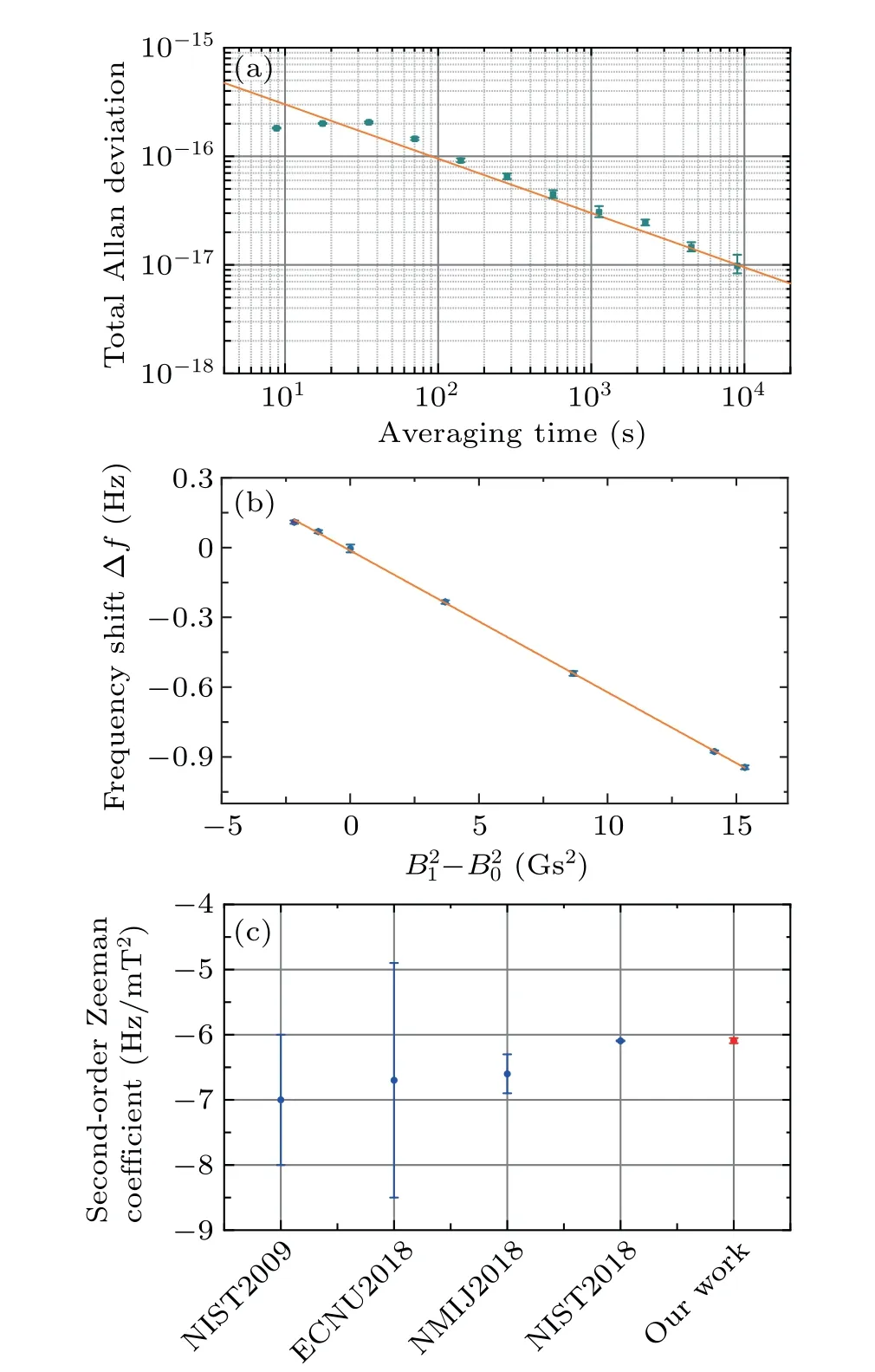
Fig.4.Evaluation of the second-order Zeeman coefficient of 171Yb clock transition.(a)The instability evaluation of interleaved measurements for the second-order Zeeman shift measurement.The solid line represents the white frequency noise asymptote of 9.5×10⁻¹⁶/√τ, where τ is averaging time in seconds.Error bars are 1σ uncertainty.(b)The relationship between the frequency differences Δf and (B21-B20).The second-order Zeeman coefficient is found to be β =-6.09(3) Hz/mT2 by linear fitting (orange line).Error bars represent 1σ standard deviation obtained from the last point of the total Allan deviation of self-comparison.(c)A history of evaluations of the second-order Zeeman coefficient completed by the NIST,[2,25]ECNU,[26]NMIJ.[27]
5.Vector Stark shift
ThemF-dependent Stark shift induced by lattice laser can also lead to energy shift of the magnetic sublevels, including vector and tensor Stark shift.For171Yb,the tensor Stark shift is zero due to the angular momentum ofF=1/2.[28]The vector Stark shift can be written as
whereαVis the vector polarizability,ξis the degree of ellipticity of the lattice laser andE2represents its intensity.For pure circular (linear) polarization,ξ=±1 (ξ=0).Because the vector Stark shift behaves like a pseudomagnetic field along the light propagation axis, it can also cause splitting ofπtransitions like the magnetic field.The vector Stark shift can be canceled by averaged interrogation for equal but oppositemFmagnetic sublevels, but it will degrade the measurement accuracy ofBbiasand the evaluation of the secondorder Zeeman shift.We have already applied a high-quality Glan-Taylor polarizer(extinction ratio>105)for lattice laser before entering the science chamber,which would in principle eliminate the vector Stark shift.However, the birefringence of the vacuum windows can deteriorate the polarization purity of lattice laser, and induces a nonzero vector Stark shift.According to Eq.(5),the vector Stark shift and lattice trap depth are linearly related.Therefore,we can measure the frequency difference of the splitting ofπtransitions at high and low trap depth by self-comparison to extract the vector Stark shift.
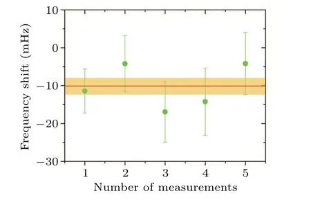
Fig.5.Five measurements of the vector Stark shift for 0.26U0 variation.Green filled circles are each measured value and error bars are standard errors.The red line represents the weighted mean and the orange shaded region represents the statistical 1σ standard deviation of the five measurements.For 0.26U0 trap depth variation,δ fvector=-10.1(2)mHz.
In normal clock operation, the lattice trap depthU0=200Eris extracted from sideband spectrum, whereEris lattice photon recoil energy.We modulate trap depth between 0.74U0andU0in two interleaved servo loops and measure the frequency difference at two trap depths.We repeat this measurement for five times and each measurement time is about four hours.Figure 5 shows that the difference of vector Stark shift at two different trap depth is-10.1(2) mHz.Then we deduce the vector Stark shift of-39(9)mHz for normal clock operation with trap depth ofU0.We have removed the vector Stark shift in the first- and second-order Zeeman coefficient measurements in the above.
6.Conclusion
In this paper, we presented a precise measurement of magnetic constants of171Yb clock transition based on our new optical clock.For normal clock operation, we compensate the background magnetic field to< 1 mGs.The firstorder Zeeman coefficient ofπtransitions is determined to beα=199.49(5) Hz/Gs by measuring the splitting ratio ofπandσtransitions.By self-comparison,the second-order Zeeman coefficient is measured to beβ=-6.09(3)Hz/mT2and the vector Stark shift is-39(9)mHz for our171Yb optical lattice clock.We extrapolate the second-order Zeeman shift to be Δν/ν=(-340±1.8)×10-18at 1.7-Gs bias magnetic fields for our171Yb optical lattice clock.For a normal bias magnetic field of 1 Gs, the second-order Zeeman shift uncertainty can be reduced to 10-19level.
Acknowledgments
Project supported by the National Key Research and Development Program of China(Grant No.2017YFA0304402),the National Natural Science Foundation of China (Grant Nos.U20A2075 and 11803072),and the Strategic Priority Research Program of the Chinese Academy of Sciences (Grant No.XDB21030100).
猜你喜欢
杂志排行

Chinese Physics B的其它文章
- Matrix integrable fifth-order mKdV equations and their soliton solutions
- Comparison of differential evolution,particle swarm optimization,quantum-behaved particle swarm optimization,and quantum evolutionary algorithm for preparation of quantum states
- Explicit K-symplectic methods for nonseparable non-canonical Hamiltonian systems
- Molecular dynamics study of interactions between edge dislocation and irradiation-induced defects in Fe-10Ni-20Cr alloy
- Engineering topological state transfer in four-period Su-Schrieffer-Heeger chain
- Spontaneous emission of a moving atom in a waveguide of rectangular cross section