Development and Control Strategy of Subsea All-Electric Actuators
2022-10-24LIUPengSHENDagangBAYaojiCAOJinfengLIUJieandWANGLihui2
LIU PengSHEN DagangBA YaojiCAO JinfengLIU Jieand WANG Lihui2
Development and Control Strategy of Subsea All-Electric Actuators
LIU Peng1),*, SHEN Dagang1), BA Yaoji1), CAO Jinfeng1), LIU Jie1), and WANG Lihui2)
1)School of Mechanical and Automotive Engineering, Qingdao University of Technology, Qingdao 266520, China 2)Shandong Meichen Industry Group Co., Ltd., Weifang 262200, China
The development of subsea all-electric Christmas trees is an area of focus in the offshore oil industry worldwide. The main difficulties are associated with the development and control strategies for subsea all-electric actuators, which are the most critical components of subsea Christmas trees. A single-motor-level fuzzy PID control with an integrated working condition detection module and a three-motor redundant-level deviation strategy with coupled joint synchronous control were proposed in this paper to realize the real time determination of algorithm parameters according to the working conditions, solve the rapid redistribution problems, and maintain the fast speed of the servo motor of the subsea all-electric tree valve actuator. A synchronous control electrical system was built, tested, and verified through simulation analysis. Test results show that the two redundant servo motors can still control the all-electric valve actuator and provide good synchronization control capabilities despite the failure of one servo motor, and the vertical and horizontal vibration values of the system are within reasonable ranges. The synchronous control strategy can be applied to the synchronous control problem of subsea all-electric production systems, which is of considerable importance for the development of subsea all-electric production systems.
subsea all-electric actuator; redundant-level deviation strategy; synchronous control model; synchronous control strategy; load shocks; strong robustness
1 Introduction
The main battlefield of oil and gas exploration and development has recently focused on ultradeep water. How- ever, ultradeep water problems, such as the ultrahigh hydrostatic pressure, hydraulic flow, and economic cost, seriously restrict the application of conventional all-electric and electrohydraulic systems according to the subsea Christmas tree (Gan, 2018; Liu, 2020a). Following the development trend of deepwater all-electric production systems, global oil technology giants FMC, Cameron, GE, and Aker are racing to increase their R&D investment in key technologies of subsea all-electric trees. The key technology to break through an all-electric tree is to advance the common key technology of an all-electric valve actuator. Subsea all-electric valve actuators are complex electromechanical and hydraulic systems(Cheliyan and Bhattacharyya, 2018). These systems have been operating on the seabed for a long time, and their faults can be attributed to numerous reasons. These systems must be salvaged to land for maintenance once they fail, which costs considerable manpower and material resources. Therefore, improving the reliability and precision of the valve actuator control is of considerable importance (Liu, 2019; Zhao, 2020).
The subsea volume of all-electric actuators is limited due to the harsh subsea environment; thus, using a single motor as a power source is impossible. However, the use of multiple motors will produce new problems (Liu, 2020b, 2020c). Multiple motors acting on the same load will be out of synchronization due to the interference of actual factors. The difficulty in redundant-level control of multiple motors (such as three servo motors) of the all-electric actuator lies in the realization of the conventional speed synchronization of the three servo motors. The technical requirements of fault-tolerant control of the all-electric valve actuator indicate that the two redundant servo motors must quickly complete the power redistribution and speed maintenance when a certain motor fails; that is, the torque can be quickly increased while the speed is unchanged. Each motor outputs 1 unit of torque during normal operation of the three motors, which provides three units of torque to complete the drive. The torque of the two redundant servo motors should be quickly increased to 3/2 units of torque when one motor fails to satisfy the control requirements of all-electric actuators. Parallel and mas- ter-slave synchronous control strategies cannot satisfy the abovementioned complex control requirements, and cross-and deviation-coupled control strategies have been increasingly studied (Wang, 2020).
Limited research literature is available for the synchronous motor control of subsea all-electric valve actuators, but the relevant technology is strictly blocked by the Cameron Company. Fortunately, some common technical research results on the synchronous control of servomotors can be used for reference. For example, Premkumarand Manikandan (2014) proposed a new brushless DC motor controller, which was based on the adaptive neuro-fuzzy reasoning system, to control the brushless DC motor effectively and obtain its performance in the actual working environment through simulations and experiments. Cheng(2014) used the fuzzy PID algorithm to establish the cross-coupling mode to design the multimotor synchronous controller. The master-slave and conventional PID cross-coupling modes are used on the basis of the established multimotor control model. The largest disadvantage of the cross-coupling control strategy is that only two motors can be controlled, while the deviation coupling strategy improves the motor speed compensation link and can be applied to the collaborative control of multiple motors. Li and Sun (2016) proposed a bias coupling control strategy based on the same given control and error compensation idea, which can effectively reduce the complexity of the control structure. Li(2016) developed a new mean deviation-coupled synchronous control strategy, which can guarantee the synchronous performance of multimotor control systems and reduce the complexity of control structures as the number of motors increases. The wide velocity range adaptive synovial observer proposed by Gan(2018) is a sensorless control method for brushless DC mo- tors.
Many studies on different control objects have also been conducted. Rodriguez and Ali (2007) proposed a novel robust digital velocity control scheme to ensure the stability of the closed-loop system and meet the required phase and gain margin. Zhao(2010) introduced a full-order sliding-mode control method to facilitate the convergence of the speed synchronization error between motors to zero. Niu(2015) analyzed and compared the control performance of the centralized control strategies of direct torque control, such as model prediction and duty cycle modulation, and revealed the advantages and disadvantages of each control strategy. Chen and Gong (2017) proposed an adaptive dynamic synovial observation system and used a compensator to eliminate the approximationerror of the test system. Various controller algorithms have also been investigated. Benchabane(2012) introduced a fuzzy synoptic control system for sensorless drivers. Li and Zhu (2019) proposed a robust internal mode control method based on sliding mode control, which had certain transient tracking performance and ensured the tracking accuracy of the servo system. Huo(2018) analyzed the torque output synchronicity of each motor and the three-way vibration of gear under torque master-slave and speed following controls. Shang(2020) proposed a novel dual-space adaptive synchronization control scheme of redundantly actuated cable-driven parallel robots to compensate for the deficiencies of the parameter uncertainty of the mobile platform in the task space. Liu(2021) studied the coordination dynamics of general redundantly full-actuated parallel manipulators and derived coordination dynamics models for driving force coordination and internal force regulation. Associated with coordination dynamics models, two neural network synchronous control methods are proposed for each situation correspondingly.
This paper develops a redundant control system of an all-electric actuator and proposes a two-layer synchronous control strategy of an integrated condition detection module. The remainder of this paper is organized as follows. Section 2 proposes the subsea all-electric Christmas tree fault-tolerant control system. Section 3 shows the synchronous control analysis of all-electric actuators and the mathematical modeling of servo motors. Section 4 investigates the synchronous control strategy of redundant servo motors for subsea all-electric actuators. Section 5 verifies the synchronization control strategy. Section 6 summarizes the paper.
2 Subsea All-Electric Christmas Tree Fault-Tolerant Control System
The all-electric Christmas tree is a fully electronic control system. The fault-tolerant control technology is adopted to satisfy the high-reliability requirements of the electronic control system. The failure of certain components does not affect the normal operation of the mechanical and control systems based on this technology. The principle of the fault-tolerant control system of the all-electric Christmas tree is shown in Fig.1, which is divided into two parts: shore-based and subsea control systems. The main components include the following: master control station, control and communication unit, ground power distribution unit, uninterrupted power supply, subsea power modulation and communication unit, subsea control module, drive unit, valves, and sensors (Liu, 2020d).
Shore-based control system: The main control station is the core and brain of the control system. All control commands are issued by the main control station, and sensor data are recovered to monitor the operating conditions of the Christmas tree in real time. The control and communication unit comprises three PLC processors of identical models. The main control station sends the control instructions to the control and communication unit to complete the command. Simultaneously, the control and communication unit sends the collected data to the main control station. The ground power distribution unit has two main functions. First, this unit provides power support for the mechanical and control systems and converts shore-based AC power to high-voltage direct-current and transmits it to the subsea through the transmission cable. Second, the unit realizes the photoelectric conversion of the control signal, converts the electric signal of the upper computer into an optical signal, and transmits data to the next level. Simultaneously, with the uninterruptible power supply as a redundant power support measure, the uninterrupted power supply is connected to the power supply system when the main power supply system fails.

Fig.1 Principle of the fault-tolerant control system.
Subsea control system: The subsea power modulation and communication unit modulates the power and communication signals transmitted from the shore and sends these signals to the subsea control module. This control module is installed on the all-electric Christmas tree to control the valve driving unit directly. Each valve driving unit drives the opening and closing of the valve through a servo motor.
The final purpose of the control system is to control the servo motor to open and close the valve. The valve actuator controls the pressure compensation section through the control section. All-electric Christmas trees have 12 sets of valves and actuators. The control section of each valve actuator is designed with three servo motors of identi-cal types to provide the opening and closing power of the valve to realize the redundant control. Three motors are simultaneously driven under normal operating conditions. The two redundant motors drive together when a certain motor fails.
Therefore, the synchronization of the servomotor of the control terminal is one of the key issues to consider. If synchronization is absent, then the valve drive will be stuck, and the opening and closing speed of the valve will oscillate. However, the commonly used noncoupled control stra- tegies of parallel and master-slave synchronizations have become increasingly incapable of satisfying the increasingly complex control requirements. This paper proposes a fuzzy PID deviation coupling double-layer synchronization control strategy for all-electric valve actuators. The fuzzy PID control realizes the single-motor level rapid response and precision control, and the deviation coupling control realizes the three-motor redundant-level synchronous error control.
3 Synchronous Control Analysis of All- Electric Actuators and Mathematical Modeling of Servo Motors
The research object of this paper is a brushless DC servo motor, which has the advantages of electronic commutation, absence of wear and sparks, and good airtightness. It has increasingly many applications and has been widely used in robots and electric vehicles. A brushless DC servo motor adopts a double closed-loop control structure, in which the outer loop is a speed loop, forming feedback mechanisms to ensure that the speed follows the change inthe given value and remains stable. PI regulation is adopted to ensure speed regulation accuracy. The three-phase electrical signal is transformed into a static two-phase current and a rotating two-phase current through Clark and Park commutation transformation, respectively, to facilitate the PI regulation. The excitation and torque currents are obtained. The signal commutation is completed after the pulse width modulation. The feedback mechanism of the velocity loop decreases the fluctuation and stabilizes the velocity when the velocity fluctuates. The inner loop is a current loop, thus allowing the current to follow the current setpoint change to improve the dynamic performance of the system. The current loop adopts the hysteresis loop ad- justment, which has a simple structure and rapidly changes the current. The current loop uses the modulation signal output by the position sensor to ensure correct commutation. The control principle is shown in Fig.2.

Fig.2 Control principle.
The mathematical model (Kuzovkin, 2014) of the brushless DC servo motor is expressed as:

whereV,V, andVare phase voltages;R,R, andRare stator winding resistance; i,i, andiare phase currents;L,L, andLare self-inductance;M,M,M,M,M, and Mare mutual inductance;e,e, andeare counter electromotive forces.
The torque of the brushless DC servo motor is expressed as:


whereis the moment of inertia,is the friction,is the angular velocity,Tis the power torque, andTis the motor torque.
The relationship between motor speed and rotation angle is:
A Laplace transform on Eq. (4) is performed to obtain:

The simulation equation after Clark change is expressed as:


whereu,u, anduare phase voltages;vandvare static axis voltages.
The simulation equation after Park change is expressed as:
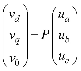

wherev,v, and0are rotating axis voltages.
The simulation parameters are obtained after Clark and Park transformations:


whereψandψare rotating axis stator fluxes;ψis the rotating axis rotor flux;Lis the self-inductance coefficient of the-axis.iis the current of the-axis.
4 Synchronous Control Strategy of Redundant Servo Motors for Subsea All-Electric Actuators
4.1 Fuzzy PID Control Strategy of Brushless DC Servo Motors
The control goal of a single motor is to achieve its rapid response and precision control. Fuzzy PID control is a control algorithm based on fuzzy rules. The basic structure of this algorithm is similar to PID control, except for its independent fuzzy controller. Fuzzy control, which combinesfuzzy theory, fuzzy technology, and automatic control technology, is a widely used control theory. The fuzzy controller aims to fuzzify the signal and perform fuzzy reasoning anddefuzzification.Meanwhile,fuzzificationaimstoadjust the parameters of the PID control.
Specific implementation steps of the fuzzy controller include fuzzification, determination of fuzzy rules, and resolution of fuzziness. First, the deviation signal and the rate of change of the deviation signal are fuzzified.K,K, andK(three parameters of PID) are then solved. Finally, the formula is inserted to realize the PID control. The principle is shown in Fig.3.

Fig.3 Schematic of fuzzy PID controller.
This paper improves the Mamdani algorithm based on the Zadeh algorithm and considers the multidimensional Mamdani algorithm for the fuzzy algorithm. The basic fuzzy reasoning formula is as follows:


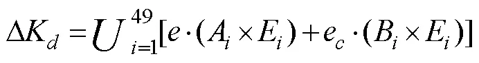
whereis the deviation signal,eis the variation rate of the deviation signal, andA,B,C,D, andEare the fuzzy rule subset.
The FIS editor of MATLAB was used to write the mem- bership function of the fuzzy controller. The fuzzy control rules were written in accordance with the PID tuning principle. The parameterrules are shown in Table 1,andare similar, and the fuzzy controller and PID control are established. The simulator model is shown in Figs.4 and 5. Fuzzy PID uses fuzzy logic and optimizes the parameters of PID in real time according to certain fuzzy rules to overcome the shortcomings of traditional PID parameters that cannot be adjusted in real time. The parametersK,K, andKrules are respectively shown in Tables 1, 2, and 3, and the simulation models of the fuzzy controller and PID control are established. The simulator model is shown in Figs.4 and 5.

Fig.4 Simulation model of fuzzy controller.

Fig.5 Simulation model of fuzzy PID controller.
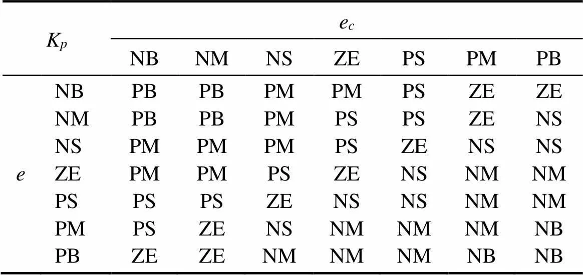
Table 1 Parameter Kp rules

Table 2 Parameter Ki rules
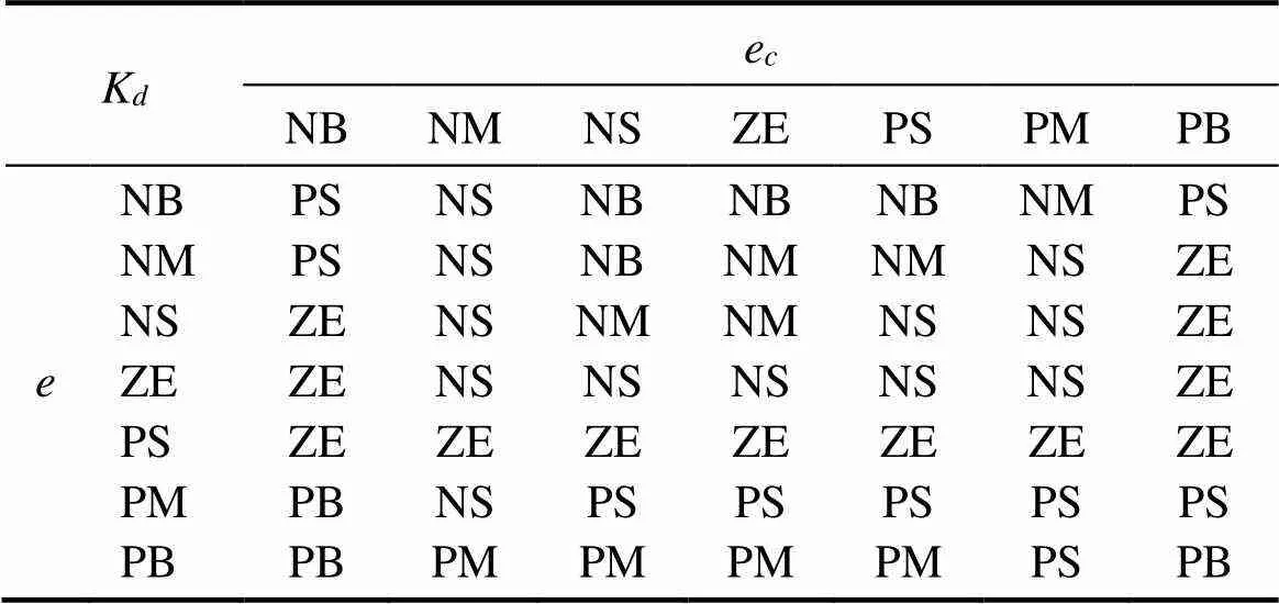
Table 3 Parameter Kd rules
A simulation model of a single brushless DC servo motor is developed in accordance with the mathematical model and principle of the single motor established in Section 2, as shown in Fig.6.

Fig.6 Simulation model of a single brushless DC servo motor.
4.2 Fuzzy PID Deviation Coupling Two-Layer Control Strategy
A slight deviation is unavoidable despite the realized precision control of a single motor through fuzzy PID. Thedeviation will accumulate considering the three-motor redundant control level; thus, the three motors are not synchronized. Therefore, detecting the small deviation signal in advance to compensate and control the accumulated de- viation within a reasonable range is necessary. The synchronization error of two redundant servo motors will increase with the failure of one servo motor. Therefore, the synchronization control effect must be quickly improved.
The motor working condition detection module in the double-layer synchronization control level of deviation coupling is added on the basis of the deviation coupling cooperative control algorithm, and the speed compensation signal is obtained by calculating the motor speed deviation. A detected servo motor fault is fed back to the single-motor fuzzy PID layer, the real time and limited increase in parameter value quickly achieves the speed convergence, and the speed synchronization error is controlledwithin a reasonable range. This principle is shown in Fig.7.

Fig.7 Double-layer synchronization control level of deviation coupling.
The principle of the speed compensator is presented in Fig.8. The speedωof the working motor is obtained, and−1 speed compensation quantitiesK1−K(n−1)are obtained after the comparison and calculation. The compensation is then fed back to the corresponding single-motor level fuzzy PID controller. The working condition detection module obtains two compensation values during the normal operation of the three motors. If one motor fails, then only one compensation valueK1is obtained, and the speed deviation is relatively large. Parameter factorof the fuzzy PID is calculated in real time based on the compensation amount.should be larger than 1 and proportional to the compensation value to ensure the limited finetuning ofK. This paper adopts the logarithmic function based on the natural numberfor processing after comparing the primary, exponential, and logarithmic functions and determines the new Kusing Eq. (16), whereωis the set speed.

Figs.4–8 are related to the principle of three-motor redundant deviation coupling synchronous control, and its simulation model is established in Fig.9. The FCN function module in the figure represents the motor working condition detection module.
4.3 Establishment of Electrical Systems
This study is the first to disclose the self-developed control system applied to subsea all-electric Christmas trees. The fully electric executive control section, which mainly includes three redundant servo motors, the reducer, electromagnetic brake, electromagnetic clutch, ROV interface, and spindle, is shown in Fig.10. The function of the electromagnetic brake is as follows. The main shaft can be stopped by the electromagnetic brake when the valve is kept open for a long time. The power supply of the servo motor can be disconnected during this time to save energy. The outer rotor of the electromagnetic clutch is a gear, which realizes gear transmission with the servo motor mainshaft. The inner rotor is connected to the spindle by a spline.The electromagnetic clutch controls the servo motor to con- nect with the spindle. The servomotor can drive the spindle rotation only when the clutch is powered on. Otherwise,the spindle will be floating and will not self-lock when the failure protection mechanism is started. The ROV interface is reserved in accordance with relevant international standards, and the valve can be closed through the ROV in case of emergencies.
5 Verification of Synchronization Control Strategy
5.1 Theoretical Verification of Control Strategy
The response speed and robustness of the control strategy are the most notable, and the single-motor level control strategy is theoretically verified, as shown in Fig.11. The fuzzy and traditional PID are compared and verified on the same motor, as shown in Fig.11(a). The results show that the designed fuzzy PID in this paper is far superior to the traditional PID in eliminating tracking errors. One step in the figure shows 0.1ms; thus, the fuzzy PID controller designed in this paper stabilizes approximately 0.2s after starting, while the traditional PID control requires 2.3s to stabilize. Fig.11(b) shows that the motor speed substantially fluctuates after the impact load of the Dirac unit impact function is applied to a single motor when the PID control algorithm is used to adjust the system. This fluctuation will seriously decrease the instantaneous speed, and the speed difference of different motors will increase. A risk of stalling is also observed, and the speed callback is slow. Finally, stability can be achieved. However, an overshoot phenomenon, which cannot satisfy the synchronous control requirements of the all-electric Christmas tree valve actuator, is still observed.

Fig.9 Simulation model of the three-motor redundant layer deviation coupling synchronous control.

Fig.10 Fully electric executive control section.
Finally, the completed electrical system is shown in Fig. 12, wherein each of the three servo motors constitutes an all-electric actuator redundant control system.
The fault-tolerant control technical requirements of all-electric valve actuators indicate that the two redundant servo motors must quickly complete power redistribution and speed maintenance during motor failure; that is, the torque can be increased quickly while the speed is maintained to prevent major accidents caused by the failure mechanism. The torque of the two redundant servo motors should be increased quickly when one motor fails to meet the control requirements of the all-electric actuator. The control action curve for fuzzy PID is shown in Fig.13 to understand the effect at the level of three-motor redundant synchronous control. The figure reveals that the speed cur-ves overlap when the three motors are working simultaneously. The speed of the three motors is stabilized after 0.5s, and the control curve is similar to that of the control single-motor curve. This speed stabilization time can still effectively address the control requirements despite its slight delay.

Fig.11 Theoretical verification of the single-motor level control strategy: (a) simulation results of single-motor tracking error, (b) response curves of PID.
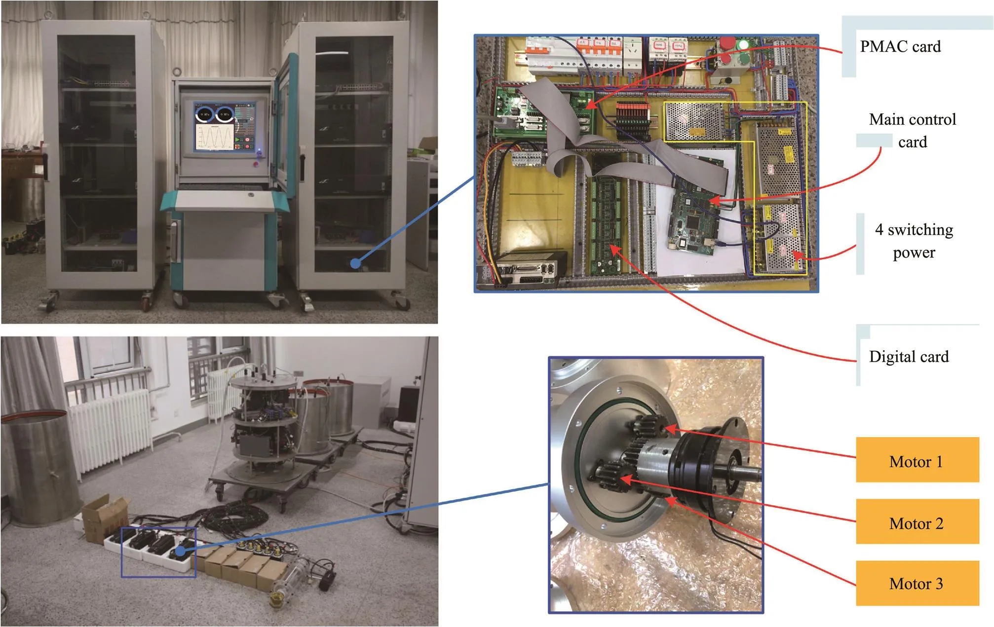
Fig.12 Completed electrical system.
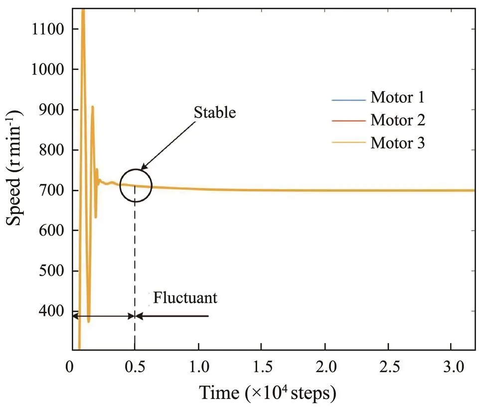
Fig.13 Fuzzy PID control action curve.
The rationality of the proposed redundant control strategy in this paper is verified by simulating two failure conditions of the valve actuator of the all-electric Christmas tree, as shown in Fig.14.
1) Fig.14(a) reveals that the three motors are synchronized at 0.5s, and the operation is stable. The same unit impact function is applied to servo motor 1 for 1.27s to simulate the impact load and the failure of one of the servo motors. The response curves of the three motors are shown in Fig.14(b). The speed of the three servo motors suddenly drops at the moment of load impact. Motor 1 slightly reduces, but the difference in speed of various motors is less than 5rmin−1. The speed of the three servo motors is synchronized and converges to the set speed of 1000rmin−1after 0.14s. Thus, the synchronous control results are good and the control strategy is robust, quickly resisting the effect of the impact load on the system.
2) The frictional resistance caused by the pressure when the valve is closed will finitely increase due to the continuous backlog in the hydraulic balance cylinder based on the proposed all-electric Christmas tree pressure-compensated valve actuator in this paper. Therefore, the load of the servo motor slightly increases. An incremental load is applied to motor 1 and an incremental load with a load function of=(20−4)Nm is applied in the interval of 1.5–3.0s to simulate the actual working conditions. The speed response curves of the three motors are shown in Fig.15. The speeds of the three motors are synchronized, the entire system has no overshoot phenomenon, and the synchronization control result is good after 0.25s.
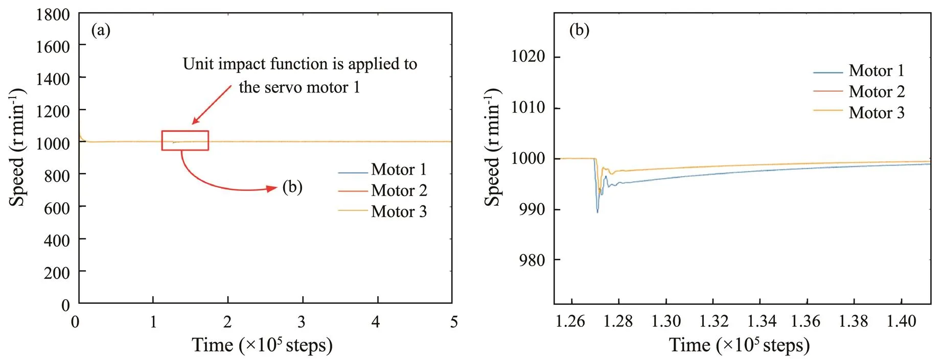
Fig.14 Rational verification of three-motor redundant synchronous control: (a), load impact; (b), load response curves of fuzzy PID deviation coupling synchronous control.

Fig.15 Speed response curves of the three motors.
5.2 Experimental Verification of Control Strategy
1) Control speed test
The device in Fig.16 is built for the verification test based on the synchronous control strategy and developed electrical system. The hydraulic station can provide an initial pressure of 0–2MPa, and its model is HS-10 (rated flow of 12m3h−1and rated power of 0.75kW). The pressure can be adjusted by finetuning the pressure valve of the hydraulic station. PT1 and PT2 pressure sensors (model PCM300; range 0–4MPa; accuracy 0.5% FS) are respectively installed at the inlet and outlet of the valve to monitor the operation status of all-electric actuators. The models of the acquisition card are NI USB-9234 and 231 (the maximum sampling rate is 50kss−1), which are used to collect the signals of the servomotor rotary encoder to the PC and utilize the established electrical control system to control the process.

Fig.16 Speed test system.
The three servo motors drive the spindle together; thus, the motor speed is maintained under the same working condition despite using three or two motors. However, if the motors are out of synchronization, then the motor witha lagging speed trend will produce impeding torque. Therefore, the synchronization control performance of the controller is crucial. A variable load experiment is designed to verify the robustness of the controller under variable working conditions. Multiple operating conditions of the actuator are simulated through the change in inlet pressure. Furthermore, the motor failure is simulated by the power-off method. The speed curve of the servo motor is obtained when the valve is closed by the all-electric valve actuators under inlet pressures of 1.0, 1.5, and 2.0MPa. InTest 1, if the three motors work normally, then the speed curve of the three motors is shown in Fig.17. In Test 2, one of the motors fails (motor No. 3 is cut off in the entire process) when the control system starts, the entire process is driven by two redundant servo motors, and the speed curves of motor Nos. 1 and 2 are obtained, as shown in Fig.18. In Test 3, the control system is started; one of the motors is simulated to have a fault (power off motor No. 3 at 3.5s) after the speed is stabilized, and the motor speed curve is shown in Fig.19. For the convenience of analysis, the data are rounded with an error of ±5; for example, the rotation speed of (995, 1004)rmin−1is rounded to 1000 rmin−1.

Fig.17 Speed curves of three motors.

Fig.18 Speed curves of two redundant motors-1.

Fig.19 Speed curves of two redundant motors-2.
Errors are observed between the convergence curve of the speed and the theoretical results during the test due to the difference between actual and ideal situations, such as the friction between rotating parts and the thermal loss of the motor. Fig.17 shows that the control effect is good whenthe three servo motors simultaneously work. The synchronization effect is good within the allowable range of error, the inlet pressure increases, and the speed is maintained at 1000rmin−1, which satisfies the control requirements of the incremental load. Fig.18 reveals that one servo motor fails during startup, and the two redundant servo motors can complete the control of the fully electric valve actuator. The system also quickly responds and does not oscillate after the speed is stabilized. Fig.19 shows that a motor fails after startup, and the speed slightly fluctuates, but the control system quickly readjusts. The speed stabilizes without overshoot after 0.5s, which satisfies the design requirements. Combined with theoretical verification and experimental results, the ‘fun’ module in the Fig.9 effectively improves the speed convergence, verifies the accuracy of the fuzzy PID deviation coupled with the synchronization control strategy of the integrated working condition detection module, and validates the practicability of the electrical system.
The inlet pressure is adjusted by the hydraulic station to facilitate an increase from 1.0 to 2.0MPa continuously in the first 6s to realize the stepless change in the load, and the speed change curve of the motor is shown in Fig.20. The figure reveals that the continuous change in the load pressure will have a certain impact on the motor speed. The speed will overshoot by a small margin only when the valve is about to close, and the pressure peak occurs under the normal operation of three motors and the stable system. The speed will slightly fluctuate as the pressure continues to rise when one of the motors fails and the redundant two motors work, but the fluctuation range is small. The above analysis proves that the controller has a strong capability to adjust load changes, and the system has high robustness.

Fig.20 Motor speed change curve.
2) Control performance test (vibration performance as the index)
The vertical and horizontal vibration accelerations when the valve and actuator are closed are obtained under inlet pressures of 0, 1.0, 1.5, and 2.0MPa and all three redundant servo motors are working normally, as shown in Figs.21–23. The figures reveal a large vibration in the horizontal and vertical directions when the valve is opened and closed. When the valve opens, the absolute value of the peak vertical vibration acceleration under three inlet pressures is 0.12×10⁻³ms−2, 0.10×10⁻³ms−2, and 0.09×10⁻³ms−2, and that of the peak horizontal vibration acceleration is 0.27×10⁻³ms−2, 0.11×10⁻³ms−2, and 0.08×10⁻³ms−2. When the valve closes, the absolute value of the peak vertical vibration acceleration under three inlet pressures is 0.52×10⁻³ms−2, 0.34×10⁻³ms−2, and 0.29×10⁻³ms−2, and that of the peak horizontal vibration acceleration is 0.17×10⁻³ms−2, 0.52×10⁻³ms−2, and 0.38×10⁻³ms−2. The absolute value of the peak vertical vibration acceleration decreases with the increase in inlet pressure, while the change in horizontal vibration acceleration and inlet pressure demonstrates a stable trend. All vibration values are within a reasonable range (design standard requirements: the vibration acceleration is less than 1×10⁻³ms−2). Thus, the proposed control algorithm in this paper can effectively resist the change in resistance, complete the drive, and demonstrate strong robustness. The control process is relatively stable and does not cause violent vibrations, which fully satisfies the design requirements. Liu(2019, 2020d) also conducted relevant studies.
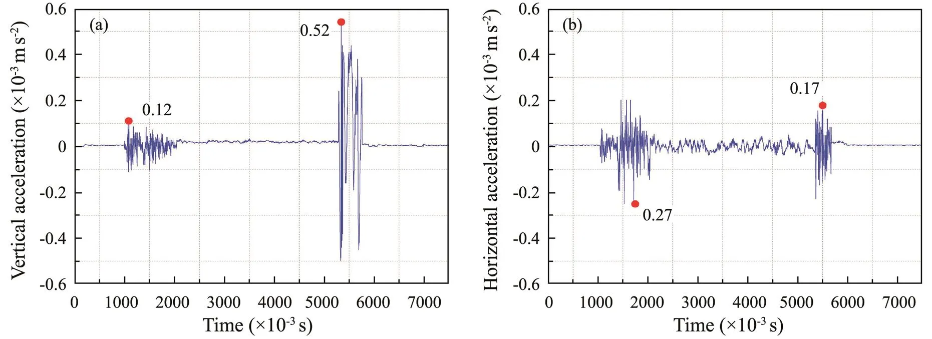
Fig.21 Vibration acceleration of actuator under normal working conditions (1.0MPa).

Fig.22 Vibration acceleration of actuator under normal working conditions (1.5MPa).
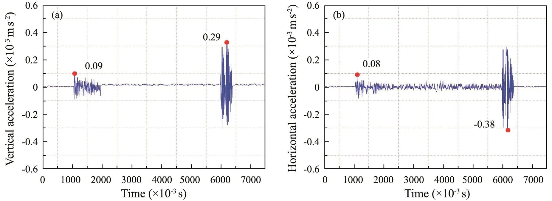
Fig.23 Vibration acceleration of actuator under normal working conditions (2.0MPa).
Servo motor No. 1 is turned off and placed in a floating state to simulate its failure and drive it using the two remaining service motors. The inlet pressures are 0, 1.0, 1.5, and 2.0MPa, and the vertical and horizontal vibration accelerations when the valve and actuator are closed are obtained, as shown in Figs.24–26.
When the valve closes, the absolute value of the peak vertical vibration acceleration under three inlet pressures is 0.15×10⁻³ms−2, 0.17×10⁻³ms−2, and 0.13×10⁻³ms−2, and that of the peak horizontal vibration acceleration is 0.68×10⁻³ms−2, 0.42×10⁻³ms−2, and 0.32×10⁻³ms−2. When the valve closes, the absolute value of the peak vertical vibration acceleration under three inlet pressures is 0.28×10⁻³ms−2, 0.13×10⁻³ms−2, and 0.09×10⁻³ms−2, and that of the peak horizontal vibration acceleration is 0.29×10⁻³ms−2, 0.68×10⁻³ms−2, and 0.38×10⁻³ms−2. A large vibration in the system at the starting and closing moments is observed under the normal operation of the three motors. The closing process (excluding the starting and closing moments) will decrease the vibration ampli- tude due to the pressure balancing effect. The vibration during closing will be more intense than that of starting due to the inertia force of the gate. The comparison of Figs.21–23 reveals that the control process is not as stable as the normal operation during servo motor failure. Such instability is reflected in the vertical and horizontal vibrations, especially in the closing process, as shown in the red dotted line box in the figure. The application point of the driving force changed from three to two points due to the failure of one of the motors, resulting in a decrease in the force balance of the intermediate spindle (as shown in Fig.10). A certain hindering torque is observed despite the floating state of the failed motor, which further increases the complexity of the working conditions. Therefore, the above factors increased the degree of vibration. However, regardless of the inlet pressure, the vibration value of the valve actuator is within a reasonable range. This finding verifies that the proposed control strategy in this paper has superior performance in power distribution, and the valve actuator has no uncontrolled vibration.
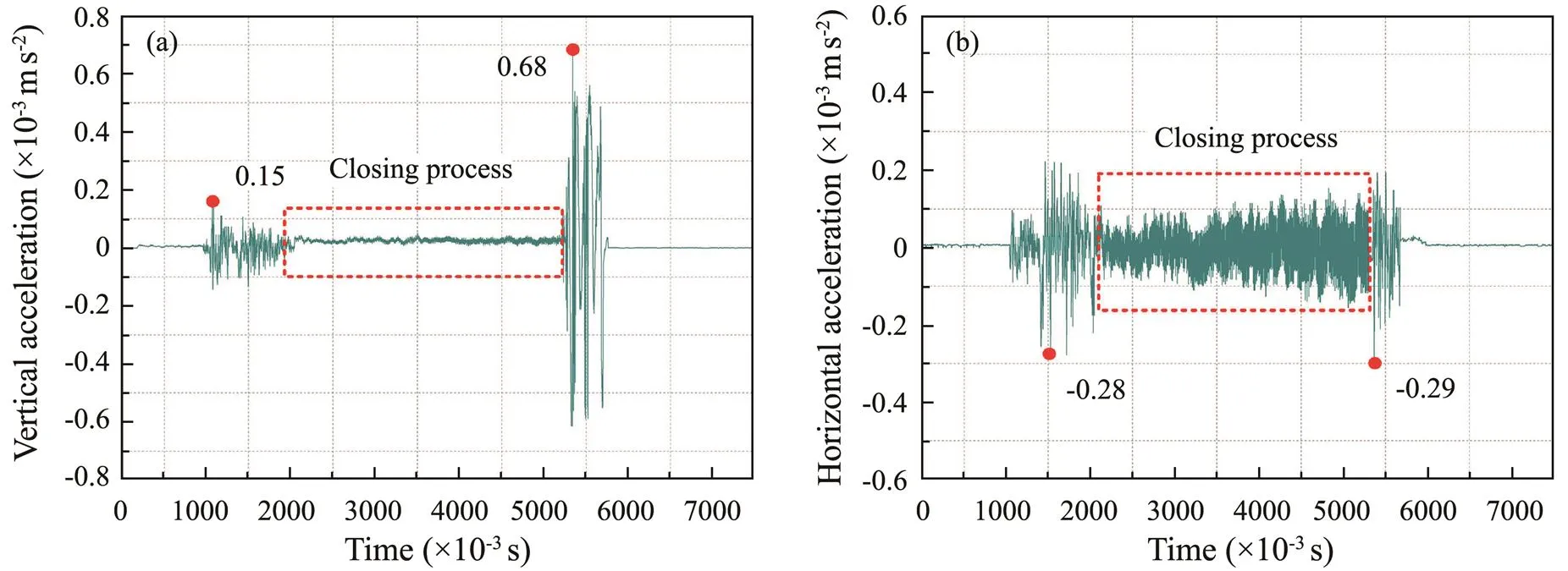
Fig.24 Vibration acceleration of actuator under abnormal conditions (1.0MPa).

Fig.25 Vibration acceleration of actuator under abnormal conditions (1.5MPa).

Fig.26 Vibration acceleration of actuator under abnormal conditions (2.0MPa).
6 Conclusions
The framework of a fault-tolerant control system for an all-electric Christmas tree is proposed, and the synchronization control strategy of redundant servo motors forsingle-channel valve actuators is studied. A combined synchronous control strategy of single-motor level fuzzy PID control and three-motor redundant-level deviation coupling control is proposed, which integrates the working condition detection module. The following conclusions are obtained.
1) The comparison and verification of the fuzzy and traditional PID of the same motor show that fuzzy PID is far superior to traditional PID in eliminating tracking errors. The designed single-motor fuzzy PID controller in this paper stabilizes approximately 0.2s after startup, and the response speed is fast.
2) The three motors are synchronized at 0.5s when the actuator is started and the operation stabilizes. An impact load is suddenly applied to servo motor 1 under the system running for 1.27s. The speed of the three servo motors suddenly drops at the load impact. However, the speeds of the three servo motors synchronize and converge to the set speed of 1000rmin−1after 0.14s, indicating good synchronization control results and robust control strategies.
3) A gradually increasing load with a load function of=(20−4)Nm is applied to motor 1 in the interval of 1.5–3.0s. The speed response curves of the three motors are synchronized after 0.25s, and no overshoot is observed in the entire system, which is consistent with the all-electric actuator control requirements.
4) The control effect of the three servo motors simultaneously working is good, the synchronization effect is satisfactory, the inlet pressure increases, and the speed is maintained at 1000rmin−1under inlet pressures of 1.0, 1.5, and 2.0MPa, thereby satisfying the control requirements of increasing load. The two redundant servo motors can completely control the all-electric valve actuators when one servo motor fails, which satisfies the design requirements.
5) The vertical and horizontal vibration values of the system during normal operation and failure of a servo motor are within a reasonable range under inlet pressures of 1.0, 1.5, and 2.0MPa. This finding verifies that the proposed control strategy in this paper has superior performance in power distribution, and the valve actuator has no uncontrolled vibration, which satisfies the design requirements.
Acknowledgements
The authors wish to acknowledge the financial support of the Shandong Provincial Natural Science Foundation (No. ZR2021QE059), the National Natural Science Foundation of China (No. 51974169), and the Key R&D Program of Shandong Province (No. 2019GGX101020).
Benchabane, F., Abdenacer, T., Ouafae, B., Khaled, Y., and Davide, T., 2012. Sensorless fuzzy sliding mode control for permanent magnet synchronous motor fed by AC/DC/AC converter., 3 (3): 221-229.
Cheliyan, A. S., and Bhattacharyya, S. K., 2018. Fuzzy fault tree analysis of oil and gas leakage in subsea production systems., 3 (1): 38-48.
Chen, S. Y., and Gong, S. S., 2017. Speed tracking control of pneumatic motor servo systems using observation-based adap- tive dynamic sliding-mode control., 94: 111-28.
Cheng, S. Y., Ji, W. G., and Wang, Z. J., 2014. The cross-coupled synchronous control of multi servo motors based on fuzzy-PID.,22 (4): 54-57.
Gan, M. G., Zhang, M., Zheng, C. Y., and Chen, J., 2018. An adaptive sliding mode observer over wide speed range for sensorless control of a brushless DC motor., 77: 52-62.
Huo, J. Z., Wu, H. Y., Zhu, D., Sun, W., and Bao, Y. N., 2018. TBM electromechanical coupling modeling and comparative analysis of synchronous drive control strategy., 1: 17.
Kuzovkin, V. A., Filatov, V. V., and Chumaeva, M. V., 2014. Nonlinear models of dynamic processes in impulse control sys- tems of brushless DC motors., 53 (3): 420-429.
Li, L. B., and Sun, L. L., 2016. Multi-channel synchronization control based on mean of deviation coupling control., 127 (8): 3703-3707.
Li, L. B., Sun, L. L., and Zhang, S. Z., 2016. Mean deviation coupling synchronous control for multiple motorssecond-order adaptive sliding mode control., 62: 222-235.
Li, P., and Zhu, G. L., 2019. Robust internal model control of servo motor based on sliding mode control approach., 93: 199-208.
Liu, G. J., Li, H. Y., Qiu, Z. Z., and Li, Z. X., 2020a. A com- prehensive numerical analysis of cross-flow vortex-induced vib- rations for top tension risers under different flows., 32 (2): 27102.
Liu, G. J., Li, H. Y., Qiu, Z. Z., Leng, D. X., Li, Z. X., and Li, W. H., 2020b. A mini review of recent progress on vortex-induced vibrations of marine risers., 195: 106704.
Liu, G. J., Sun, Y. F., Zhong, B. L., Xie, Y. C., Incecik, A., and Li, Z. X., 2020c. Analysis of wind load effect on key com- ponents in a jack-up offshore platform., 101: 102263.
Liu, P., Liu, Y. H., Cai, B. P., Wu, X. L., Wang, K., Wei, X. X.,, 2020d. A dynamic bayesian network based methodology for fault diagnosis of subsea Christmas tree., 94: 101990.
Liu, P., Liu, Y. H., Wei, X. X., Xin, C., Sun, Q., and Wu, X. L., 2019. Performance analysis and optimal design based on dyn- amic characteristics for pressure compensated subsea all-elec- tric valve actuator., 191: 106568.
Liu, X. F., Yao, J. T., Li, Q., and Zhao, Y. S., 2021. Coordinationdynamics and model-based neural network synchronous con- trols for redundantly full-actuated parallel manipulator., 160: 104284.
Niu, F., Wang, B. S., Babel, A. S., Li, K., and Strangas, E. G., 2015. Comparative evaluation of direct torque control strategies for permanent magnet synchronous machines., 31 (2): 1408-1424.
Premkumar, K., and Manikandan, B. V., 2014. Adaptive neuro-fuzzy inference system based speed controller for brushless DC motor., 138: 260-270.
Rodriguez, F., and Emadi, A., 2007. A novel digital control tech- nique for brushless DC motor drives., 54 (5): 2365-2373.
Shang, W. W., Zhang, B., Cong, S., and Lou, Y. J., 2020. Dual-space adaptive synchronization control of redundantly-actuated cable-driven parallel robots., 152: 103954.
Wang, H., Li, X., Liu, X., Karkoub, M., and Zhou, L., 2020. Fuzzy sliding mode active disturbance rejection control of an autonomous underwater vehicle-manipulator system., 19 (5): 1081-1093.
Zhao, D. Z., Li, C. W., and Ren, J., 2010. Speed synchronisation of multiple induction motors with adjacent cross-coupling control., 4 (1): 119-128.
Zhao, Y., Dong, S., Jiang, F., and Soares, C. G., 2020. System reliability analysis of an offshore jacket platform., 19 (1): 47-59.
January 25, 2021;
July 16, 2021;
February 20, 2022
© Ocean University of China, Science Press and Springer-Verlag GmbH Germany 2022
. E-mail: peng_liu@qut.edu.cn
(Edited by Xie Jun)
杂志排行

Journal of Ocean University of China的其它文章
- Variations in Dissolved Oxygen Induced by a Tropical Storm Within an Anticyclone in the Northern South China Sea
- Intensity of Level Ice Simulated with the CICE Model for Oil-Gas Exploitation in the Southern Kara Sea, Arctic
- Learning the Spatiotemporal Evolution Law of Wave Field Based on Convolutional Neural Network
- Acoustic Prediction and Risk Evaluation of Shallow Gas in Deep-Water Areas
- In Situ Observation of Silt Seabed Pore Pressure Response to Waves in the Subaqueous Yellow River Delta
- Composition, Source and Environmental Indication of Clay Minerals in Sediments from Mud Deposits in he Southern Weihai Offshore,Northwestern Shelf of the South Yellow Sea, China