Simulation and Optimization of a Double-Helical Rotor Wave Energy Converter
2022-10-12XinhuiChenHongzhouHeandPengyuanSun
Xinhui Chen,Hongzhou He,2 and Pengyuan Sun,2
Abstract This paper presents a new type of double-helical rotor wave energy converter (WEC), which consists of two isolated sets of helical rotor structures(inner and outer).This device can generate electricity by using the rising and falling energy of a wave. The rotors are simulated and optimized by Fluent. Each rotor’s blades are simulated and analyzed, which are separately changed in terms of helix angle,shape,and thickness.The simulation result shows that,for both inner and outer helical rotors, the energy harvesting efficiency is the highest when the blade helix angle is 45°. Triangular blades have better hydrodynamic performance than square and circular blades.The energy harvesting efficiency of 15 mm thick blades is higher than that of 75 mm thick blades.
Keywords Sustainable energy;Wave energy;Double-helical rotor WEC;Structural optimization;Numerical simulation
1 Introduction
Energy is the most important foundation of human social progress and one of the basic driving forces of social and economic development. Recently, the continual increase in energy consumption globally is estimated as 9 954 Mtoe(million tons of oil equivalent)≈115 765 TWh in 2020(Liu et al. 2021). However, the dependence on fossil energy causes serious environmental pollution, such as carbon emissions.To achieve the carbon peak and carbon neutrality targets, China has implemented plans to decrease carbon dioxide emissions and establish a green, low-carbon, and circular economy(Cheng and Chen 2021).
Wave energy,which is the kinetic and potential energy of sea surface waves, has been widely considered worldwide(Ružinski et al. 2008; Liao and Wang 2010). With its continually available high-density energy (estimated as 146 TWh/year)(Edenhofer et al. 2011), the exploitation of wave energy is promising due to its high resource availability and enormous potential for electricity production (Lenee et al. 2011;Al-Habaibeh et al. 2010). Global wave energy has been increasing at around 0.4% annually since 1948 due to significant increases in ocean wave heights caused by anthropogenic global warming(Reguero et al.2019).
At present, more than 4 000 wave energy conversion technologies exist (Tan et al. 2011), which can be classified by location,working principle,or power take-off(PTO)system. The WECs can be classified in All-electric type,Hydraulic type and Turbine type by PTO system(Xiao et al.2021). However, ocean wave energy technology has not converged into one technical stream because of many factors and challenges, such as low generation efficiency, high cost of power generation,and poor engineering reliability.
To overcome the above-mentioned challenges, WECs with unidirectional rotational turbine-type PTOs have been developed by many researchers. Some of these PTOs are known as self-rectifying turbines, which are employed in oscillating water column (OWC)-type wave energy plants(Kaneko et al. 1991). The self-rectifying turbines use air as an intermediate to drive the generator to convert wave energy into electrical power without contacting the corrosive seawater. Others use seawater as an intermediate, such as the counter-rotating self-adaptable WEC presented by Sun and Cong (Sun et al. 2018; Cong et al. 2018) and the vertical-axis unidirectional rotor WEC presented by Yang et al. (2018). These WECs with unidirectional rotational PTOs need only the vertical displacement of waves to operate, and they can function in sea state conditions of the low and high wave amplitudes.Moreover,because there is no requirement for additional intermediate steps, they can be simple in design, resulting in high robustness and the ability to survive in harsh ocean environments.
To improve the efficiency of the turbine-type PTOs, researchers studied and optimized the geometric parameters of the PTOs to increase the power production efficiency.Shehata et al.(2016)investigated the effect of airfoils with a suction slot on the torque coefficient and a stall condition as well as the entropy generation due to viscous dissipation. Shehata et al. (2017) researched the second law efficiency and entropy generation characteristics around different blades used in a Wells turbine under oscillating flow conditions. Wang et al. (2020) used biomimetics to optimize the Wells turbines’ blades; the hawkmoth wing-type blades have higher efficiency at a high angle of attack.Sun et al. (2018) studied the counter-rotating self-adaptable WEC through modeling and computational fluid dynamics(CFD) analysis and found that the efficiency is greatly influenced by the relative flow velocity,the blade angle,and the interaction between the upper and lower absorbers.Yang et al. (2018) proposed an experimental study of two types of vertical-axis unidirectional rotors with cup-shaped blades to investigate rotor characterization.
This paper presents a double-helical rotor WEC based on our previous studies (Chen 2014; Li 2015; Liu et al.2017). The main components of the double-helical rotor WEC are the fairing, rotor, and sealing plates. Compared with near-commercial designs, such as oscillating water columns,overtopping types,and flapping devices,the WEC has several advantages, including a small footprint, a simple exchange process, and convenient modular integration.Unlike other kinds of point-absorbing WECs,such as PowerBuoy and Jida 1 WEC, the double-helical rotor WEC has an ingenious mechanism that can rotate in the same direction whether the wave is rising or falling.Thus,the doublehelical rotor can generate direct current steadily. Meanwhile,the overall efficiency of the WEC can be higher theoretically because there is no requirement for additional intermediate energy conversion steps.
This study aims to optimize the geometric parameters of the double-helical rotor WEC. Through modeling and CFD analysis, the effect of the geometric parameters on the energy harvesting efficiency is investigated,and the numerical results are discussed.
2 WEC description
The overall structure of the double-helical rotor wave energy convertor is shown in Figure 1.This device mainly consists of three functional modules: the fairing part, the double-helical rotor part, and the sealing plate part. The fairing can protect the rotor and converge seawater flow.The double-helical rotor is the main energy harvesting mechanism of the device, which converts wave energy into rotating mechanical energy. The sealing plates control the flow in and out.

Figure 1 Schematic of the double-helical rotor wave energy generator
The double-helical rotor wave energy converter (WEC)uses two sets of helix blade structures (inner and outer) to allow the rotor to move in the same direction whether the seawater rises or falls. Its working principle is as follows:When seawater rises, the lower sealing plate blocks the outer helical entrance under the action of water flow so that water flow can enter through the inner helical entrance only, as shown in Figure 2. Similarly, when seawater falls,the upper sealing plate blocks the inner helical entrance under the action of water flow and gravity so that water can enter through the outer helical entrance only,thus driving the rotor to rotate clockwise,as shown in Figure 3.
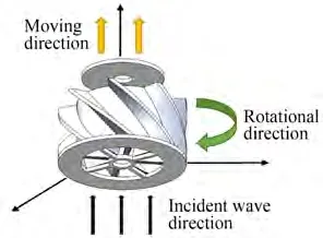
Figure 2 Working principle of rising state

Figure 3 Working principle of sinking state
3 Mathematical models
3.1 Wave energy absorbing efficiency
The energy conversion efficiencyeof the wave energy conversion device is defined as the ratio of the wave energyEpcaptured by the WEC and the incident wave energyEwper unit time.

where the mechanical powerNof the double-helical rotor WEC is

whereρis density,gis gravity;Hsis wave height,andTeis wave period.
3.2 Linear wave theory
The analytical solutions were derived based on the potential flow method. According to Kelvin’s theorem, if a wave is regarded as an ideal incompressible homogeneous fluid under the action of a gravitational field, then its velocity potentialφ(x,y,z,t)satisfies the Laplace equation

wherexandzare the horizontal and vertical positions, respectively;tis time;andCis a constant.
However, the DFSBC and KFSBC have the secondorder term, which makes solving the equations difficult.To ignore the second-order term,the wavelength is assumed to be much bigger than the amplitude to linearize the boundary conditions. Consequently, the DFSBC and KFSBC are simplified as

wherek=2π/λis the wave number,c=λ/Teis the wave speed,His the amplitude,H0is the amplitude of the regular wave,dis the water depth,λis the wavelength, andωis the wave frequency.
3.3 Governing equations for simulation
Li and Yu (2012) extensively studied different methods for modeling point-absorbing WECs, including analytical methods, boundary integral equation methods (BIEM),and Navier-Stokes (N-S) equation methods (NSEM). The analytical solution can be used for simple geometries only,while BIEM and NSEM can be used for more complicated and realistic ones. However, for the double-helical rotor WEC,the nonlinear interaction between waves and the device, such as the viscous force and wave breaking, should be considered.This paper focuses on the motion inside the WEC, but the BIEM uses radiation and diffraction methods to simulate hydrodynamic forces around the WEC.Therefore, the NSEM is used to model the double-helical rotor WEC in this paper, and the Fluent software is used for simulation. As a commercial CFD software, the governing equations of Fluent are the continuity equation and the N-S equation, and the k-epsilon model is one of the most widely used schemes for modeling turbulent flow.
Solving N-S equations directly under the current computational conditions is difficult. To reduce the computational costs and maintain the precision of the N-S equations,the time-averaged concept was first proposed by Osborne Reynolds (Reynolds 1995). Each instantaneous quantity in turbulent motion can be decomposed into time-averaged and fluctuating components. As a result, the governing equations in Cartesian coordinates can be written as follows(Ansys 2011):
Continuity equation:

wherepis the pressure,μis the viscosity, andδijkis the Kronecker delta(i,j=1,2,3).
However, the flow in the double-helical rotor WEC is a viscous and incompressible turbulent flow without the consideration of energy variation.When the rotational rotor is calculated, the reference coordinate system is used more frequently. Therefore, the N-S equations in the reference coordinate system can be described as

wherektrepresents the turbulence kinetic energy, andμtis the turbulent viscosity.
On the basis of the assumption, the Spalart-Allmaras(S-A) model,k-epsilon model, andk-omega model were proposed to compute the turbulent viscosityμt(Cui et al.2019).Thek-epsilon model is used for calculation because of its advantages,such as high calculation speed and applicability to the rotational rotor.
Thek-epsilon model, which is a semi-empirical model,calculates the turbulent viscosity by solving the turbulent kinetic energykequation and the turbulent dissipation rateεequation(Liu,2019).
The turbulent kinetic energy equation and diffusion equation are as follows:


4 Setting of model parameters and boundary conditions
For the double-helical rotor WEC, the blade helix angle and thickness are two important influencing factors that affect the wave energy harvesting based on the cascade flow theory (Liu et al. 2017). In addition, the shape of the blades will affect the energy harvesting efficiency of the rotor(Wang et al.2020).Thus,the blade helix angle,shape,and thickness are simulated.The sea trial prototype model is used for simulation.The initial parameters are shown in Table 1.

Table 1 Initial model parameters
The physical definition of helix angle is

During the simulation, the parameters change separately.The helix angle of the blade is set as 30°, 37.5°, 45°,52.5°, and 60°, as shown in Figure 4. The shapes of the blades are square(the cross section of the blade is square),triangle (the cross section of the blade is triangular), and circle (the edge of the blade is a half-cylinder, and circle blade is the shortened form in this paper), as shown in Figure 5.The blade thicknesses are 15, 45, and 75 mm, as shown in Figure 6.
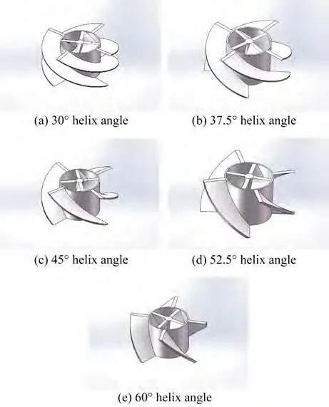
Figure 4 Model drawing of devices with different helix angles

Figure 5 Model drawing of devices with different blade shapes
Devices with different parameters are modeled in 3D,and then unstructured tetrahedral meshes are generated by Mesh and imported into Fluent. To simulate the bidirectional flow of seawater, when the seawater rises, the boundary conditions of the wave inlet are set as the velocity inlet, and the wave inlet velocities are set as 0.5, 1.0, 1.5,2.0,and 2.5 m/s.The boundary of the wave outlet is set as the pressure outlet.When the sea water falls, the positions of the wave inlet and wave outlet are exchanged;the same is applied to the boundary conditions. The wave inlet velocity is set as-0.5,-1.0,-1.5,-2.0,and-2.5 m/s,respectively. The plus-minus sign represents the direction of wave flow.The Semi-Implicit Method for Pressure-Linked Equations (SIMPLE) algorithm (Patankar and Spalding 1983) is selected to solve the pressure-velocity coupling.The SIMPLE algorithm and its variants are widely used for solving N-S equations. The standard wall function is used to address the pressure-velocity coupling relationship near the wall. The medium is water-liquid with a density of 998.2 kg/m3and dynamic viscosity of 0.001 308 Pa·s.

Figure 6 Model drawing of devices with different blade thicknesses
5 Results and discussions
The numerical analysis in terms of the power of the helical rotor under different helix angle, blade shape, and thickness are discussed in this section.The power is calculated according to Equation(3),and the power can be used to evaluate the harvesting efficiency under the same incident wave according to Equation(2).
5.1 Influence of blade helix angle
The relationship between the blade helix angle and the rotor power of the inner and outer helical rotors is shown in Figure 7.
In Figure 7(a), the power of the outer rotor increases first, decreases with the increasing blade helix angle, and reaches the maximum when the helix angle is 45°. This trend becomes apparent with increasing wave velocity.When the incoming flow velocity is 2 m/s, the power of the outer rotor with a 45° helix angle is 76.55% higher than that with a 30° helix angle. In Figure 7(b), when the helix angle is less than 45°,the power of the inner rotor increases with the increasing helix angle, and the increment is small.When the helix angle is greater than 45°,the power of the inner rotor decreases with the increasing helix angle, and the decrement is large. When the incoming flow velocity is 2 m/s,the inner rotor with a 45°helix angle obtains power that is 56.48% higher than that with a 60°helix angle.

Figure 7 Relationship curve of rotor power with blade helix angle
The pressure distribution on the inner and outer helical rotor blades with 30°,45°,and 60°helix angles are shown in Figures 8 and 9.
For the blades of the outer helical rotor, when the helix angle is 30°,the pressure on the blade surface near the water inlet is high (the average of the high-pressure area is about 9.95 × 10²Pa). Meanwhile, the pressure distribution changes abruptly, and the high-pressure area transitions rapidly to the low-pressure area. The low-pressure area is larger than the high-pressure area and is distinct from it,as shown in Figure 8(a),because the blade with a smaller helix angle bears a larger water impact area. The component perpendicular to the blade surface near the water inlet is expected to be larger. In addition, the abrupt change of the pressure makes the shear stress concentrate on the blade,causing the blade to rupture easily.As shown in Figure 8(b),when the helix angle is 45°,the blade pressure distribution is relatively uniform, indicating that the blade can better adapt to the impact water flow. Therefore, under the same conditions, the outer helical rotor with 45° helix angle blades has greater efficiency. As shown in Figure 8(c),when the helix angle is 60°,the blade pressure distribution is uniform. Near the water inlet, the pressure is high, then it decreases and forms a large medium-pressure area (the average is about 1.94×101Pa).However,for the large helix angle, the pressure on the blade surface is generally small because the area in contact with the water flow of the large helix angle blade is small.

Figure 8 Pressure distribution diagram of blades with different helix angles of the outer helical rotor

Figure 9 Pressure distribution diagram of blades with different helix angles of the inner helical rotor
For the inner helical rotor, when the helix angle is 30°,the pressure on the blade surface near the water inlet is high, but the high-pressure area is small and adjoins the low-pressure area. Meanwhile, the low-pressure area is larger than the high-pressure area,as shown in Figure 9(a).When the helix angle is 45°, the pressure on the blade is large and evenly distributed, as shown in Figure 9(b). For the 60° helix angle blade, the pressure distribution becomes uniform, and the pressure on the blade surface near the water inlet is high and then decreases, forming a smooth medium-pressure area, as shown in Figure 9(c).For the inner helical rotor, the pressure distribution on the 45° helix angle blade changes more evenly than that on the 30°helix angle blade,and the pressure on the 45°helix angle blade is larger, thus having greater efficiency under the same conditions.
The velocity vector distribution diagrams of the inner and outer helical rotor blades with 30°, 45°, and 60° helix angles are taken for flow field analysis. The results are shown in Figures 10 and 11.

Figure 10 Distribution of the velocity vector of the outer helical rotor blade with different helix angles

Figure 11 Distribution of the velocity vector of the inner helical rotor blade with different helix angles
In Figure 10(a), the outer helical rotor has two lowspeed areas and high-speed areas on the blade surface with a 30° helix angle.The low-speed and the high-speed areas are not adjacent. One low-speed area is concentrated on the inlet side, and the other is concentrated on the outlet side.One high-speed area is concentrated on the middle of the blade near the rotor hub, and the other is concentrated on the outlet side.Accordingly, the distribution of the velocity vector of the blade is not uniform and may negatively affect the operation. In contrast, the velocity vector distribution of the blade with a 45° helix angle is more uniform, and the radial velocity is larger, indicating that such a blade can better adapt to water impact and cause less flow loss, as shown in Figure 10(b). As shown in Figure 10(c),the velocity vector distribution of the blade with a 60° helix angle is relatively uniform, but the radial velocity is small, indicating that the blade cannot utilize water flow for work efficiently.
Figure 11(a) shows the velocity vector distribution of the blade surface with a 30°helix angle.A high-speed area is present in the middle of the blade surface, surrounded by the medium-speed area, and the medium-speed area is surrounded by the low-speed area. However, the highspeed area is generally small, and the transition between the low-speed zone and the high-speed zone is rapid, indicating that the rotor with a 30° blade helix angle will not perform well.Figure 11(b)shows the velocity vector distribution of the blade surface with a 45° helix angle. The blade velocity vector distribution is uniform, and the transition from low to high speed is slow. The distribution range of high speed is large, indicating that the blade will work well. Figure 11(c) shows that the velocity vector of the blade with a 60° helix angle is evenly distributed, but the velocity vector is small. Accordingly, the blade will not work as well as one with a 45°helix angle.
5.2 Influence of blade shape
The relationship between the blade shape and rotor power of the inner and outer helical rotors is shown in Figure 12.
Figure 12 shows that for the inner and outer helical rotors,the blade shape has little influence on the rotor power when the inflow velocity is small. However, when the inflow velocity increases, the power of the triangular blade is higher than that of the square blade and circular blade.When the inflow velocity is 2 m/s, the power of the outer helical rotor with a triangular blade is 28.68% higher than that of the circular blade. The power of the inner helical rotor with a triangular blade is 15.72% higher than that of the circular blade, indicating that the energy harvesting efficiency of the triangular blade is higher than that of the circular blade and the square blade.
The pressure distribution diagrams of blades with different shapes of inner and outer helical rotors are shown in Figures 13 and 14.
In Figures 13 and 14, for the outer helical rotors, the pressure distribution of the three kinds of blades is very similar.The pressure at the inlet is high and then decreases along the axial direction gradually,forming a triangular area of high pressure and medium pressure. The average pressure on the triangular blade is maximal (about 9.04 ×10²Pa),and the quadrate blade is about 5.69×10²Pa.The pressure on the circular blade is about 3.64×10²Pa,being the lowest of the three kinds of blades. This condition can explain why the rotor with a triangular blade obtains the maximum power and the highest wave energy harvesting efficiency.

Figure 12 Relationship curve of rotor power with blade shape
For the inner helical rotors, the pressure distribution of the three kinds of blades is similar. The low-pressure area is larger than the high-pressure area, and the high-pressure area is concentrated on the water inlet side. This finding shows that the blade shape does not have a considerable influence on the rotor power at a small inflow velocity for the inner helical rotors.
The velocity vector diagrams of blades with different shapes of the inner and outer helical rotors are shown in Figures 15 and 16.
In Figure 15,for the outer helical rotor,the velocity vector distribution of the triangular blade is relatively uniform,as shown in Figure 15(b).Compared with the square blade,the triangle blade has a larger high-speed area.Compared with that of circular blades,the velocity vector of triangular blades changes more stably, and the range of low speed is smaller. Therefore, triangular blades can obtain greater torque.
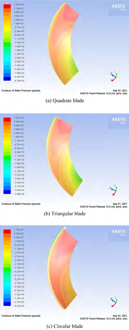
Figure 13 Pressure distribution diagram of blades with different shapes of outer helical rotors
In Figure 16, for the inner helical rotor, the high-speed region of the velocity vector of the triangular blade is distributed more widely. In addition, the transition from the low-speed zone to the high-speed zone is smoother, as shown in Figure 16(b). The velocity vector of the circular blades is small, and the range distribution of the highspeed area is narrow,as shown in Figure 16(c).The velocity vector value of the circular blade is small,and the range distribution of the high-speed area is narrow, as shown in Figure 16(c).The velocity vector distribution of the square blades is between that of the triangular blades and the circular blades,as shown in Figure 16(a).

Figure 14 Pressure distribution diagram of blades with different shapes of inner helical rotors
5.3 Influence of blade thickness

Figure 15 Distribution of the velocity vector of the outer helical rotor blade with different shapes
The relationship between blade thickness and rotor power of the inner and outer helical rotors is shown in Figure 17.

Figure 16 Distribution of the velocity vector of the inner helical rotor blade with different shapes
In Figure 17, for the inner and outer helical rotors, the blade thickness has little influence on the rotor power when the incoming flow velocity is low. However, when the incoming flow velocity increases, the thinner blade rotor has a higher power.When the flow velocity is 2.5 m/s,the power of the outer helical rotor with a 15 mm thick blade is 17.67%higher than that of the rotor with a 75 mm thick blade,and the power of the inner helical rotor with a 15 mm thick blade is 37.81%higher than that of the 75 mm thick blade. This finding means that the blade thickness has a certain influence on the wave energy harvesting efficiency of the double-helical WEC.
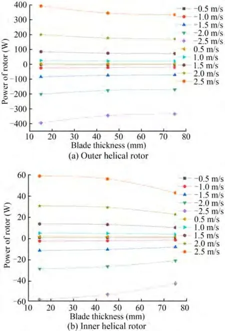
Figure 17 Relationship curve of rotor torque and blade thickness
The pressure distribution diagrams of blades of different thicknesses of the inner and outer helical rotors are shown in Figures 18 and 19.
In Figure 18, for the outer helical rotor, the high-pressure area of the 15 mm thick blade is larger than that of a 75 mm thick blade. The average pressure of the 15 mm thick blade is about 8.21×10²Pa,which is larger than the 2.97 × 10²Pa of the 75 mm thick blade, and the pressure distribution of the 15 mm thick blade is more uniform than that of the 75 mm thick blade. The blade with 15 mm thickness has a wide distribution of high-pressure areas, a small pressure gradient, and a smoother transition from high pressure to low pressure.
In Figure 19,for the inner helical rotor,the pressure distribution of blades with 15 mm thickness is more uniform,and the pressure gradient is smaller than that of blades with 75 mm thickness,as shown in Figure 19(a).The pressure of the blade thickness of 75 mm is concentrated at the inlet of the water flow, and the high-pressure area is small.
The velocity vector diagrams of blades of different thicknesses of the inner and outer helical rotors are shown in Figures 20 and 21.

Figure 18 Pressure distribution diagram of blades with different thicknesses of the outer helical rotor
In Figure 20,for the outer helical rotor,the velocity vector distribution of the blade with 15 mm thickness is more uniform, the transition between the high-speed zone and medium-high speed zone is smooth,and the middle-high speed zone is more widely distributed, as shown in Figure 20(a).In contrast, as shown in Figure 20(b), the high velocity area of the blade with 75 mm thickness is concentrated at the blade outlet and close to the hub, and the rotors have difficulty in using water impact to perform work near the hub.
In Figure 21,for the inner helical rotor,the velocity vector of the blade with a thickness of 15 mm is larger and more evenly distributed,and the middle-high velocity zone is more widely distributed, as shown in Figure 21(a).In contrast,the velocity vector of blades with 75 mm thickness is small, and obvious concentration areas are found in the high velocity vector. The transition from the low-speed zone to the high-speed zone is not smooth, and the utilization rate of water flow is not high,as shown in Figure 21(b).Therefore, for both the inner and outer rotors, the rotor with a 15 mm blade thickness has better hydrodynamic performance, resulting in less flow loss and higher energy conversion efficiency.

Figure 19 Pressure distribution diagram of blades with different thicknesses of outer helical rotors

Figure 20 Distribution of the velocity vector of the inner helical rotor blade with different thicknesses

Figure 21 Distribution of the velocity vector of the inner helical rotor blade with different thicknesses
6 Conclusions
This paper presents a double-helical rotor WEC, which has an ingenious mechanism that can rotate in the same direction whether the wave is rising or sinking. The geometric parameters of the double-helical rotor WEC, such as the blade helix angle, shape, and thickness, are investigated to evaluate the performances of energy harvesting efficiency.The conclusions are as follows:
For both inner and outer helical rotors, an optimum helix angle exists, which enables the highest energy harvesting efficiency to be achieved. In the numerical simulation,the rotor with a helix angle of 45° has the largest power and the highest efficiency.When the incoming flow velocity is 2 m/s,the power of the outer helical rotor with a helix angle of 45° is 76.55% higher than that with a helix angle of 30°, while the inner helical rotor with a helix angle of 45°is 56.48%higher than that with a helix angle of 30°.
Different blade shapes have a certain influence on the efficiency of the double-helical rotor while harvesting wave energy. For both inner and outer helical rotors, the triangular blade rotor has the largest power under the same sea conditions, followed by the square blades and finally the circular blades. When the flow velocity is 2 m/s, the power of the outer helical rotor with the triangular blade is 28.68%higher than that of the circular blade.For the inner helical rotor, the power of the triangular blade rotor is 15.72% higher than that of the circular blade rotor. This phenomenon becomes obvious as the incoming flow velocity increases.
The blade thickness has a great influence on the energy harvesting efficiency of the inner and outer helical rotors.In satisfying the structural strength, a thin blade corresponds to the great energy harvesting efficiency of the rotor. When the flow velocity is 2.5 m/s, the power of the outer helical rotor with a 15 mm thick blade is 17.67%higher than that of the outer helical rotor with a 75 mm thick blade,while the power of the inner helical rotor with a 15 mm thick blade is 37.81% higher than that of the rotor with a 75 mm thick blade.
FundingSupported by the National Key Research and Development Program of China(2019YFB1504402).
杂志排行

Journal of Marine Science and Application的其它文章
- Dynamics of Vapor Bubble in a Variable Pressure Field
- Optimization of Gas Turbine Exhaust Volute Flow Loss
- Overview of Moving Particle Semi-implicit Techniques for Hydrodynamic Problems in Ocean Engineering
- Numerical and Experimental Investigation of the Aero-Hydrodynamic Effect on the Behavior of a High-Speed Catamaran in Calm Water
- Numerical Investigation of the Effect of Surface Roughness on the Viscous Resistance Components of Surface Ships
- Surface Modification of AH36 Steel Using ENi-P-nano TiO2 Composite Coatings Through ANN-Based Modelling and Prediction