A Quick and Practical Approach for Concept-design of Submerged Thin-walled Stiffened Cylinders
2022-10-12TatianaPaisMarcoGaiottiandCesareMarioRizzo
Tatiana Pais,Marco Gaiotti and Cesare Mario Rizzo
Abstract Goal based and limit state design is nowadays a well-established approach in many engineering fields. Ship construction rules started introducing such concepts since early 2000. However, classification societies’ rules do not provide hints on how to verify limit states and to determine the structural layout of submerged thin-walled stiffened cylinders, whose most prominent examples are submarines. Rather, they generally offer guidance and prescriptive formulations to assess shell plating and stiffening members.Such marine structures are studied,designed and built up to carry payloads below the sea surface. In the concept-design stage, the maximum operating depth is the governing hull scantling parameter. Main dimensions are determined based on the analysis of operational requirements. This study proposes a practical conceptdesign approach for conceptual submarine design,aimed at obtaining hull structures that maximize the payload capacity in terms of available internal volume by suitably adjusting structural layout and stiffening members’scantling,duly accounting for robustness and construction constraints as well as practical fabrication issues.The proposed scantling process highlights that there is no need of complex algorithms if sound engineering judgment is applied in setting down rationally the hull scantling problem. A systematic approach based on a computer-coded procedure developed on purpose was effectively implemented and satisfactorily applied in design practice.
Keywords Submarines;Hull scantling;Concept/preliminary design;Limit state design;Buckling;Optimization;Thin-walled cylinders
1 Introduction
Studies on collapsing pressure of unstiffened and stiffened thin-walled cylinders are dated back to the beginning of the previous century and earlier, as summarized e.g. in(Sturm Rolland 1941;NASA 2019;Ross 2011).Noticeably,various analytical formulations were validated against experimental results, recognising the challenge of predicting the collapse behaviour of such structures. Recently, a new edition of a NASA report comprehensively reviewed the matter and referred to a huge number of documents including theoretical, experimental and numerical analyses (NASA 2019).
In past years, the complexity due to interacting failure modes in the structural analysis,and thus implicitly considering various limit states in the design,could not be faced by numerical investigations easily implementable in the current design practice using computers in our times,as pointed out by(Ross 2011).However,robust formulations were developed and still allow designing and building plenty of successful stiffened cylinders for many different civil and industrial applications. Interested readers are addressed to the cited references, where many further readings are indeed mentioned on the matter and not included in the references’list of this paper only for the sake of conciseness.
Considering numerical methods,Hughes and Paik(2010)and Mansour and Liu(2008)outlined design criteria for ship and offshore structures, which are constituted by stiffened plating, paying due attention to the buckling behaviour of individual components as well as the structures as a whole at global level.However,both mainly focused on flat stiffened panels of ships.
More recently, the influence of loading rate on the stability of structures where inertial effects are taken into account has been included in structural analyses,distinguishing the cases of static and dynamic buckling behaviour(see e.g.Putelat and Triantafyllidis 2014;Gaiotti and Rizzo 2014;Gaiotti et al. 2019). Indeed, especially submarines may be subject to impulsive and shock loads due e.g. underwater explosions. The theoretical approach is outlined for various cases,including composite materials,and different numerical studies are investigated showing the need of a full dynamic simulation in time for such kind of phenomena to correctly simulate the buckling behaviour of complex structures.Though,dynamic aspects are presently not explicitly considered in concept and preliminary design phases but covered by suitable margin factors.
The design of autonomous underwater vehicles (AUVs)is a current challenge for payload space in the hull,considering their limited dimensions, and innovative solutions are being investigated both, numerically and analytically in de Freitas et al.(2020).
Notwithstanding current advancements, (Shiomitsu and Yanagihara 2020)only very recently pointed out that buckling strength under high water pressure can be accurately calculated using the finite element analysis (FEA) but the estimation using more straightforward approaches is still required not only at the initial stage of the structural design.Hence, they proposed and investigated two different formulae for the local shell and stiffener-tripping buckling strength of the ring-stiffened cylindrical shells under external pressure. They compared them with existing conventional formulas and with results of finite element analysis,discussing the influence of new considerations on the shell and tripping buckling behaviour and thus confirming analytical approach effectiveness in the initial phases of design.
Finally, the report of ISSC 2012 Committee V.5 on Naval Vessels (Dow et al. 2012), which contains a section titled “Submarine pressure hull design”, is worth mentioning.It reviews the state of the art on the topic citing all relevant papers and indicating the somehow lack of coverage in the last years as far as an overall approach on scantling design is concerned.
Papers dealing with the application of FEA and with the optimization of the scantling design of submerged thinwalled stiffened cylinders are available, see e.g. Graham(2007), Ding and shen (2004) and MacKay et al. (2010).However,in preliminary design,analytical methods as those proposed in past decades are more enviable and a few have been selected among those available in open literature to support the scantling design procedure proposed in this work.As stated in Shiomitsu and Yanagihara (2020), numerical modelling is more likely to complement than to replace the conventional methods, as in a hierarchical design procedure; whereby analytical-empirical methods are used to conduct parametric studies of design variables and to determine the structural lay-out and main dimensions of the structure.
Indeed, conventional design procedures for pressure hulls,including pressure vessel codes and classification societies rules, deal with calculation-experimental inconsistency through empirical corrections. Test results were collected of cylindrical shell collapse in the past years(MacKay et al. 2010; MacKay 2010; MacKay et al. 2011; Kendrick 1982)used to generate design curves recommended in many design codes (Gannon 2010; ECCS 1988; BSI 5500 2009;ANEP 2012). Interested reader is referred to the cited rules, whose content is not reported here in detail for the sake of shortness. Incidentally, it is noted that even recent classification societies rules for submarines are still based on the rather old analytical formulations used in the present work(American Bureau of Shipping 2021;Bureau Veritas 2016; DNV 2018). In the frame of goal based and limit state design of ship and offshore structures,an analytical procedure for the scantling design of submerged thinwalled stiffened cylinders has been developed following the very latest trends in the field (Lloyds Register of Shipping 2021),and allowing numerical analyses in parallel.
The aim in this work is to maximize payload capacity given a few design drivers, namely the maximum operating depth, which is the main governing hull scantling parameter, and hull dimensions. It accounts for constraints imposed by robustness, construction and safety in the frame of preliminary scantling design, moving from sound analytical verification formulae conveniently implemented into a coded design procedure. Thus, it provides a rational framework of the whole problem. The proposed approach can be also applied aiming at different goals,depending on the particular mission profile and features of the submerged thin-walled,stiffened cylinder under consideration.
In short, this paper provides a rational framework for the scantling design of thin walled cylinders subject to external pressure (i.e. submarines or similar immersed structures).A cost-effective computation tool, allowing the scan of all feasible designs to find the optimal one in term of payload volume, supports careful selection of variables and their implementation in a suitable sequence of limit state checks. Scantling check formulations were meticulously selected among trustworthy ones available in open literature, balancing soundness and computation efforts.Comprehensive design experience and engineering judgment are integrated into a rational procedure encompassing fundamental limit states, which are assessed by different structural models at different scale levels(global or local), as well as all related interactions. It is worth noting that interactions among various limit states at different scale levels are too complex to be faced by “hand-made” calculations.And interactions were in fact neglected in traditional class rules for ship construction,rather they were empirically accounted for in a bottom-up scantling verification procedure by means of adjusting coefficients and minimum scantling requirements rather than following a top-down rational design approach moving from structural requirements,limit states and relevant failure modes.
2 Goal based and limit state design
2.1 Background
Goal based and limit state design is nowadays a well-established approach in many engineering fields such as e.g.in Eurocodes (European Standards, EN 1990-EN 1999).Ship construction rules started introducing such concepts since early 2000. Noticeably, the International Maritime Organization started its Goal Based Standards initiative in 2004 allowing more transparent, explicit and limit-state based design of ship and offshore structures (IMO 2015;2013). However, classification societies rules are still largely empirical despite more and more the concept of limit state of structures, explicitly or implicitly, is included in check formulations,as regulatory bodies have started introducing the new approach (ANEP 2012; Lloyds Register of Shipping 2021).
The limit state is defined as a state beyond which the structure no longer satisfies the requirements.Consequently,limit state design is defined as a systematic approach in which each structural element is assessed in relation to the possible failure modes linked to the identified design scenarios.Different possible failure modes may be relevant. Table 1 exemplarily relates the regulatory limit states (SLS=Serviceability Limit State, ULS=Ultimate Limit State, FLS=Fatigue Limit State,ALS=Accidental Limit State)with thepossible failure modes of a ship construction.
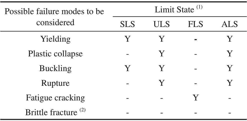
Table 1 Limit states linked to the failure mode
In such a case, limit states are associated not to the idealization used for the checks, i.e. the structural mechanics model, but with the goals of the project. Different failure modes may be relevant for various parts of the ship structure. For each failure mode, one or more limit states may be relevant.
Accounting for the particular marine structure under consideration, its mission profile and features as well as loading actions during its life,generally one limit state is the governing one and one corresponding failure mode should be especially assessed in the initial stages of a project.The structural models may be referring to the whole structure or to a part of it, appropriately identified in relation to the possibility of defining the acting loads and the boundary conditions.
Submerged thin-walled, stiffened cylinders are mostly loaded by external pressure and subject to collapse/buckling failure modes both,locally involving shell plating and stiffening members and globally collapsing the structure as a whole. Hence, SLS and ULS are the limit states of concern in concept design. Typically, effects like dynamic response and fatigue are checked at a later stage,where structural layout is already defined and issues are solved, likely with minor changes. It would be of extreme interest to anticipate such limit states in the preliminary design stage,but this is still quite far from the current industrial state of the art. The design philosophy underpinning the present study assumes that limit states are satisfied up to a certain depth independently, with no interaction between material yielding and structural component buckling. Such interaction is considered in a later design stage, where residual capacity is assessed.It is worth noting that actual definition of limit states may be different than that adopted in the present work.E.g. in DNV(2018), both the elastic and the elasto-plastic buckling pressures are in fact checked,leading to safety factors proposed for both elastic buckling pressure and admissible stresses lower than those adopted in the present study.
2.2 Design procedure and loading actions
Scantling design of submerged thin-walled stiffened cylinders is mainly an iterative process. Taking as a starting point the definition of the mission profile,the designer proposes a preliminary conceptual description of a possible design,then he/she carries out a series of estimates and eventually checks whether he/she satisfactorily dealt with the requirements,often needing to substantially modify the initial layout.Actually,the designer has to take a step back in case a requirement is not verified and,making new and more accurate assumptions,to iteratively re-work the calculations.
A database of dimensions,volume and weight characteristics of existing designs is often used at first to have initial estimates about buoyancy behaviour. Using mathematical models to parameterize the layout,feasibility studies are carried out to compare the results with the functional requirements and mission needs.Finally,feasibility studies are developed to a level of detail sufficient to check the overall design.
Focusing on the structural problem,the solution must be faced identifying the external loads to which the structure will be subjected.Typical loads for a submerged thin-walled,stiffened cylinder can be summarized in three items:
1)Load due to hydrostatic head,
3)Loads due to impulsive,shock events,if any.
In the presence of a pressure hull of a submarine,the significant loads are the static loads and the impulsive ones,while hydrodynamic effects are limited to the external hull.Hence,the maximum operating depth is by far the governing parameter when scantling a submerged structure. The pressure hull is the primary structural element of the entire vessel and,of course,it must be designed to withstand,with the necessary safety margins,the maximum operating depth(Figure 1).
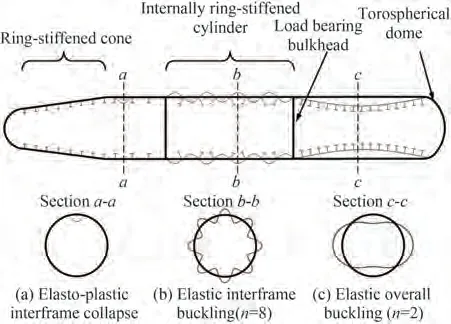
Figure 1 Typical pressure hull structure and buckling modes of a submarine(Dow et al.2012)
Especially at the initial stage of the design,it is not easy to predict whether the internal volume shall be completely available to the payload,or if a part of it shall be used e.g.as a reserve for buoyancy.Hence,in the frame of the iterative process leading to the hull scantling,it is not clear if the target should be minimizing the structural weight or maximizing the internal volume. Therefore, a compromise between the two parameters might be considered.
Remarkably,in the typical design strategies of submarines,it clearly appears that in most cases hull weight is not a ruling parameter of the whole design, as lack of buoyancy rarely occurs. Indeed, in most cases, hull weight is fundamental to reach the weight that balances buoyancy, allowing submarine to actually submerge.
Average density in this context is therefore a significant quantity being the parameter linking mass, including payload,and volume,i.e.payload space.The submarine's high overall density is not due to the density of its payload. In fact,most of the compartments of a submarine have a density like that of a surface warship; in addition, the battery rooms in diesel-electric submarines and the reactor room in nuclear submarines are close to the average density of seawater.Not even the amount of permanent ballast is sufficient to reach the overall density.The real explanation for the submarine’s high density lies in the fact that the submarine shall have a rather heavy hull structure.
Owing to this consideration, it is possible to state that the design of a submarine as well as that of other submerged structures can be oriented towards maximizing payload volume, rather than minimizing structural weight. Hence, the present paper focuses on the maximization of the payload volume within the iterative design process usually applied by submarine designers, even if the design procedure is able to highlight the impact of other meaningful characteristics of the structure and can be easily adapted towards other design goals.
2.3 Limit states and structural models
Because the main loading action on submerged structures is the external pressure, the resistant hull shall be checked upon four different failure modes corresponding to SLS and ULS,noted as:
The youngest is the least experienced and perhaps most protected of the children in a family. The youngest is also the child least likely to receive a financial inheritance in the days when the eldest40 son received the bulk of a father s estate. The youngest would consequently find it necessary to know how to fend for themselves in the world by marrying well or choosing a career.Return to place in story.
1) elasto-plastic collapse of the hull shell (yielding limit of the structure)
2)buckling of the shell between ring stiffeners
3)global buckling
4)annular tripping buckling of frames
2.3.1 Elasto-plastic(yielding)failure mode
A good starting point for the designer is to check the shell plating against yielding at the operational depth at first.This failure leads to plastic effects of axial-symmetric type. In order to check the elasto-plastic limit state, the axial and circumferential stresses may be calculated using the Pulos and Salerno formulations (Pulos and Salerno 1961). The following data and a cylindrical coordinate system, wherexis the cylinder axis, have been used in the present work as shown in Figure 2 and Figure 3. The failure mode is shown in Figure 1(a).
As a consequence, the following dimensionless parameters are then introduced:
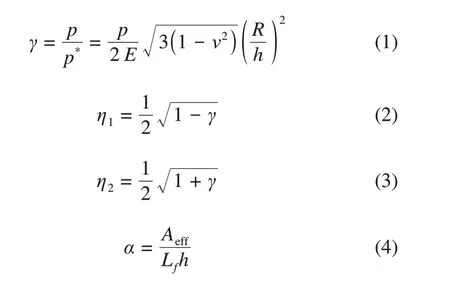
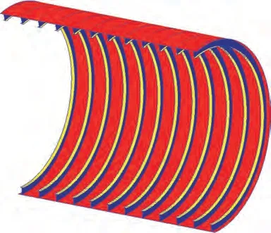
Figure 2 3D representation of ring-stiffened cylinder(half cut shown)
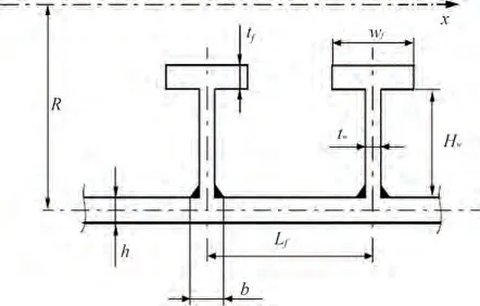
Figure 3 Scantling parameters according to Pulos and Salerno formulations(Pulos and Salerno 1961)
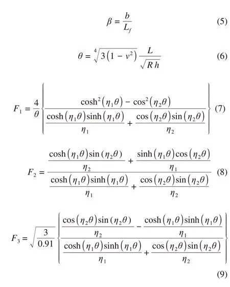
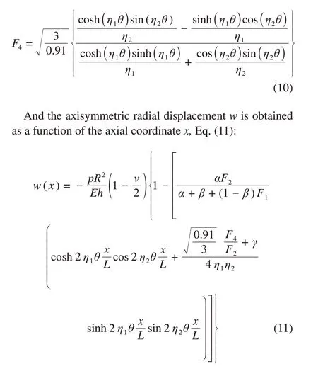
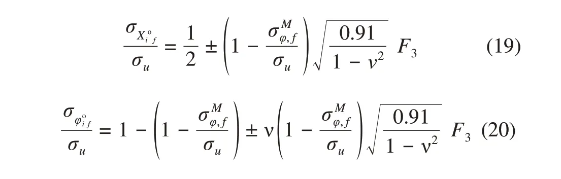
The radial displacement is calculated in way of frames,i.e.atx=0,and in between frames frame,i.e.atx=L/2.Substituting these values ofxinto Eq. (11), respectively, the following expressions are obtained:
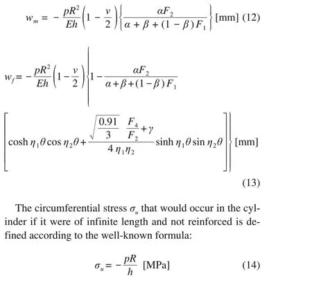
The axial stress due to the longitudinal bending moment is defined by the following equation:
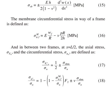
where the subscriptiindicates the internal surface of the external shell plating of the vessel and the subscriptoindicates the external surface,respectively.
Finally, the axial stress,σXf, and the circumferential stress,σφfare defined in way of each frame as:
The Pulos and Salerno’s equations allow correcting the ideal case of an infinite long perfect cylinder under pressure into that of a cylindrical shell in between two transverse frames, considering suitable boundary conditions.The calculated acting stresses shall be combined to be used in a convenient failure criterion, which for the yielding of metallic materials can be assumed to be the well-known von Mises’one.
2.3.2 Buckling failure modes
In structural engineering, buckling is the sudden change in shape(deformation)occurring on a structural element when the load, generally due to compression or shear, reaches a critical level.
The consequence of this phenomenon is the loss of stiffness of the element with resulting large deformations and possible structural failures. The phenomenon can concern the structure as a whole,and in this case,it is called global buckling (Figure 1(c)), or it can be more localized on a specific component like an elementary plate panel or stiffening members surrounding it, and in this case it is denoted as local buckling(Figure 1(b)).
In a thin-walled,stiffened cylinder,local buckling generally affects the shell plating between two or more transverse frames,involving the formation of irregular lobes on the plating.These lobes take the form of alternating concavity and convexity both along a generatrix and around a directrix of the cylinder.
R.von Mises dealt extensively with the problem,initially by studying the case of a ribbed cylinder subject to uniform and infinitely long radial pressure, later von Mises(1929)by expanding the analysis to circular section of submarines.The hypotheses in this latter case envisaged modelling the hull as a cylindrical shell with stiffeners, having its ends simply supported and subjected to uniform external radial pressure and axial compressive load due to the presence of the closing bottoms,as comprehensively reported in von Mises(1929).
The various buckling checks applied in the present work are reported in the following.
2.3.2.1 General analytical buckling checks
In this study,the dissertation by R.von Mises has been used,which includes simplifications to formulate a definition of the critical pressurepcras a function of the geometry of the shell plating, the elastic characteristics of the material and the number of circumferential lobes that are originated in case of buckling collapse(von Mises 1929):
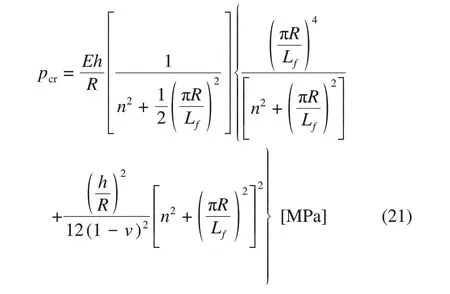
wherenis the number of circumferential lobes (integer which makes the equation minimal).
Since the number of half-wavesnis initially unknown,the formulation requires several attempts, repeating the calculation for a certain range ofn(assumed as integer value),until a minimum value ofpcris identified.
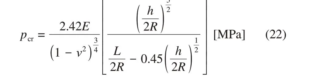
An estimate of the critical pressure independent of the number of lobes, could be obtained according to Windenburg and Trilling(1934)for guidance:
2.3.2.2 Global buckling
Global buckling is characterized by a particular modal shape that involves a portion of the hull between two reinforced transverse structures (reinforced frames and/or bulkheads). This phenomenon involves the structure as a whole and, depending on the slenderness, its occurrence is usually a sign of a sudden and catastrophic global collapse.
Global critical load of the cylinder section is influenced by the boundary conditions imposed by the frames at its ends,namely by their moment of inertia,as well as by the circular shape imperfection,besides the length/diameter ratio of the cylinder (the onset of the phenomenon is favoured by very slender hulls).
Global buckling can be evaluated using the equation formulated by Bryant(1954):
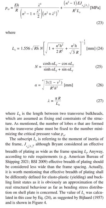
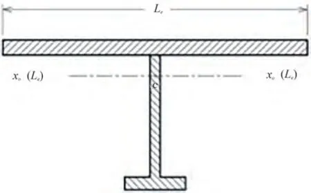
Figure 4 Cross section to be considered for the buckling of the annular frame,being xo(Le)the transversal axis at the centroid including the frame cross section plus the effective width as calculated by Eq.(24)
2.3.2.3 Annular tripping buckling
An annular beam with insufficient stiffness, subject to an external radial load,can collapse due to buckling of the elastic equilibrium at stress well lower than the elastic limit of the material as Figure 5.
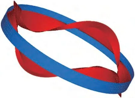
Figure 5 Buckling of the annular frame
Tokugawa(1929)developed a formula for calculating the critical buckling pressurepcrdue to the ovalization of the frame of a submarine, referring to an infinitely long functionally graded cylindrical vessel. More recently, Shiomitsu and Yanagihara (2020) proposed and validated against FE analysis a novel analytical approach to evaluate the tripping buckling of ring-stiffened cylindrical shells under external pressure.In the present work,authors adopted this latter method to evaluate the elastic stability of the frame,which has been successfully applied in several previous works.The equation is quite complex and cannot be reported in the present paper for the sake of shortness.Anyway,interested reader can find the details in the cited references and use of different checking formulae do not impair the scantling procedure validity.
2.3.3 Hoop stress
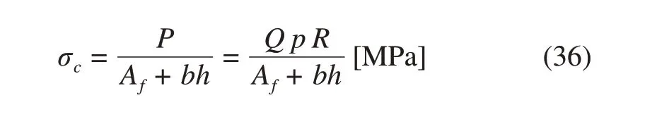
Although the stiffening frames and the welded plating are subjected to the same circumferential strain due to compatibility reason,the circumferential stress acting in the frames is different than that of the plating, since the stress in the plating is also affected by the axial strain.Basically,a complex three-dimensional stress field is generated locally in way of the connection between stiffeners and shell resulting into a stress components lag. In accordance with the theory of von Sander and Gunther (1921), the radial loadqdistributed on the frame is proportional to the external pressurepaccording to the relationship:
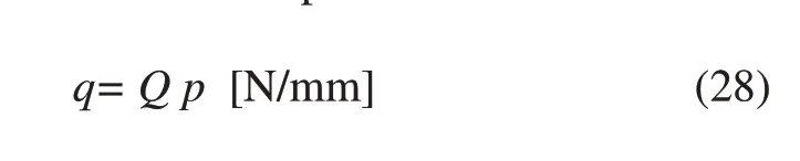
in whichQhas the dimensions of a length and it can be seen as the width of the shell plating in way of the frame supporting the effect of external pressure on the bottom ends.
The widthQ,in the context of von Sander and Gunther’s theory,is given by the following expression:
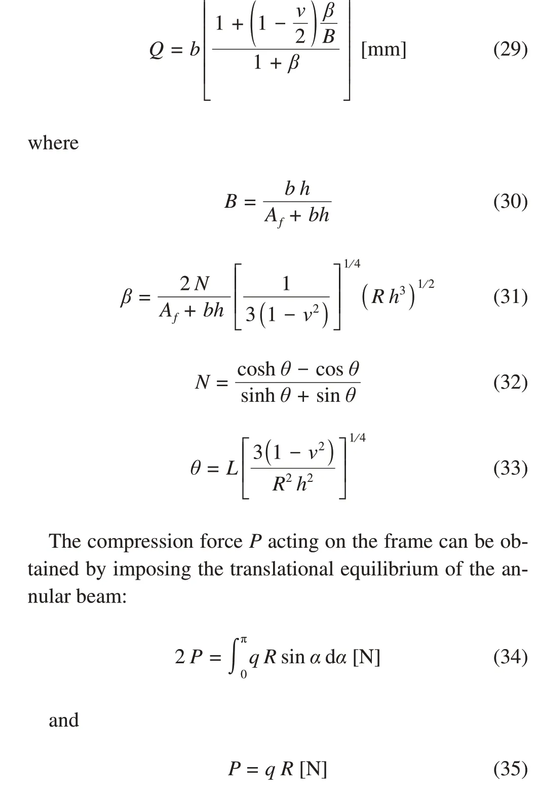
Ultimately,the compressive(hoop)stress in the frame is:
Alternatively, the hoop stress can be evaluated according to the Pulos and Salerno theory already examined for the yielding of the shell plating.In this case,σcmatches with the stressσФfalready defined in section 2.3.1:
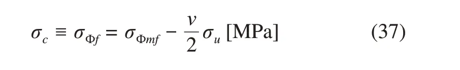
whereσuis the circumferential(negative)membrane stress.
2.4 Definition of limit states
After describing the main failure modes of submerged thin-walled stiffened cylinders, a practical problem arises when setting up a design philosophy encompassing them as a whole.The designer’s objective is in fact to check the structure against all the potential limit states and corresponding failure modes,considering all their interactions as far as possible.
Being the main scantling parameter the maximum operating depth,a design depthHdesmay be fixed initially referring to yielding failure mode.Hence,the design depth identifies the occurrence of yielding in a single (local) point of shell plating or of any stiffening member.
In practice,there is still a residual structural capacity following the initiation of yielding locally, where the probability of structural collapse increases as the depth increases beyond the design depth. The safety factors used in limit state assessment should be defined considering the consequences of the occurrence of a certain failure mode and the residual capacity beyond such limit.E.g.,local buckling of plating likely leads to local yielding only, while global buckling may easily lead to overall structural collapse, involving sudden yielding of wide areas of the structure and a larger safety factor is therefore recommended to keep sufficient margins against complete collapse.
Geometrical imperfections, namely shell imperfection and frames tilt,also play a key role affecting the ultimate strength of the submarine.Such imperfections can be generated during the manufacturing process (e.g. due to thermal effects)or while in service(e.g.by impact loads).Although analytical formulations may account for the effect of imperfections for certain limit states, authors decided to implicitly include such effects within safety coefficients since the proposed approach is intended to be applied in concept/preliminary design phases to obtain basic scantling of the structure with limited engineering efforts.
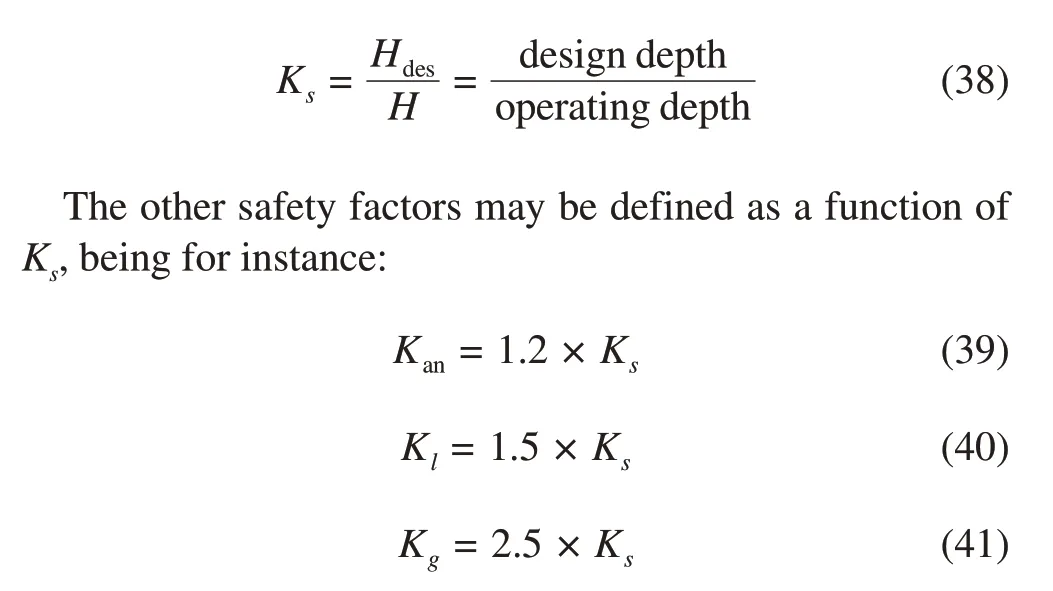
In the light of the above, safety factors can be defined establishing a relationship between the design pressure and the pressure triggering various failure phenomena. In this case study,the following safety factors have been defined:
•Ksthe safety factor against yield stress (elasto-plastic limit state);
•Kanthe safety factor against the hydrostatic pressure to be used for the verification of annular buckling of frames;
•Klthe safety factor against the hydrostatic pressure to be used for the verification of local buckling;
•Kgthe safety factor against the load hydrostatic pressure to be used for the verification of global buckling.
Dynamic and impulsive loads may be additionally accounted for by duly calibrating the a.m.safety factors.
Accordingly,Ksis defined as:
It is not easy to determine reasonable safety factor values,and certainly a study dedicated to this perplexing problem would be welcome. However, this is beyond the aim of this paper as it encompasses calibration against experimental and field data, including fabrication and service issues, as well as calibration against comprehensive numerical and experimental analyses, including formal safety assessment and risk analysis. In this paper, the following ranges have been used following widespread discussions,upon the experience of renowned European shipyards:
•Ks=1.50÷2.50;
•Kan=1.80÷3;
•Kl=2.25÷3.75;
•Kg=3.75÷6.25.
Moreover,as mentioned,the occurrence of material yielding may lead to a sudden plastic buckling collapse highly impairing the residual capacity of the structure beyond yielding. These phenomena should be well assessed by the designer when defining the factorKs.
In summary, the proposed scantling design approach is based on well-proved analytical formulations to check the structural scantling with respect to a number of limit states and failure modes.Hence,a new verification framework is outlined where,after carefully defining set of‘boundary conditions’, a rational design strategy is established aimed at optimizing the performances of the construction in terms e.g. of usable internal volume, weight per unit length, shell plating thickness below the workability limit, etc.. This is obtained simply by systematically modifying the structural layout,scanning all the relatively few feasible structural layouts satisfying the problem constraints and selecting the best trade-off option, taking advantage of a computation tool developed on purpose.
3 Case study
As a typical case of study,a submarine hull has been exemplarily selected with the purpose to optimize the payload volume as earlier mentioned. Therefore, the distance between the transverse frames is optimized to be able to reduce as much as possible the height of the web's frame,allowing the widest internal space.A computational code has been developed on purpose in VBA(Visual Basic for Applications)environment.
Two different hulls have been elaborated, starting from a reference layout presented in Table 2 and derived from typical submarines.The structural dimensions of the former case study were derived from openly available data of the SSK(the United States Navy hull classification symbol for the Submarine killer) type submarine, while the latter is a much larger ocean vessel.
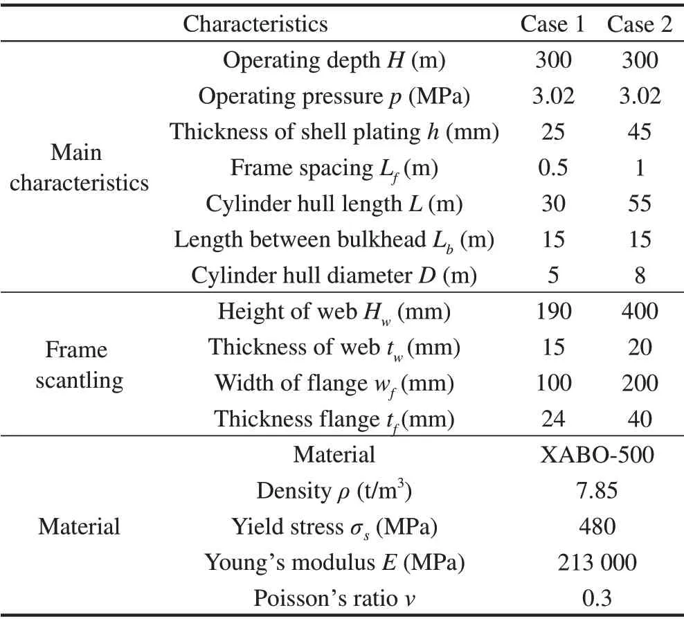
Table 2 Characteristics of the two case studies
The safety factors adopted in this work are discussed in the following:they were selected to obtain a reasonable balance between safety and maximum operating depth, thus providing a practical example of the design procedure application.It is worth noting that neither the external diameter of the submarine nor the length of the compartment have been varied in the alternative configurations because of the following reasons:
•The hull diameter is usually a dimension that cannot be anymore modified at the scantling design stage, being derived by mission requirements and other issues investigated in earlier design stages.On the other hand,if instead of a fixed value the structural designer was provided with a range of realistic diameters, the algorithm proposed in the following is so slender that it could be quickly run different times to systematically analyse various diameter values and then obtained results can be eventually compared. This could represent an interesting approach when,instead of fixing the hull external diameter,the internal‘net diameter’inside frames is representing the governing scantling parameter. In this case, the designer would be oriented to select the minimum external diameter allowing a minimum required net internal diameter. This option is quite unlikely,but the proposed method can easily allow exploring even varying external diameters, e.g. by considering step variations of this input parameter(or even others if necessary).
•The distance between bulkheads, unlike ships, is hardly dictated by structural considerations.On the contrary,this is often a requirement deriving from considerations about survivability in case of a breach. The presence of a transversal bulkhead often leads to very critical stress concentrations in the connection area with the shell plating;hence the designer would avoid such complications,also because the benefit led by the presence of the bulkhead on the global buckling strength is usually quite limited.Based on current experience, in order to increase the global buckling strength of the submarine,it is better to directly modify parameters such as plate thickness and frame spacings and layout, instead of introducing transversal bulkheads. In a few words, if for some reasons, other than structural ones,transversal bulkheads are present, the designer should proceed with the currently proposed scantling strategy of the compartment having a fixed length.On the other hand,if a too long compartment would not meet the minimum global buckling requirements,splitting the compartment by adding new transversal bulkheads is not a good idea,in general,while selecting an allowable layout as an outcome of the currently proposed scantling procedure is recommended.
In some cases,king-frames,also called deep-frames,are used at certain positions.They are frames having increased height and scantling with respect to ordinary ones. From a structural point of view,they behave like a transverse bulkhead.Hence,their role is to reduce the length of a compartment,in order to increase the global buckling critical pressure. In the proposed method, the length of the compartment is implicitly included in the procedure. So, it is a designer's choice to decide if the compartment shall be restrained by a transversal bulkhead or by a deep-frame depending on functional needs.
Considering the criticalities arising by inserting a rather stiff transversal component in term of stress concentrations on the local connecting elements and shell plating, nowadays designers tend to exclude such elements in structural layouts, unless it is decided that bulkheads are necessary to increase the survivability of the crew in case of flooding or the unit is too long to prevent global buckling with a standard layout. In conclusion, a deep-frame leads to the same critical issues in term of stress concentrations as a bulkhead, although it does not separate compartments in case of flooding. For this reason, deep frames are quite uncommon in modern structural layouts.
3.1 Elasto-plastic limit state
About the elasto-plastic limit state, considering the linear dependency between loads and stresses up to yielding,the safety factor has been accounted for considering an admissible stress, obtained by scaling the yielding stress byKs. Therefore, while checking the structure against elastoplastic collapse, the static head is calculated considering the operative depth and the resulting stresses checked upon the admissible stress.
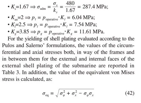
The maximum value of the equivalent von Mises stress is compared to the allowable stress of the material as defined above (σamm=287.4 MPa). The limit state is hence verified by a margin of about 6%-7% with respect to the admissible value.
In addition,the hoop stress is calculated using Eqs.(34)-(35)for the two cases study as reported in Table 4.
The maximum value of the hoop stress is compared tothe allowable stress of the material (σamm=287.4 MPa) and the limit state is hence verified.
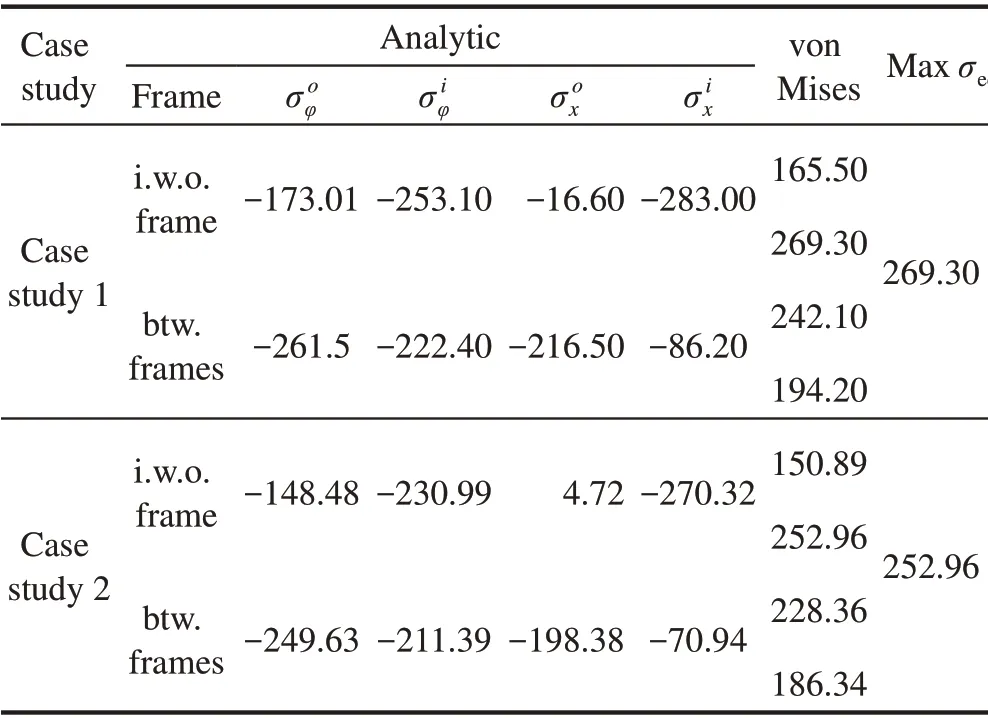
Table 3 Yielding of shell plating evaluation (MPa)
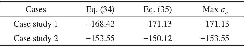
Table 4 Hoop stress evaluation σc (MPa)
3.2 Buckling failure modes
The critical pressurepcrleading to buckling shell plating between frames,estimated through the R.von Mises’s equation, Eq. (19), has been estimated for a sufficient number of circumferential lobesnfor each case study, as reported in Table 5.
The lower pressure in Table 5 indicates that the critical pressure according to the R. von Mises formulation ispcr=14.75 MPa for case study 1, andpcr=14.72 MPa forcase study 2. Owing the adopted safety factors and subsequent operating pressure,pl=3.02 MPa,it can be concluded that the check is verified by a rather large margin.
Table 5 Critical load for the shell between ring stiffeners according to von Mises’s equation
The same limit state has been evaluated applying the Windenburg and Trilling formulation defined by Eq. (20). For the case study 1,the critical pressure ispcr=15.10 MPa and for case study 2 ispcr= 14.90 MPa. In the analysed cases,the Windenburg and Trilling formula does not affect the accuracy of the calculation as it deviates from the R.von Mises results only by about 2%.
In the case studies, the length of the compartment between two watertight bulkheads is defined asLb=15 m.The third check,i.e.global buckling,is determined through the Bryant’s equation, Eq. (21). Thepcris calculated for various values of the number of circumferential lobes as reported in Table 6.
The lowest pressure in Table 6 indicates the critical pressure; therefore, according to Bryant’s formulation for the case study 1 the critical pressure ispcr=11.75 MPa and forcase study 2 ispcr= 30.80 MPa, rather different considering this limit state depends mainly on frame spacingLfand hull radiusR. They compare favourably with the pressure load as defined according to the safety factor adopted:pg=11.61 MPa.This limit state is thus verified by a margin relatively small for the case study 1 (9.7%) and a larger margin for case study 2.
Table 6 Critical load for the global buckling according to Bryant’s equation
Finally, the critical pressurepcr= 9.27 MPa andpcr=18.25 MPa,respectively for case study 1 and case study 2,are calculated using the equation defined by Tokugawa,Eq. 23, to check the annular buckling pressure.Again, the limit state is verified with ample margins,beingpl=6.06 MPa.
Given the case studies,it is worth noting that yielding is the limit state that governs the scantling process of the present layouts,being the margins on such limit state the minimum one among those considered.
3.3 Analysis of alternative configurations
The internal volume,intended as the volume free from internal structures stiffening the shell plating i.e.the cylindrical volume inside the flanges of the beams,is a fundamental parameter for the design of a submarine and the stiffening members sizes are constrained by space needs deriving from functional requirements. Furthermore, the structural weight is a rather large fraction of the total weight of the unit,and it must be sufficient to allow the submarine to dive,providing the unit with an average density equal to the saltwater one,which guarantees an indifferent equilibrium condition. At the same time, the structural weight must comply with an upper limit to allow enough payload. Hence, a relatively narrow weight range of structures is normally accounted for in design.
It is therefore necessary, in the initial stages of design, to select the shell plating and stiffening members’s cantling,allowing the maximum internal volume but still satisfying the structural limit states as well as keeping the steel weight under control. It is proposed to optimize the distance between the transverse frames, so as to be able to reduce as much as possible the height of the web’s frame, hence maximizing the internal volume of the stiffened cylinder.
With this goal in mind, a computational code has been developed on purpose in VBA (Visual Basic for Applications)environment,able to consider all the limit states previously illustrated in full detail to obtain the best scantling design.
The following assumption was made aiming at maximizing the structural weight and increasing the submarine overall density:the value of flange and web thicknesses were considered constant,being 20 and 15 mm respectively,and set equal to an assumed constructive constraint due to the maximum workability of the steel plate by the shipyard.Different assumptions can be made in case increasing the structural weight is considered marginal,yet leaving the proposed design process still effective.
Conversely,the following quantities have been defined as varying within certain ranges, considering usual engineering practice:
• The thickness of the external plating of the submarine ranges from 20 to 60 mm for the case study 1 and from 20 mm to 80 mm for case study 2;
•Cross section area of the reinforcement varies from 20 to 180 cm2for case study 1 and from 80 to 250 cm2for case study 2;
•The frame spacing varies from 350 to 1 200 mm for all cases(based on an integer number of subdivisions within a given compartment lengthLb).
The maximum flange width was defined as a function of the frame spacing accounting for the construction and welding allowances. It is assumed that the width of the flange does not exceed 40% of the frame spacing as shown in Figure 6.Such constraint also leads to the definition of rather heavy frames,however,maximizing internal volumes.Such choice is questionable but can be easily varied without affecting the effectiveness of the proposed procedure.
Figure 6 Definition of the flange width
Moreover, cross-sections shapes were verified against class rule limits regarding e.g. flange breadth vs. flange thickness ratiobf/tfand web height vs. web thickness ratioHw/tw.Anyway, since the second order area moment of the beam cross section only plays a minor role in providing adequate structural stiffness being on the contrary the crosssection area the governing parameter, the designer is oriented towards quite ‘fat’ cross sections, in order to increase internal bulk of the vessel and rules’shape limit s are easily satisfied.
The proposed numerical approach for the selection of the optimal scantling design is conceptually constituted by two iterative “FOR” cycles, aiming at combining all the possible structural layouts, namely the frame spacing, with all the plating thickness in a specified range,to be decided by the user, in order to comply with the manufacturing constrains of the shipyard.
where
•i: number of subdivisions of the compartments, equal to the number of transverse frames between two bulkheads plus one.The frame spacing will result as the length of the compartment divided by the number of subdivisions. The developed code can additionally consider user-defined values for minimum and maximum number of subdivisions;
•j: thickness of the hull plating, increased progressively. The range of the thickness is a discrete parameter that can be varied, along with the step of increment set by default equal to 1.0 mm;
Hence, a genericCi,jlayout configuration is generated combining the frame spacing with the shell plating thickness.Then, a solution-searching algorithm is introduced to identify theCi,jlayout configuration showing minimum area of the cross section of the frame and able to comply with the four failure modes previously described:namely the plate yielding,annular buckling of frames,local buckling of plating,global buckling of the compartment.
In the present work, besides a simple iterative approach scanning all possible solutions that proved to be also quite valuable,authors tested three more advanced solution algorithms aiming at minimizing the cross-section area of frames,namely GRG non-linear, Simplex LP and Genetic. It was found that GRG proved to be the best compromise concerning computational cost, being a loose convergence more than enough for the intended purposes (indeed, ±1 mm2is by far sufficient).
When generating the frame cross section looking for the internal volume maximization, the workability limit of the shipyard is used to define the(maximum)thickness for both web and flange set respectively to 15 and 20 mm,in the test cases.Those code parameters can easily be varied(and systematically checked) in case different constrains emerged in the design stage.The widest possible flange leads to minimum web height of the frame, complying with the defined fabrication constraint. Consequently, given the cross-section area (without the effective breadth) of the frame, the web height can be easily derived as:
where
•Hw:web height
•AT:cross section area without effective breadth;
•bf: flange width, defined as the maximum fraction of the frame spacing(constraint);
•tf: maximum thickness of flange, according to shipyard working limits;
•tw: maximum thickness of web, according to shipyard working limits.
The second area momentJx0(lf)is then calculated,considering the effective breadth of plating, and used in the verification of the global buckling.
Having assessed eachCi,jlayout configuration against limit states, only a subset of combinations of the parametersi,joffer an admissible scantling design, which can be now considered.
The first plot obtained considering the results of the analyses is shown in Figure 7, for case 1 and in Figure 8 for case 2.The plot relates,given the frame spacing,the minimum thickness of the shell plating to the minimum area of the reinforcement satisfying the limit state requirements.The vertical line identifies the point at which at least one of the limit states is no longer satisfied,meaning that below a certain thickness of the plating the required beam cross section diverges.Hence,it is not possible to find a suitable solution unless the cross-section area becomes infinite.
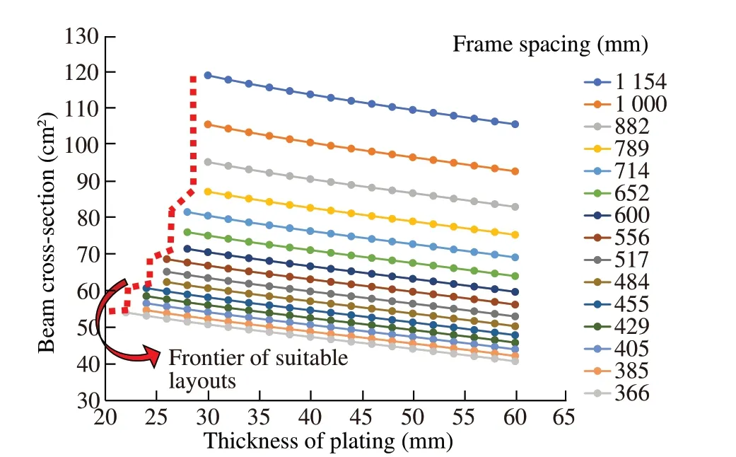
Figure 7 Frame spacing vs shell plating thickness and cross section area of the frame for case study 1
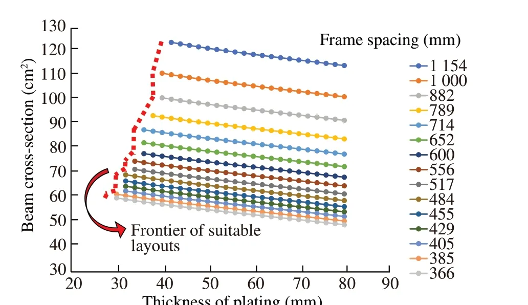
Figure 8 Frame spacing vs shell plating thickness and cross section area of the frame for case study 2
It is worth noting that,with the proposed design strategy and safety margins,global buckling is in the very most cases the limit state that governs the structural verification.
The charts provide the designer with a broad comprehension of the admissible layouts: the shell plating thickness is the key parameter,since,on the one hand,a thick plating represents a challenging task concerning workability for the shipyard,and,on the other hand,the weight of the whole structure is mainly due to the shell plating contribution. Therefore, it is possible to combine the desired plate thickness with the frame spacing and the minimum required crosssection area of the frames.Anyway,this plot does not contain any suitable information about the weight of the structure and the bulk of the transverse frames.
The second summarizing plot, proposed in Figure 9 and Figure 10, relates the frame spacing with the shell plating thickness and the frame height. It is worth noting that all curves, as long as the verification criteria are satisfied, are almost superimposed for a wide range of frame spacing,and only the widest analysed spacings when combined with thin plating lead to increase, minimally, the web’s height. This suggests that the frame spacing value has a minimal impact in the scantling.E.g.in case 1,for a plating of 30 mm,varying the spacing from 366 to 652 mm only leads to a web height increment of 8 mm,which becomes 35 mm for a spacing of 1 154 mm.
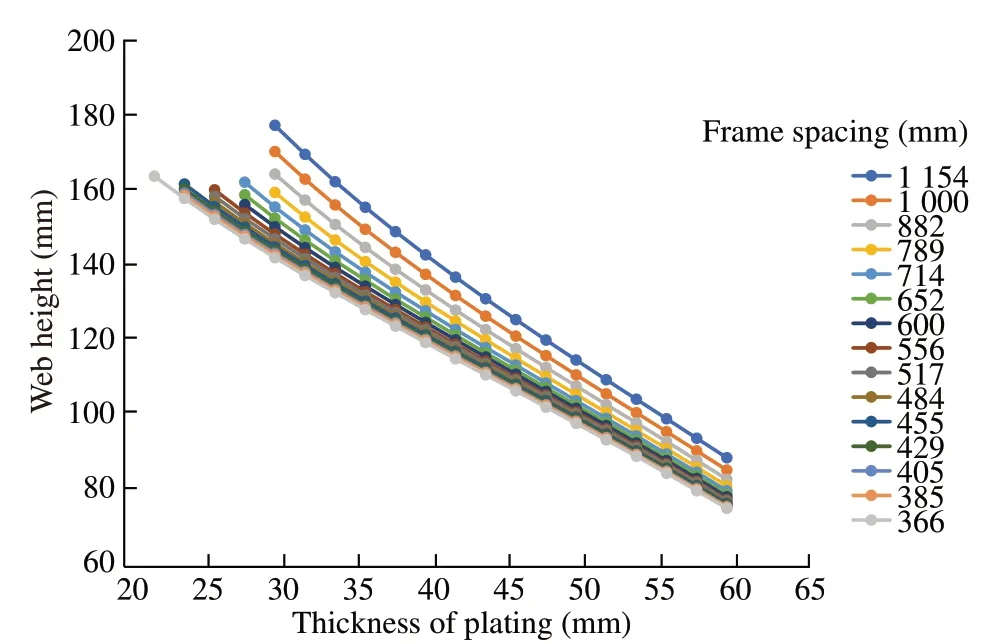
Figure 9 Frame spacing vs. shell plating thickness and height of stiffeners for case study 1
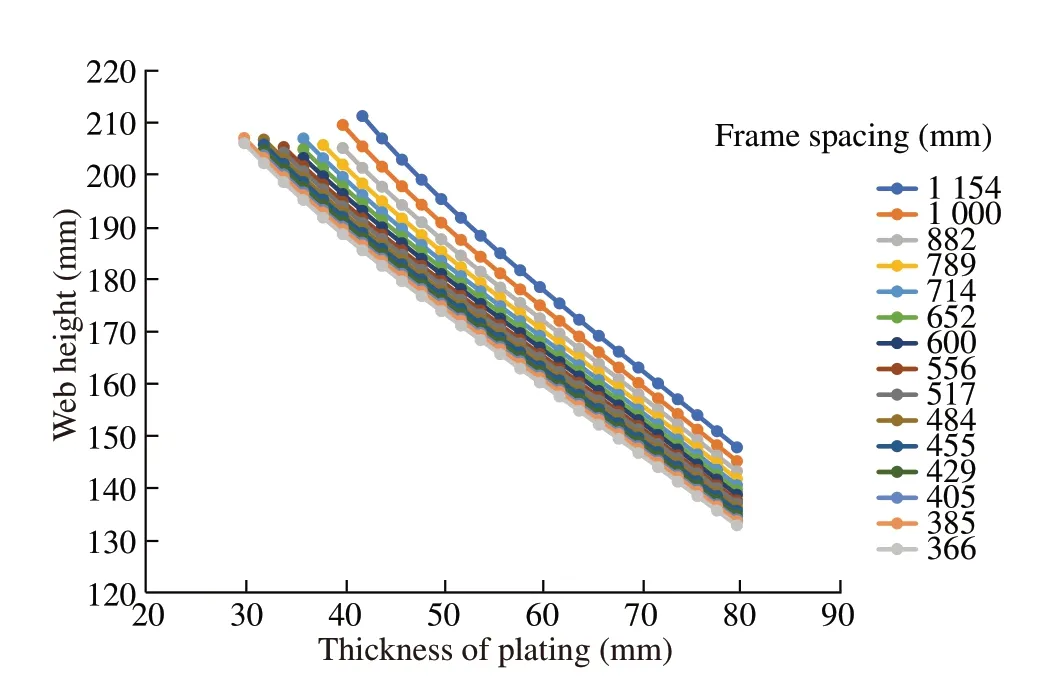
Figure 10 Frame spacing vs. shell plating thickness and height of stiffeners for case study 2
This fact opens for a significant degree of freedom in the selection of the frame spacing, which can be defined for specific targets in terms of weight and building costs.This,basically, represents an in or out problem: if the limit states are satisfied,all the transverse frames will have similar minimum height,disregarding the frame spacing.Otherwise,if for a certain plating thickness the requirements are not met at a given spacing, it is not possible to find a scantling solution by increasing the web height,and a new frame interval shall be considered.
Finally, the weight of the whole structure, expressed in terms of weight per unit length by dividing the weight of plating plus the frames by the length of the compartment,is related to the thickness of plating as shown in Figure 11 and Figure 12.This represents a fundamental design parameter for a submarine,as a fixed range of weight of the structure is usually required,in order to obtain the correct average density to allow the submarine to dive.
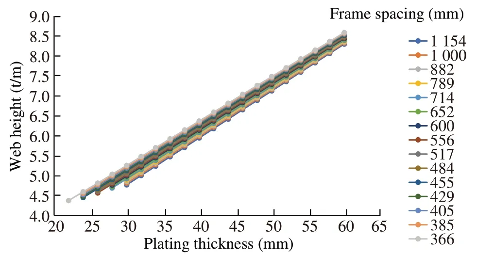
Figure 11 weight per unit length related to the thickness of plating for case study 1
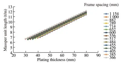
Figure 12 weight per unit length related to the thickness of plating for case study 2
4 Proposed scantling procedure
As a result of the previous analyses, a workflow is proposed to define the scantling layout of the submerged thinwalled stiffened cylinder.In the following,it is reported the analysis based on case 2 of the previous section:as a selected example,a target weight per unit length ranging between 8.0 to 9.0 t/m is assumed,accounting for hydrostatic reasons.
• From hydrostatic considerations, the range of the weight per unit length of the structure is hence fixed.Of course,a wider range represents a loose constraint,allowing more admissible configurations. From Figure 13(a), a corresponding range of thickness of plating is identified.The black line at the bottom of the curves represents the boundary for each given frame spacing where the limit states are no longer satisfied for a certain thickness of plating, irrespective of the frame considered. Hence, a mass per unit length lower than approximately 6.5 t/m is not possible,unless different constraints are considered for the shape of the cross section of the frame (e.g. thinner web or faceplate being equal the cross-section area).
• From Figure 13(b), the corresponding range of web heights is identified, where the plot previously obtained in Figure 9 is matched with the current weight limits,and available configurations highlighted.At this stage, the designer can make a decision based on the constraint about the internal volume within frames, as the minimum web height is available only for a limited set of frame spacing that complies with the limit states taken into account, in the target range of weight per unit length.
By the way, in the present case, the problem showed a relatively poor sensitivity towards web height,being all solutions included in a range of about 20 mm(172-192 mm):hence,designer is more responsive on focusing on the combination of the plating thickness vs.frame spacing.Especially considering the manufacturing process in the shipyard,widest spacing limiting the number of elements to be welded and a thinner shell plating facilitating the strakes butt-welding is selected unless even minimal variations of the internal volumes represent a strict requirement.
The proposed chart represents in fact an overview of admissible structural layouts complying with both, adopted limit states and structural weight limits. At this stage, the designer can compare, within a limited number of feasible solutions,the influence of plating thickness,web height and frame spacing,in order to address his/her final decision for the following steps of the design process.
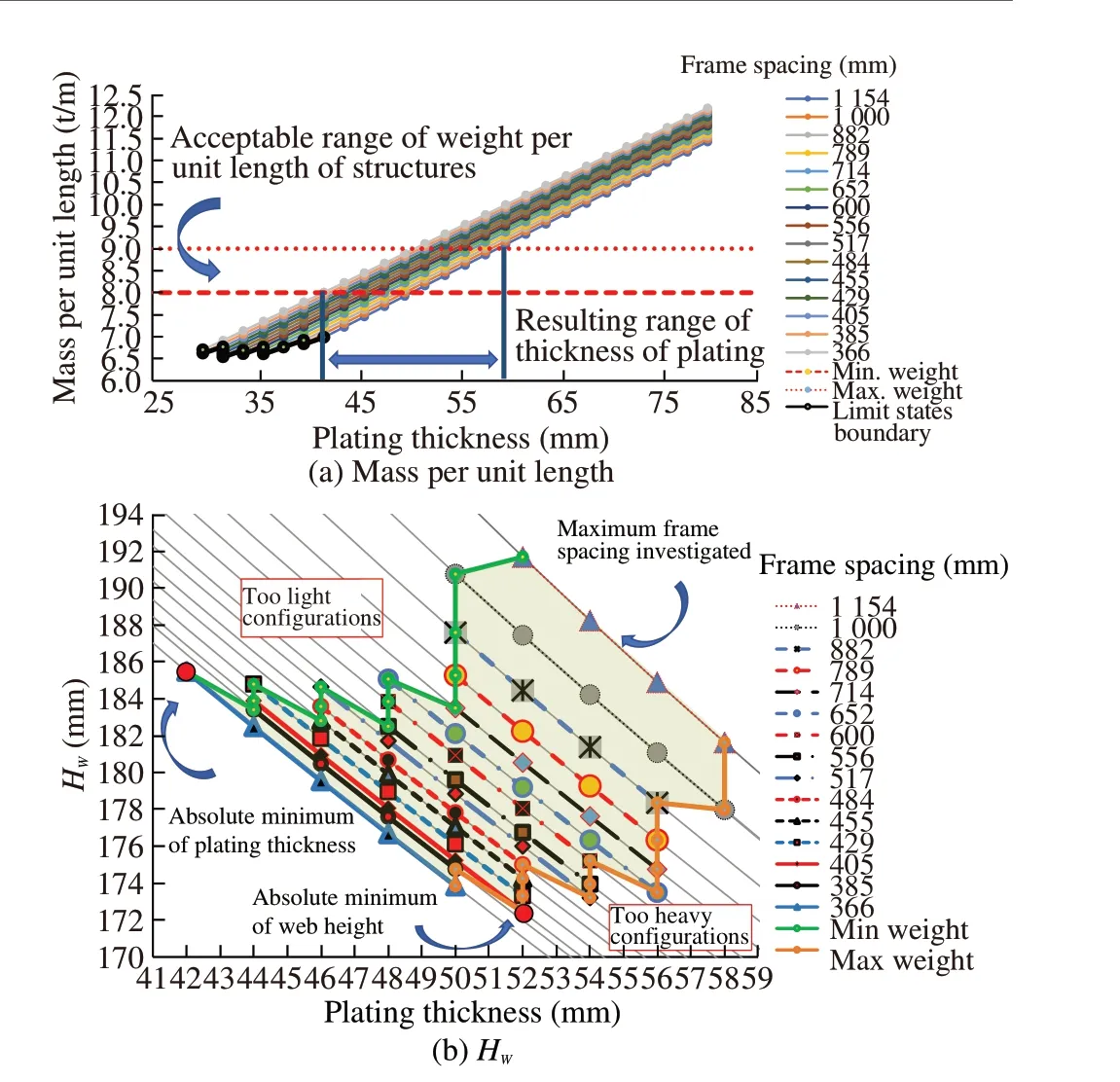
Figure 13 Scantling procedure scheme
It is possible to summarize the proposed scantling design procedure in Figure 14.
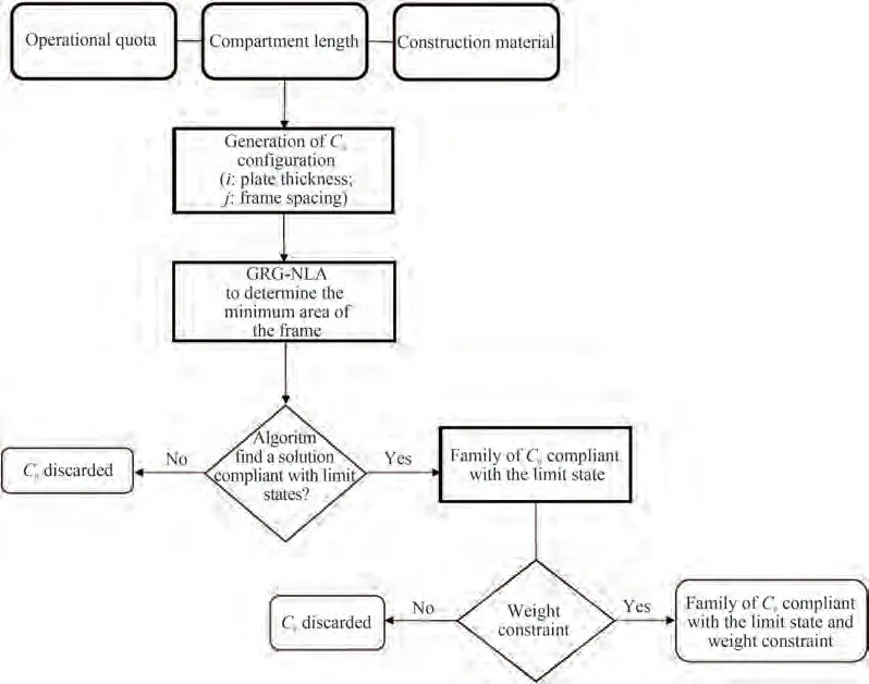
Figure 14 Scantling design procedure flow chart
5 Conclusions
Following the idea and principles already put forward in Aguiari et al.(2021)for the scantling design of naval vessels,this paper proposes a concept-design scantling procedure of submerged thin-walled stiffened cylinders aimed at obtaining the optimal internal payload volume. However, the proposed procedure may be well adapted to other different target cases and objectives as highlighted in this paper.
The underpinning idea of the proposed procedure stands on two main issues:(i)goal based design and(ii)limit state design. The former design approach intends to define the criteria and the strategies aimed at fulfilling the mission profile and operational needs of the hull structure while the latter one outlines the constraints imposed by structural robustness,safety and construction processes.
In short,the general problem of defining the structural layout and the relevant scantling of a submerged thin-walled stiffened cylinder is formulated as a set of limit state equations, including suitable safety margins and depending on a number of scantling design variables such as spacings,spans,thicknesses, stiffener cross section profiles, etc.Along with the limit state equations,addressing structural robustness and safety,additional constraints are considered,limiting the variation of the variables within ranges and dictated by construction requirements and sound engineering judgment.
It comes out that, differently from what intuitively perceived, the general problem of defining the scantling layout of a submerged thin-walled stiffened cylinder is rather wholly constrained and therefore complex mathematical optimization algorithms are not deemed useful nor effective,despite they are nowadays available and broadly applied in scientific literature.Indeed,it appeared that,in conceptualdesign phases, limit states of such a regular axisymmetric structure are analytically defined in sufficient detail using a set of scantling variables, ranging within limited ranges and which have been interlinked each other.
A very comprehensive literature survey as well as a deep analysis of available analytical models to assess limit states and failure modes of thin-walled immersed cylinders was carried out in order to select best options for the purpose.Results of the selection has been summarized in this paper to allow further developments in future studies.Noticeably,mostly numerical analyses are reported in recent literature, while sound and robust analytical scantling approaches seem going forgotten despite they still prove very valuable and effective.
Starting from construction constraints, this paper proposes a scantling strategy that maximizes the internal volume available for the payload,minimizing the height of the frame,that is a reasonable engineering choice considering the captioned geometry,leaving no other realistic possibilities.
The input data, as illustrated in section 4, is linked to the weight per unit length of the cylinder according to hydrostatic considerations,in particular to reach an average density suitable for the operating profile of a submarine. Based on this,a strategy is proposed that takes into account all the variables of the structural layout starting from the spacing of frames and the thickness of the shell plating, allowing to provide a rational framework to the designer.
Eventually,it is underlined that a simple iterative approach has been implemented in a software code developed on purpose,allowing creating various guidance charts helping designer to compare various design solutions and to modify the goals of the analysis.Such a tool may be easily incorporated into a design synthesis model for ship design as it uses basic variables derived from fundamentals of the naval architecture design process. Additionally, as a by-product of the developed VBA code, the FEM model input of the optimal scantling solution obtained by the analytical procedure is automatically created for design refinement and final assessment.
The proposed scantling process highlights that there is no need of complex algorithms if sound engineering judgment is applied in setting down rationally the hull scantling problem. Namely, if all actual constraints are duly considered,the scantling design appears to be satisfactorily faced as a rational parametric design process and may successfully lead to the optimal scantling among feasible but sometimes counterintuitive solutions. Numerical optimization algorithms are not necessary if the problem is governed by relatively few independent variables, varying in a limited range and often assuming in practice only a selection of few values.Numerical approaches,i.e.FEA,may indeed induce deviations from optimal feasible design beside requiring unnecessary computation and engineering resources. Nevertheless,rational scan of feasible solutions needs a systematic approach based on a computer-coded procedure to be effectively implemented nowadays. It is worth noting that the proposed scantling procedure,implemented in a numerical user-friendly tool, provides results in very limited time and systematic review of various alternatives is likewise possible by simply modifying the variables’ranges or basic input data.
FundingSupported by the Italian Ministry of Defense-Segredifesa,in collaboration with Fincantieri under Grant of the ASAMS (Aspetti specialistici e approccio metodologico per progettazione di sottomarini di ultima generazione)project(2019-2022).
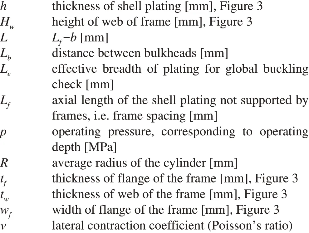
Nomenclature
Aefftransversal area of frame[mm2]
bthickness of web’s frame plus welds[mm],Figure 3
Dcylinder hull diameter[mm]
EYoung’s modulus[MPa]
Hoperating depth, maximum depth at which the submarine is assumed to dive[m]
Hdesdesign depth, at which yielding limit state is not satisfied in one point of the structure[m]
杂志排行

Journal of Marine Science and Application的其它文章
- Numerical Investigation of the Effect of Surface Roughness on the Viscous Resistance Components of Surface Ships
- Deconvolved Beamforming Using the Chebyshev Weighting Method
- Optimization of Gas Turbine Exhaust Volute Flow Loss
- Overview of Moving Particle Semi-implicit Techniques for Hydrodynamic Problems in Ocean Engineering
- Numerical and Experimental Investigation of the Aero-Hydrodynamic Effect on the Behavior of a High-Speed Catamaran in Calm Water
- Surface Modification of AH36 Steel Using ENi-P-nano TiO2 Composite Coatings Through ANN-Based Modelling and Prediction