Improvement of the spreading effect of atmospheric pressure microplasma jet treatment through shielding-gas-controlled focusing
2022-08-29LiLV吕栎JianhangCHEN陈剑航JiahaoWANG汪加豪ShengquanWANG王圣泉MengLI李蒙DeyuTU涂德浴LipingSHI时礼平andTaoWANG王涛
Li LV (吕栎), Jianhang CHEN (陈剑航), Jiahao WANG (汪加豪),Shengquan WANG (王圣泉), Meng LI (李蒙),3, Deyu TU (涂德浴),Liping SHI (时礼平),3,* and Tao WANG (王涛),3,4,*
1 Anhui Province Engineering Laboratory of Intelligent Demolition Equipment, Maanshan 243032,People’s Republic of China
2 School of Mechanical Engineering, Anhui University of Technology, Maanshan 243032, People’s Republic of China
3 Anhui Province Key Laboratory of Special Heavy Load Robot, Anhui University of Technology,Maanshan 243032, People’s Republic of China
4 Key Laboratory of Green Fabrication and Surface Technology of Advanced Metal Materials,Ministry of Education, Anhui University of Technology, Maanshan 243032, People’s Republic of China
Abstract The spreading effect of atmospheric pressure microplasma jets (APμPJ) on the surface of materials will increase the etching area, and controlling the diameter of the jet can improve the precision of surface treatment.In this work,a two-dimensional axisymmetric simulation model is established to analyze the effect of nitrogen (N2) shielding gas on helium (He) from gas dynamics. In addition, by etching the polyethylene terephthalate film, the relationship between the etching effect and aerodynamic analysis is verified. The simulation results are similar to the experimental results,indicating that N2 shielding gas has a focusing effect which is related to the N2 flow rate, distance difference between the inner and outer tubes, and outer tube nozzle diameter. It is hoped that the results of this work can provide a certain reference for the use of shielding gas to control the jet flow of APμPJ.
Keywords: microplasma jet, nitrogen shielding gas, focusing effect, gas dynamic
1. Introduction
Atmospheric pressure cold microplasma jet(APμPJ)is a new plasma-generation technology which is free from the limitation of vacuum environments [1]. APμPJ has low temperature, low cost, and rich reactive species, etc, and has been widely used in sterilization[2-4],surface modification[5,6],biomedicine [7, 8], combustion assistance [9, 10], and other fields.APμPJ can treat complex surfaces,and can modify the surface of a material without affecting the properties of the material itself, providing new solutions and possibilities for the development of surface treatments.
In the actual plasma discharge process, the plasma jet ejected from the nozzle will increase the diameter of the jet,and,as the gas flow rate increases,the jet diameter will further increase [11, 12]. For high-precision surfaces, the increase in jet diameter will increase the line width on the processed surface, resulting in an actual processing area larger than the expected one, which directly affects the final processing accuracy.
In order to solve these problems, various methods based on limiting the diffusion of the plasma jet on the surface have been proposed, and their feasibility has been proved. Khan et al[13]adopted the idea of solid shielding and used a quartz tube to reduce the influence of ambient gas on the plasma jet.The results showed that the method was practical and the diameter of the plasma jet was significantly improved.Onyshchenko et al [14] also proposed a solid shielding method to achieve the focusing of an atmospheric pressure low-temperature plasma jet.An additional plate was added at the bottom of the capillary to suppress the lateral diffusion of the jet. As the distance between the baffle and the surface decreased, the extent of the hydrophilic area on the polyethylene terephthalate (PET) surface increased. In order to explore the cause of this phenomenon, the molar concentration distribution of plasma flow at different distances between the baffle and flat surface was simulated. Numerical simulation showed that the smaller the distance between the baffle and the flat surface,the higher the molar concentration of the plasma jet and the wider the distribution range on the flat surface.Schmidt-Bleker et al[15]used a mixture of nitrogen(N2) and oxygen (O2) as the shielding gas curtain to investigate the reaction mechanism of the atmospheric pressure argon cold plasma jet, and obtained better experimental results and simulation data. Kapaldo et al [16] also adopted the idea of shielding gas when studying the influence of atmospheric pressure plasma on cancer cells. Their results proved that the influence of different components of shielding gas on cancer cells was controllable. Shirafuji [17], Pinchuk[18], and Prakash [19] also used experiments to prove that ambient gas could affect the diffusion of plasma jets in the surrounding air, and that shielding gas could inhibit the diffusion of plasma jets. Akishev et al [20] studied the transversal spreading of a plasma jet at its impinging the surface.The results showed that the plasma jet could be symmetrically and stably distributed on the stationary surface. However,when the surface rotated,it was difficult for the plasma jets to keep stable and distribute symmetrically due to the movement of the gas flow.
The addition of shielding gas to achieve a focusing effect of the plasma jet has become a new technique to suppress the diffusion effect of the plasma jet on a substrate. However, to our knowledge,the effect of shielding gas on the beam effect or the plasma itself has not been investigated systemically.Therefore,a fluid focusing method is proposed in this work to achieve this effect on the plasma plume, and the influence of various parameters on the jet is systematically studied,as well as the influence of the gas flow on the plasma itself.Previous results have shown that the main reason for the expansion is due to the interaction between the plasma jet and the material,as well as the lateral ion waves generated by the charged particles on the wall.
In this work, a fluid dynamic simulation of neutral gas flow is used to illustrate the effect of shielding gas on the jet ejection. Onyshchenko et al [14] showed that the simulation results of neutral gas fluid dynamics were in good agreement with the actual modified beam spot effect through experiments and simulation studies. The gas flow has a general importance in fluid mechanics owing to the development of turbulence,gas mixing in diffusion flame,gas flow dynamics,and many other applications. The plasma jet discharge at atmospheric gas pressure may contain combined characteristics such as the flow of working gas and electrostatic force among plasma particles [21, 22]. The fluid mechanical property of gas flow may have influence on the discharge phenomena and the electrostatic collective force of plasma may produce or modify the gas flow [23, 24]. Therefore, the simulation method can be used to investigate the focusing effect of the neutral gas. Considering the stability and low cost of N2, this work mainly uses N2as the shielding gas. In this work, a two-dimensional axisymmetric model is established through the COMSOL Multi-physics simulation software, and the focusing mechanism of the shielding gas is analyzed through the computational fluid dynamics (CFD)module and the dilute substance transfer module. By changing the process parameters, the velocity change and concentration distribution of the working gas were analyzed to explore the characteristics of the APμPJ, and experimental verification was carried out. It is hoped that the research results in this work can provide a reference for the use of shielding gas to realize the precision and controllable treatment of APμPJ.
2. Simulation model and experimental equipment
2.1. Simulation model
In this work, the simulation model adopts a two-dimensional axisymmetric structure. The model size is AB=BR=QR=AQ=50 mm, AC=25 mm, CD=45 mm, AE=0.4 mm, AF=0.6 mm, AG=1 mm, AH=2 mm, MN=OP=0.5 mm, NP=8 mm, IJ=0.2 mm, JK=0.4 mm, and KL=1 mm.AQ is the axis of symmetry,BR and QR are set as open boundaries,and CD simulates a substrate surface.AE is the radius of the inner tube, EF is the wall thickness of the inner tube; AG is the radius of the outer tube, and GH is the wall thickness of the outer tube. The model is composed of a concentric tube structure;the inner tube is fed with working gas He,and the outer tube is fed with shielding gas N2. The distance between the outlet port and the surface is set to 2 mm. MNPO simulates a copper foil electrode wrapped on the outer tube.Three two-dimensional transversals and a three-dimensional section are marked in figure 1. Transverse line 1 represents the gas junction, transverse line 2 represents the central axis,transverse line 3 represents the substrate, and section 1 represents the entire substrate surface.The speed of natural flow is set to 0.025 m s-1. The remaining boundaries are walls, and the operating temperature in the entire simulation is set to 25 °C.
2.2. Neutral gas flow dynamics model

Figure 1.Two-dimensional axisymmetric geometric model.
The state in any flow field needs to satisfy the mass conservation equation (continuity equation) and momentum conservation equation (Navier-Stokes equation). That is, the increase in the mass of the fluid element per unit time is equal to the mass flowing into the fluid element at the same time,and the rate of change of momentum in the fluid element with respect to time is equal to the sum of the external force vector acting on the fluid element.
The continuity equation is as follows:
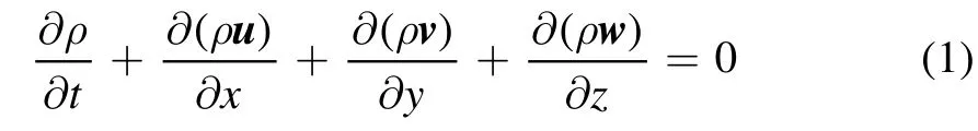
where

In the formula,ρis the density;tis the time;andu,v,ware the components of the velocity vector in the x, y, and z directions,respectively.If the fluid is in a stable state and the densityρdoes not change with time, the equation can be simplified to
The Navier-Stokes equation is as follows:

where

In the formula,pis the static pressure;xiandxjare the coordinate points;uiandujare the shear viscosity coefficients in the directions ofxiandxj;δijis the Knecker;τijis the stress tensor;cjis the fluid length;ρgiandFiare the gravitational volume force and other volume forces,respectively;the subscripts i,j indicate the i, j substances.
The convection-diffusion equation is as follows:

where

Figure 2. Schematic diagram of APμPJ generator.
In the formula,ciis the molar concentration of particle i;uis the mass average velocity of the gas mixture;Jiis the mass flux of particle i relative to the mass average velocity;Riis the net productivity of particle i;Diis the diffusion coefficient of gas.
2.3. Simulation hypothesis

(1) Generally speaking, the dimensionless Reynolds number (Re) is used to distinguish between laminar and turbulent flow[25].The Reynolds number is calculated as follows:In the formula, V is the average gas velocity; D is the inner diameter of the nozzle;v is the kinematic viscosity of the gas flow;ρis the gas density; μ is the gas viscosity. In the simulation process of this work, it is assumed that the flow field is always in a laminar state.
(2) It is assumed that the plasma forms a free jet in the atmosphere without considering the chemical reactions between the plasma and other components in the atmosphere, and ignoring the influence of secondary factors such as mass force, volume force, and electromagnetic force of the plasma.
(3) He/O2working gas was used in the experiment,and the O2content was 1%.To simplify the simulation,pure He was used instead.
2.4. Experimental materials and setup
2.4.1. Materials. PET is one of the most common thermoplastic polymers. It has excellent properties such as chemical resistance, corrosion resistance, dimensional stability, and easy recycling, which has been widely used in the surface modification of polymers [26]. The PET film used in the experiment is a rectangular block with dimensions10 mm×10 mm ×5 mm.

Figure 3.He molar concentration distributions under different N2 flow rates;(a)-(h)correspond to N2 of 0,100,200,300,400,500,600,and 700 sccm, respectively.
2.4.2.Experimental setup. The APμPJ generator used in the experiment is shown in figure 2, which includes discharge,gas circuit, test, and control systems. Detailed information about the experimental setup is available in our previous work [27].
The working gas is high-purity helium (He (99.999%))and high-purity oxygen (O2(99.999%)). Due to the electronegativity of O2, free electrons in the space will be adsorbed, resulting in suppression of discharge and reduced jet length. The total flow of working gas is 400 sccm, of which the flow of He is 396 sccm, and the remaining 1% is O2. Due to the chemical inertness and low cost of N2, highpurity nitrogen(N2(99.99%))is selected as the shielding gas,and the flow rate is controlled at 0-700 sccm. Through the calculation of Reynolds number, it can be known that the working gas and shielding gas are in laminar flow.
3. Results and discussions
3.1. Effect of N2 flow rate
The N2flow rate is one of the main influencing parameters of the shielding gas on the plasma jet.As shown in figure 3,it is the effect of different N2flow rates on the He molar concentration distribution in the range of 0-700 sccm,and the He concentration gradually decreases from the center to the outside. When no shielding gas is introduced, it can be observed from figure 3(a) that after He is ejected from the outlet,there is an obvious diffusion phenomenon in the space,with diffusion even into the N2tube. As the N2flow rate increases, the surrounding N2gas mixes (through laminar convective diffusion)into the He jet when He flows out of the tube, resulting in a decrease in the mole fraction of He[28, 29]. There is an obvious non-concentration area below the N2outlet,and the size of this area is positively correlated with the N2flow rate, indicating that N2forms a layer of air curtain which restricts the exchange of He and ambient gases.At the same time, the N2shielding gas not only limits the distribution of the high He concentration area, but also weakens the He concentration in the central region, and the weakening degree is positively correlated with the N2flow rate.
Although the N2flow rate has a greater effect on the He concentration of the central axis, it has less effect on the He velocity of the central axis. The influence of velocity is mainly concentrated at the intersection of gas,and the change trend of velocity of the central axis is relatively stable. The concentration of He remained stable in the tube, the velocity decreased after being ejected from the outlet, and the concentration reached the minimum after reaching the substrate.The higher the N2flow rate, the lower the concentration at that location.
Due to the low density of He,the buoyancy in the air also has a certain influence [30, 31]. However, the velocity changes in different processes.He enters the tube from the inlet,and the speed increases rapidly and then remains stable. The velocity increases slightly near the outlet,decreases rapidly after leaving the outlet, and returns to zero when He reaches the substrate.These results can be drawn from figure 4(c).
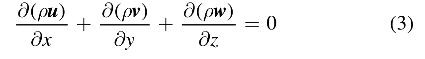
In order to analyze the effect of the intersection of the two gases,the concentration and velocity changes at the intersection of the gases are plotted in figures 5 and 6. It can be seen from figure 5 that in the absence of shielding gas, the He concentration is always kept close to 1 mol m-3.When the shielding gas is introduced, the He concentration at the gas junction changes significantly compared to that without shielding gas. In the vicinity of the outlet,the He concentration is low,and gradually leaves the outlet, and the concentration gradually increases and reaches the maximum on the substrate.Under different N2flow rates,the concentration change process is similar,but the larger the flow rate, the smaller the He concentration at the same position.Compared to the concentration at the gas junction,the velocity trends at the gas junction are similar,with or without the shielding gas. After leaving the outlet, the velocity increases continuously, the increase trend of the velocity is the largest at the 0 and 1.6 mm positions,and the velocity decreases rapidly to 0 near the substrate. Between 0 and 1.6 mm, the larger the N2flow rate,the faster the velocity increase,which is mainly due to the result of the larger N2velocity at the gas junction.

Figure 4.Velocity distributions with the N2 flow rate of(a)0 sccm and(b)700 sccm;(c)velocity and concentration curve at the center axis with N2 flow rate of 700 sccm.
Figure 5.He molar concentration variation curve at gas junction.

Figure 6.He velocity variation curve at gas junction.
After the He hits the substrate surface, it diffuses into a ring-shaped concentration distribution on the substrate, as shown in figure 7(a). In the central area of the jet, the concentration of He is the largest, diffuses outward, and the concentration gradually decreases. Figure 7 shows the molar concentration distribution of He on the substrate under the action of different N2flow rates, of which the top curve corresponds to figure 7(a), which is the result without shielding gas. Combining the two figures 7(a) and (b), it can be found that the areas with high He concentration are mainly concentrated in a 10 mm diameter range.Breden et al[32]has also showed that He plasma jets will extend a certain radial distance outward after contacting the target surface, and eventually mix into the air;the farther the radial distance,the lower the mole fraction concentration, which is consistent with the simulation results in this paper. When the N2flow rate is less than 400 sccm, the concentration at 5 mm has a slight upward trend,which may be due to the strong collision between the working gas He and the shielding gas N2at this position.
To sum up,within the scope of this study,the increase of shielding gas N2flow rate will further limit the distribution of the high-concentration He region.

Figure 7. (a) He molar concentration distribution on the substrate without N2 shielding gas, and (b) concentration change curve on the substrate under different N2 flow rates.

Figure 8. Influence of distance difference x on He molar concentration distribution without shielding gas. (a) x=+1, (b) x=+0.5, (c)x=0, (d) x=-0.5, and (e) x=-1.
After comprehensive consideration, in the following study of distance difference x and outlet diameter D,with the participation of N2shielding gas, the N2flow rate is selected to be 300 sccm.
3.2.Influence of distance difference x between inner and outer tubes
The distance difference between the inner and outer tubes is represented by x,where the inner tube is the reference and the outer tube is extended as positive. First, in order to exclude the influence of structure on the results, figure 8 plots the He molar concentration distribution under each structure without shielding gas. In figure 8, under each structure, the diffusion degree of He concentration is similar,and it is difficult to find the difference.
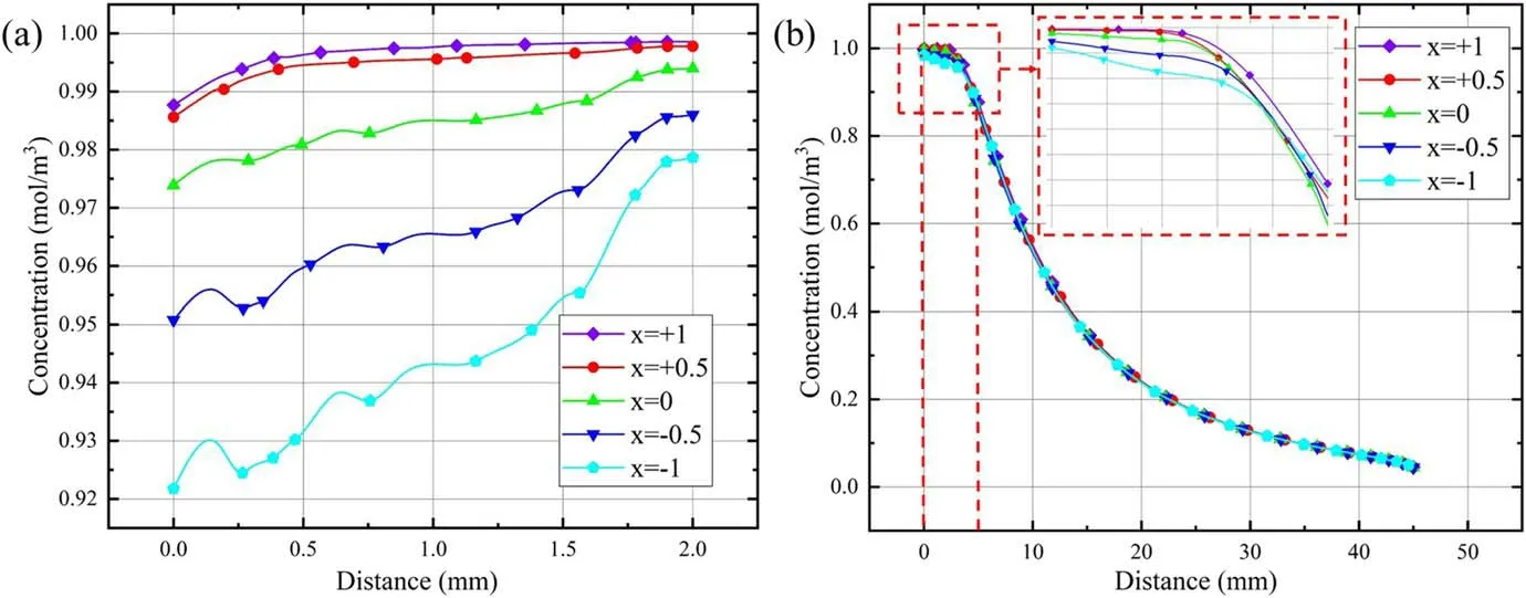
Figure 9.Molar distribution of He at different positions under the influence of distance x without shielding gas(a)at gas junction,and(b)on the substrate.

Figure 10.Influence of distance difference x on He molar concentration distribution with N2 shielding gas of 300 sccm. (a) x=+1, (b)x=+0.5, (c) x=0, (d) x=-0.5, and (e) x=-1.
The difference visible to the naked eye may be that there is a small lightening of the dark red area below the concentric tubes as x goes from large to small. The influence of the structure on the He concentration distribution can be clearly seen from figure 9.The outer tube protrudes outward relative to the inner tube, limiting the outward diffusion of the high-concentration He, which is similar to the result in Onyshchenko’s work[14].The greater the distance difference x, the greater the limiting effect. However, the He concentration at the gas junction is always greater than 0.92 mol m-3. The concentration distribution difference on the substrate is mainly concentrated in the 0-5 mm range, as shown in figure 9(b),and the concentration curves almost overlap.In general,the distance difference x can have a certain influence on the results without shielding gas, but the influence is limited and can be ignored.
As shown in figure 10, when the N2shielding gas is introduced,it is obvious that the diffusion of He concentration in the space is significantly reduced, and the concentration is only higher in the central axis region. Compared with the distance difference x=0,when x>0,the outer tube restricts the outward diffusion of N2and intensifies the inward diffusion.As the distance difference x increases,the concentrationfree area increases toward the center axis. When x<0, the space for N2to diffuse outwards increases, resulting in the increase of the non-concentration area outwards. Due to the change of structure,the change of He concentration at the gas junction is more complicated after the shielding gas is introduced.However,from the results at the end point(on the substrate) at the gas junction, it can be seen that as x decreases, the He concentration on the substrate increases, as shown in figure 11(a). This conclusion is consistent with the results in figure 11(b). As the distance difference x increases,the outward diffusion of N2is restricted, the interaction between N2and He is intensified,and the He concentration is reduced.

Figure 11.Molar distribution of He at different positions under the influence of distance x with shielding gas(a)at gas junction,and(b)on the substrate.

Figure 12.He concentration distribution under the conical structure. (a) No N2, (b) N2 flow rate of 300 sccm, (1) D=1.4 mm, (2) D=1.6 mm, (3) D=1.8 mm, (4) D=2.0 mm.
3.3. Effect of outlet diameter of outer tube
In the research of existing plasma jet devices, a structure composed of a special-shaped nozzle or a syringe and glass tube is used to realize the gas shielding of the plasma jet[33,34].In this work,the shape of the outlet is controlled by changing the outlet diameter D of the casing, and the influence of N2shielding gas under different structures is analyzed. Considering the low practicability of the complex model and the complicated simulation process, the casing shapes in this section are mainly divided into trumpet,cylindrical, and conical shapes. The difference in shape is limited to the diameter D of the outlet nozzle.
As shown in figure 12, when the shielding gas is not introduced,the high concentration of He mainly concentrates on the outlet of the outer tube and the vicinity of the central axis, and diffuses on the substrate only after hitting the substrate. After injecting N2, it can be observed that the concentration of He decreases significantly after the injection,and there is a clear gap with the inner wall of the outer tube.It can be seen from figure 13(a)that the larger the diameter,the stronger the diffusion effect of He and the smaller the concentration on the substrate;this change is only effective in the high-concentration region. The concentration distribution on the substrate was similar after the shielding gas was introduced.However,when D=1.8 mm at the outlet of the inner tube, the concentration at this position is the largest.

Figure 13. He concentration distribution on the substrate under the conical structure. (a) No N2, (b) N2 flow rate of 300 sccm.

Figure 14.He concentration distribution under the flared structure. (a) No N2, (b) N2 flow rate of 300 sccm, (1) D=2.0 mm, (2) D=3.0 mm, (3) D=4.0 mm, (4) D=5.0 mm.

Figure 15.He concentration distribution on the substrate under the flared structure. (a) No N2, (b) N2 flow rate of 300 sccm.

Figure 16.Observation and measurement PET etching results. The corresponding etching conditions are the influence of N2 flow, no shielding gas. (a) 2D morphology, (b) 3D morphology.
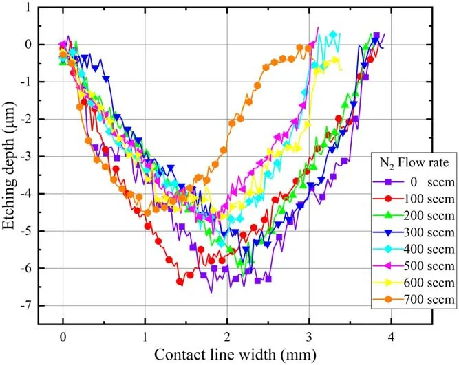
Figure 17.Etching depth change at the center position under the influence of N2 flow rate.

Figure 18.Etching results with the influence of N2 flow rate.
There is a clear difference between the results of the conical structure and the flared structure without shielding gas. In the flared structure, after He is ejected from the inner tube,it is mainly concentrated near the central axis but a small part of the gas still flows into the outer tube, as shown in figure 14.When the shielding gas is introduced,the diffusion of this small part of He disappears. It can be seen from figure 15 that with the increase of the diameter D, the He concentration in the high-concentration region on the substrate gradually decreases, and the maximum concentration when D=2 mm is much larger than that in other cases.When N2is introduced, the region of the high-concentration He is restricted, the concentration on the substrate decreases,and the smaller the diameter, the more the concentration decreases. It is shown that the larger the outlet diameter, the worse the inhibitory effect of the N2shielding gas.
4. Experimental verification
The preceding simulation study is limited to gas dynamic analysis; in order to prove the feasibility of the simulation results,PET etching experiments are carried out. The surface etching morphology was observed through the two-dimensional (2D)and three-dimensional (3D) etching results, as shown in figures 16(a) and (b). As presented in figure 16(a), the depth variation path is drawn from the central position so as to obtain the change curve of etching depth. Furthermore, a systematic analysis of the contact line width and the maximum etch depth was carried out.
It can be found from figure 17 that when there is no N2shielding gas,the contact line width and etching depth remain relatively large, and when N2is introduced, the contact line width and etching depth gradually decrease. Among them, in the experiment, when the N2flow rate reaches 700 sccm, the contact line width and etching depth are significantly reduced,and this result can be obtained in figure 18. The weakening effect on the He intensity increases with increasing N2flow rate, resulting in a high concentration of He only kept just below the outlet orifice.There are obvious contact line widths and etching depths near the position with high He concentration, and the contact line widths and etching depths gradually decrease when the He concentration decreases in the central region.

Figure 19.Etching depth change at the center position under the influence of distance difference x.
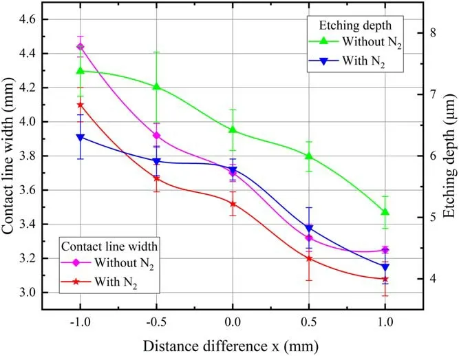
Figure 20.Etching results with the influence of distance difference x.
It can be seen from this simulation that as the distance difference x increases,the distance between the outer tube and the substrate as well as the He concentration in the central area gradually decrease. Referring to figure 19, when the distance difference x is the same, the contact line width and etching depth are obviously reduced after the shielding gas is introduced. By comparing the cases with and without shielding gas in figure 20, it is found that the contact line width decreases gradually with the increase of x, and increases slightly when x=1.The etch depth decreases to the smallest extent when x=0, and the decrease is similar in other cases. In general, the regions with larger etching depth are mainly concentrated in the position with higher He concentration.

Figure 21.Etching depth change at the center position under the influence of nozzle outlet diameter D=2, 3, 4, and 5 mm.

Figure 22.Etching results with the influence of nozzle outlet diameter D=2, 3, 4, and 5 mm.
Consistent with the simulation, when exploring the influence of N2under different structures, the cylindrical shape is used as a reference, and the experimental results under the conical shape and the trumpet shape are discussed.It can be seen from figures 21 and 22 that the maximum contact line width and etching depth occur when the nozzle outlet diameter D is 4 mm without the presence of N2.Although in the presence of N2shielding gas,the contact line width and etching depth are smaller than those without N2,the actual influence law is more complicated.The diameter of the outlet is greater than 2 mm. In the absence of N2, the larger the diameter of the outlet,the larger the diffusion space of the working gas and the larger diffusion space after the jet flows out of the outlet,resulting in a larger actual contact line width and etching depth. However, when the outlet diameter was increased to 3 mm after adding N2shielding gas, the increase of the contact line width was smaller. When the outlet diameter increases to 4 mm, the contact line width reaches the maximum value.As the outlet diameter increases to 3 mm, the inhibitory effect of N2on the jet increases,resulting in a smaller etching depth.When the outlet diameter is 4 mm, the outward diffusion space of N2increases, the inhibition effect on the jet intensity is reduced, and the etching depth of the jet reaches the maximum value. After that, due to more air entering the jet, both the contact line width and etching depth decrease, but the contact line width varies more.

Figure 23.Etching depth change at the center position under the influence of nozzle outlet diameter D=1.4, 1.6, 1.8, and 2 mm.

Figure 24.Etching results with the influence of nozzle outlet diameter D=1.4, 1.6, 1.8, and 2 mm.
In the experiments above, the suppression of the plasma jet by the shielding gas resulted in a reduction in the actual contact line width and etch depth. However, different experimental results appeared when the outlet diameter is too small.In the absence of N2, the contact line width decreases gradually with the decrease of the outlet diameter, but when the outlet diameter is less than 1.6 mm, the contact line width tends to fluctuate steadily, as presented in figure 23 and figure 24. The outlet diameter decreases from 2 to 1.8 mm,and the etching depth decreases sharply.After that,the outlet diameter continues to decrease,and the etching depth changes slowly, but there is still a decreasing trend. After N2is introduced,the contact line width fluctuates around 2.4 mm as the outlet diameter decreases. When the outlet diameter is 1.6 mm,the contact line width with N2is larger than that without N2. In the presence of N2, as the outlet diameter decreases, the etching depth decreases slightly, and finally tends to be stable.However, it has been found through experiments that when the diameter of the outlet is less than 2 mm,the etching depth with N2is greater than that without N2. The reason may be that the outlet diameter is too small and the flow rate becomes the main influencing factor, which requires further research and demonstration. In general, under the same conditions, the contact line width of the trumpet shape is larger than that of the conical shape, consistent with Taiana’s work [35].
5. Discussions
In this work, the He concentration distribution under various conditions with or without N2shielding gas is mainly considered,and the ultimate goal is to limit the processing area of the plasma jet. In addition to suppressing the transverse ion waves of the plasma, N2shielding gas can also achieve a shielding effect on the ambient gas (air). Kawasaki et al [36]explored the effects of the surrounding gas on the plasmainduced downward liquid flow and found that a higher nitrogen-oxygen concentration ratio in the surrounding gas can reduce the oxidation reaction during the plasma radiation process. When the plasma jet diffuses in the air, a large number of air molecules enter the atom and ion stream,which will cause a large number of charged particles and excited state substances, such as metastable states, to be lost in the interaction between the He plasma jet and the ambient gas.By shielding the influence of ambient gas by N2, the loss of charged particles can be greatly reduced [37].
In this work, the focusing effect of the N2shielding gas and the structural parameters of the outer tube on the working gas are analyzed from the perspective of aerodynamics through simulation. Since the effects of the thermal field and discharge process in the plasma jet are not considered in the simulation, the final etching effect cannot be strictly described.In order to illustrate the feasibility of the simulation,PET etching experiments were carried out corresponding to the simulation parameters. The area with larger working gas concentration corresponds to the area with larger contact line width and etching depth in the experiment, and the change rule is similar after changing the parameters. It is shown that the simulation in this paper has certain feasibility. In the follow-up research,adding the thermal and electric fields into the simulation model is proposed as a way to simulate the plasma jet more accurately.
6. Conclusion
In this study,a two-dimensional axisymmetric simulation model of plasma jet gas dynamics is established to simulate the influence of N2flow rate,distance difference x,and outer tube nozzle diameter D on the molar concentration distribution of working gas He with or without N2shielding gas.The focusing effect of N2is analyzed by the simulation results, and the experimental results are verified. The results show that:
(1) The actual etched area is mainly concentrated in the high-concentration He area.
(2) Compared with the absence of shielding gas, shielding gas N2will restrict the distribution of He in the highconcentration region so that it only maintains a higher concentration in the central region, and this effect is continuously enhanced with the increase of the N2flow rate. The experimental results show that the larger the N2flow rate, the smaller the contact line width and etching depth.
(3) As the distance difference x between the inner and outer tube increases, the He molar concentration on the substrate decreases more under the action of shielding gas. The experimental results show that as the distance difference x increases, the contact line width and etching depth are smaller, and the focusing effect is more obvious.
(4) With the increase of the outlet diameter,the smaller the He molar concentration in the high-concentration region, the less obvious the focusing effect of N2. The experimental results show that with the increase of the outlet diameter, the focusing effect of N2will reduce the contact line width and etching depth, but when the outlet diameter D<2, the abnormal phenomenon of increasing etching depth will appear. In general, a cylindrical outlet is more suitable.
It is hoped that the results in this paper can provide a certain reference for the use of shielding gas to achieve precise and controllable etching of APμPJ.
Acknowledgments
This work is supported by National Natural Science Foundation of China (No. 51905002), Anhui Provincial Natural Science Foundation (Nos.2008085QE230,2108085ME174),Open Project of Key Laboratory of Green Fabrication and Surface Technology of Advanced Metal Materials (No.GFST2021KF06), Open Project of Anhui Province Key Laboratory of Special and Heavy Load Robot (No.TZJQRO03-2021) and Open Project of Anhui Province Engineering Laboratory of Intelligent Demolition Equipment(No. APELIDE2021B001).
猜你喜欢
杂志排行

Plasma Science and Technology的其它文章
- Degradation of tiamulin by a packed bed dielectric barrier plasma combined with TiO2 catalyst
- Development of a compact high-density blue core helicon plasma device under 2000 G magnetic field of ring permanent magnets
- Efficient direction-independent fog harvesting using a corona discharge device with a multi-electrode structure
- Experimental study on surface arc plasma actuation-based hypersonic boundary layer transition flow control
- Microchannel cooling technique for dissipating high heat flux on W/Cu flat-type mock-up for EAST divertor
- Implementation and application of PyNE sub-voxel R2S for shutdown dose rate analysis