Early experimental investigation of the C12A7 hollow cathode fed on iodine
2022-08-01ZhiweiHUA华志伟PingyangWANG王平阳ZhongxiNING宁中喜ZhanwenYE叶展雯andZongqiXU徐宗琦
Zhiwei HUA(华志伟),Pingyang WANG(王平阳),Zhongxi NING(宁中喜),Zhanwen YE(叶展雯) and Zongqi XU(徐宗琦)
1 School of Mechanical Engineering,Shanghai Jiao Tong University,Shanghai 200240,People’s Republic of China
2 Plasma Propulsion Laboratory,Harbin Institute of Technology,Harbin 150001,People’s Republic of China
Abstract To fully realize the superiority of the iodine electric propulsion system in streamlining the size and reducing the operating costs,iodine hollow cathode technology must be developed.Considering the corrosiveness of iodine and the possible impurity of the working propellant,the C12A7 hollow cathode with promising chemical ability was developed and tested.The C12A7 hollow cathode with a nominal current of 1–4 A was successfully ignited with iodine from the reservoir outside the vacuum chamber.It was operated at 1 A of anode current with a 1.2 mg s−1 iodine mass flow rate.Despite involuntary extinguishment,the C12A7 hollow cathode could be restarted repeatedly with a single operation time of up to 12 min and a total duration of 30 min.The unexpected fluctuation of iodine flow may be the reason for the short operation time.Experimental results and microscopical observation of the electride emitter show the compatibility of the iodine and electride emitter.For the development and demonstration of future single-iodine electric propulsion of Hall thrusters,the iodine storage and supply system with precise control and regulation may be the critical technology.
Keywords:hollow cathode,C12A7 electride,iodine propellant,electric propulsion
1.Introduction
Due to some new players and numerous satellite constellations,such as Starlink and OneWeb,the commercial satellite market has accelerated in recent years.The electrical propulsion,with high specific impulse,high propellant efficiency,and precision thrust,has been the primary choice for these satellites to orbit raise,maneuver,and deorbit[1].The reclamation technology of the rocket significantly lowers the launch costs,while the operating costs of commercial satellites are still incredible due to the complexity of the high-pressure gas cylinder and the high price of the xenon(Xe)propellant[2].
Alternative propellants have been considered to reduce the cost of the propellant.Starlink satellites,for example,have used krypton(Kr)as the propellant for Hall-effect thrusters(HETs).Compared with Xe,Kr is much cheaper while suffering from unsatisfactory performance and ion erosion of the discharge channel[3].Xe and Kr share one common disadvantage,which is low storage density.Inevitable high-pressure tanks bring burdens to the launch loads and the space on the satellites.Iodine(I2),as a condensable propellant,has the potential to be the electrical propulsion propellant of the next-generation with an atomic mass similar to Xe and slightly larger ionization crosssections.Iodine-fed HETs have been demonstrated with comparable performance with Xe HETs from several hundred watts to ten kilowatts[4,5].By considering the chemical activity of the halogen element,traditional hollow cathodes(BaO-W or LaB6)are operated on Xe propellant to provide the required electrons for iodine HETs[2].
To sufficiently realize the condensable propellant value in electrical propulsion,iodine-fed hollow cathodes have been a new focus of iodine propellant electrical propulsion.In 2012,Szaboet aloperated a LaB6hollow cathode on iodine for over an hour with a current up to 50 A[6].In 2013,Randet alsuccessfully ignited an iodine-fed C12A7 hollow cathode from room temperature.A total of twenty hours of operation at a current of up to 15 A has been reported without any signs of degradation[7,8].In 2018,Tailleferet aloperated a low-current(<5 A)barium oxide hollow cathode on Xe and iodine propellant.The characterization and the near-keeper region plasma properties of a barium oxide cathode for both iodine and Xe propellants are measured and discussed in[9].In 2018,Benavideset alinvestigated the iodine compatibility of BaO-CaO-Al2O3impregnated tungsten hollow cathodes based on a flight heritage design.Unfortunately,the stability and compatibility of the BaO-W hollow cathode failed to meet the life and performance requirements for either the durability demonstration or the iSat program[10].In 2019,Thompson developed a graphite hollow cathode with a precursor cermet emitter.After 72 h of operation on iodine,the results showed that carbon is compatible with iodine because no signs of corrosion or degradation were detected inside the graphite cathode tube[11].Although hollow cathodes of various types of emitters,including BaO-W,LaB6,and C12A7 electrides,have been tested with iodine propellant,their stability and compatibility are not satisfactory enough to support the operation of iodine Hall thrusters.So far,the single-iodine propellant HET electrical propulsion system has not been reported yet.
For iodine-fed hollow cathodes,the most critical issues are the compatibility of the emitter material on the iodine and the evaluation of the iodine mass flow rate and its stability.Reviewing previous research on iodine feeding systems,the iodine mass flow rate was controlled by a compatible mass flow controller or heated capillary tubes,while the value of the iodine mass flow rate was measured by weighing the weight of the storage tank or collecting bottles before and after the test[12–15].The calculated average iodine vapor flow rate cannot reflect the real flow rate and the stability of the iodine vapors.Therefore,we propose a new method that allows real-time observation of the mass flow rate and stability of iodine to avoid undetectable variation and fluctuation of iodine flow.
This paper summarizes our efforts on the iodine C12A7 hollow cathode,including the demonstration of the iodine feeding system and the volt–ampere characteristics of the iodine C12A7 hollow cathode.According to the experimental results,deficiencies of the iodine hollow cathode and future directions for the improvements are discussed.
2.Experimental setup
2.1.Testing facility
The C12A7 hollow cathode was developed and tested at Harbin Institute of Technology and Shanghai Jiao Tong University.The novel hollow cathode with electride material has already been demonstrated to be operated stably in the inert gas propellant,as well as a joint operation with a lowpower HET.Previous results on the C12A7 hollow cathode operated on Xe are available in[16].
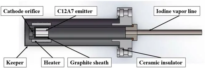
Figure 1.The configuration of the C12A7 hollow cathode with iodine propellant.
The configuration of the C12A7 hollow cathode designed for iodine propellant is illustrated in figure 1.The C12A7 hollow cathode tested on iodine has an orifice diameter of 3 mm of cathode tube and 3 mm of the keeper.The distance between the cathode tube and the keeper is 4 mm.The cathode orifice is relatively large compared with traditional hollow cathodes,which will be discussed in section 3.1.
The C12A7 electride emitter is a hollow cylinder with a length of 10 mm,an inner diameter of 3 mm,and an outer diameter of 5 mm.The electride emitter was developed and provided by the Beijing University of Technology,and has a measured work function of 1.9–2.4 eV.The C12A7 hollow cathode with an enlarged cathode orifice has been tested with Xe propellant,which has a nominal current of 1–4 A.
The experimental apparatus is illustrated in figure 2.The iodine reservoir was placed outside the vacuum for convenient operation on the power supply(PS)system.A He gas cylinder was connected to the iodine reservoir by a ball valve(valve 2)for gas replacement.The C12A7 hollow cathode was operated in aΦ 1.5 m×3 m vacuum chamber,which has a nominal vacuum pressure of 2.0×10⁻⁴Pa using two oil diffusion pumps.Despite some graphite collection plates and a customized cryotrap,the pumping speed was affected by iodine and its compounds in previous iodine experiments.The rapid decrease in the pumping speed of the diffusion pumps resulted in a vacuum of only 2×10⁻²Pa after dozens of hours of pumping and a vacuum of up to 1.5×10⁻¹Pa when the iodine flowed into the chamber.Such a vacuum high backpressure brings difficulty to the operation and stability of the hollow cathode[17].Ground experiments with iodine electric propulsion have always been a thorny issue,and so far there are no particularly effective protective measures to reduce the damage from iodine to the vacuum system.Some critical parameters,including the anode currentIa,anode voltageVa,keeper currentIk,and keeper voltageVk,are provided and measured by an IT6516 DC PS(750 V/15 A/1800 W)and an IT6515 DC PS(500 V/20 A/1800 W).The volt–ampere characteristics of the hollow cathode are recorded by a Tektronix MDO3054 mixed domain oscilloscope(500 MHz,2.5 GS/s).The temperature was measured by armored thermocouples and recorded by a temperature logger(GRAPHTEC midi LOGGER GL840).
2.2.Experimental procedure
As with conventional hollow cathodes,iodine hollow cathodes also require gas replacement to minimize impurities in the storage and supply system.As shown in figure 3,valve 1 and valve 2 will be kept on and off in proper order to inflate and deflate the feeding system with He gas,trying to eliminate the air and the gas impurities inside the feeding system.In the last time of gas replacement,the iodine tank was heated to 40 °C for 10 min.By opening valve 1,water and some other impurities will be eliminated from the iodine gas line.When the vacuum level returned to its minimum value again,about 2×10⁻²Pa,valve 1 was closed.Before the iodine hollow cathode experiment,a sufficiently stable iodine mass flow rate must be acquired.The iodine mass flow rate with a certain size was realized using a regulating heater PS and the flow restriction PS.The accurate temperature at corresponding parts is controlled by proportional-integral-derivative controllers(PID).The information about the iodine mass flow rate will be introduced later.The iodine vapors produced inside the reservoir run through a ball valve(valve 1)and flow into the hollow cathode after restriction by a heated throttle pipe.The iodine transfer pipes are wrapped by heating cables and a composite insulating layer to eliminate the congealing of iodine gas.The keeper PS was set at 350 V/0.5 A.The heating current was set at 3 A and increased gradually to warm the electride emitter until the C12A7 hollow cathode was ignited successfully.

Figure 2.The vacuum chamber and the experimental apparatus(the iodine tank is outside the chamber).
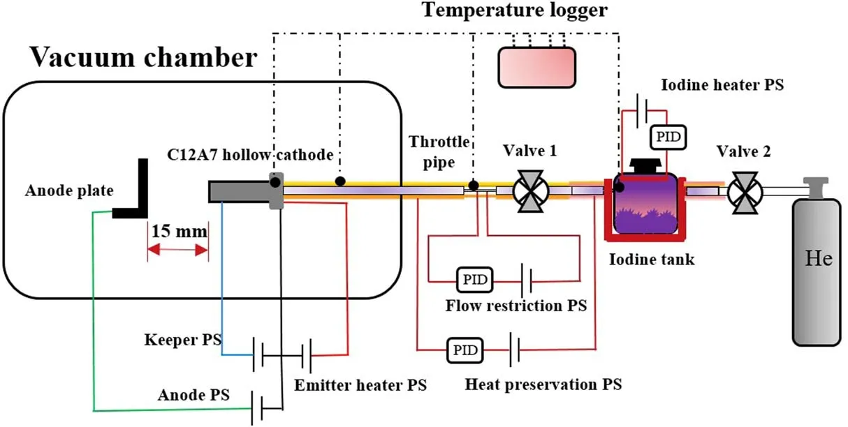
Figure 3.A schematic diagram of the iodine C12A7 hollow cathode experimental setup.
3.Results and discussion
3.1.Iodine flow investigation
Generally,a qualified iodine electric propulsion system requires an iodine feeding system with a certain flow rate,sufficient stability,and the lowest possible impurity gas.For real-time measurement and monitoring of the iodine flow rate,a method using the sublimation–condensation properties of iodine was proposed.As shown in figure 4,a specially designed aluminum collection bottle was located at a weight sensor with an accuracy of 0.1 mg.The collection bottle was carefully wrapped in a large cooling jacket.The iodine sublimated by the heat from the storage tank will be recondensed at the cold end of the collection bottle,leading to an increase in the mass of the collection bottle on the weight sensor.With real-time collected iodine mass,the evaluation of the real-time mass flow rate and the stability of iodine is available.
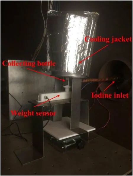
Figure 4.The experimental apparatus for the iodine mass flow rate measurement.
To obtain the target iodine mass flow rate of about 1 mg s−1that could support the ignition of the C12A7 hollow cathode,the temperature of the radiation heater inside the iodine reservoir was set at 250 °C.The temperature of the throttle pipe was set at 120 °C,and has an inner diameter of 1 mm and a length of 80 mm.The temperature of the gas lines wrapped with heating tapes was maintained at 100 °C.The mass of condensed iodine in the collection bottle and the iodine vapor pressure in the tank is shown in figure 5.It takes 30 min to raise the iodine vapor pressure in the tank to the saturation vapor pressure.During the iodine collection experiment,the vapor is stable at about 1600 Pa.The mass of collected iodine increased with time when valve 1 was opened at 100 s and grew to be stable after 400 s.The stable mass flow rate of iodine was calculated to be about 1–1.2 mg s−1.We quickly closed and reopened the valve at 900 s to confirm that the iodine flow was sustainable and stable.
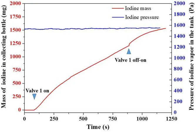
Figure 5.The real-time mass of collected iodine and the iodine vapor pressure inside the tank.
With regard to the experimental error,it is not possible to collect all the iodine in the cooling collection bottle.The real mass flow rate should be larger than that obtained from the iodine collection experiment.Therefore,a finite element method was also used to simulate the pressure distribution inside the system.The pressure inside the tank is set to saturation pressure,1600 Pa.The outlet is set to environment pressure,10 Pa.The wall temperature is set to 100 °C.The pressure distribution inside the supply system is shown in figure 6.The region with the largest pressure change gradient is in the throttle pipe.The pressure at the outlet of the supply line is approximately 870 Pa.The monitoring results of the iodine mass flow rate at the outlet show an iodine mass flow of approximately 1.4 mg s−1at a steady-state,which is slightly higher than the test results,as shown in figure 7.
Due to the lack of high-pressure cylinders and mass flow controllers,the flow of the iodine is strongly influenced by the upstream and downstream pressures.The upstream pressure is the saturation pressure of iodine vapor,which is no more than thousands of Pascal.The structure of the downstream cathode will have a large effect on the flow of iodine.Too small a cathode orifice is likely to lead to excessive pressure in the cathode tube,specifically to the‘gas holding effect’,resulting in a reduction of iodine flow.Therefore,it is necessary to investigate the flow of iodine in the hollow cathode.As shown in figure 8,the pressure inside the cathode tube is increased to 1340 Pa.The mass flow rate of iodine at the cathode exit decreased to about 0.9 mg s−1,seen in figure 9(a).In the hollow cathode with further decreased orifice diameter(1 mm),the iodine mass flow rate was reduced to 0.5 mg s−1.For iodine hollow cathodes where the iodine mass flow rate cannot be adjusted by the controller,enlarging the size of the cathode orifice is a way to ensure adequate iodine flow.
3.2.Performance of iodine hollow cathode
Before the iodine test,the C12A7 hollow cathode was operated in Xe with an ignition parameter of 300 V/1 A and 10 sccm Xe.With regard to the thermal sensitivity of the electride material,the extracted current should be no more than 4 A.In the iodine hollow cathode experiment,the keeper PS was set at 350 V/0.5 A,and the anode PS was set at 150 V/1 A.The ignition process of the iodine C12A7 hollow cathode can be divided into four phases:(1)glow discharge,(2)heating and reactivation,(3)arc discharge,and(4)self-sustained discharge.The typical voltage–current characteristics curve of the iodine C12A7 hollow cathode during ignition and operation are shown in figure 10.
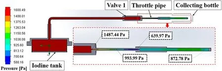
Figure 6.Pressure distribution of the iodine storage and supply system.
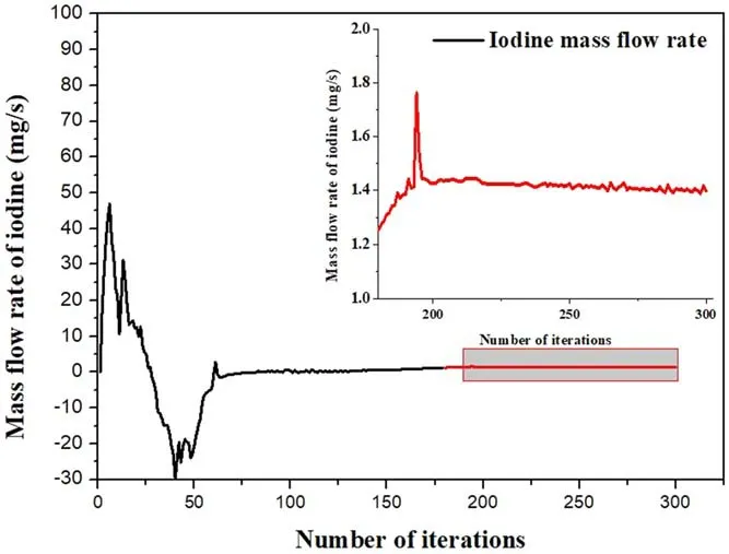
Figure 7.Monitoring of the iodine mass flow rate at the exit.
To prevent iodine condensation,the C12A7 hollow cathode was heated first with an external heater before iodine vapors entered.The keeper current of more than hundreds of milliampere was detected due to the thermionic emission of the electride emitter,as shown in figure 10.The glow discharge between the electride emitter and the keeper,with typical characteristics of high voltage and low current,indicated that the emitter had a promising thermionic emission capability.
The violent gas breakdown occurred at the moment of valve 1 opening because the high keeper voltage caused an iodine gas breakdown.The keeper voltage fluctuates between hundreds and tens of volts.Frequent shocks and sparks were also seen outside the keeper orifice due to the instability of the iodine and the impurities in it.The breakdown at high ignition voltage and the high mass flow rate was deliberate for not only heating the electride emitter to its emitting temperature but also in helping to eliminate a defect layer on the electride surface.It is believed that the electron deficient layer on the emitter surface may cause trouble to the thermionic emission of C12A7 electride.Without eliminating the electron deficient layer,relying solely on external heating to ignite the C12A7 hollow cathode is likely to fail[18,19].
The heating stage lasted about 100 s.The arc discharge formed instantly when the temperature of the emitter reached a certain level.The keeper voltage decreased from hundreds of volts to twenties of volts.The keeper current increased to the set value of 0.5 A and remained stable.To confirm that the current of 0.5 A is generated by the arc discharge,the keeper current was switched to 0.6 A.The PS of the keeper was switched from 0.5 A/16.24 V to 0.6 A/14.1 V instantly and remained stable for the duration.The anode PS was turned on and decreased from 150 V to 27.3 V/1 A.The heater was subsequently turned off and it was operated in the triode mode,as seen in figure 11.The C12A7 hollow cathode operated on iodine lasted for 7 min for the first time before the extinguishment.The radiation thermal shield,which is commonly used in LaB6and BaO-W hollow cathodes,was absent in the tested C12A7 hollow cathode,due to the potential melting risk for the electride emitter[20].It was suspected that the hollow cathode was stopped because the temperature of the emitter was too cold to sustain the discharge due to the absence of a thermal shield and heater power.The C12A7 hollow cathode could still be restarted with the same ignition parameters.It took about 85 s to shift to arc discharge mode.The heater power decreased from 3.5 A to 2 A instead of being completely turned off.The discharge lasted for 12 min and also winked out involuntarily.We retried several times and the hollow cathode could be started with the iodine propellant,but the duration varied from a few to ten minutes with occasional flicker and oscillation.Different keeper PS settings and iodine mass flow rates were tested in the next ignition cycles while being unable to extend the operation time.Detailed information about the operation parameters of the C12A7 hollow cathode is shown in table 1.In the last ignition cycle,the heater PS was suddenly switched from 3.5 A/22.1 V to 3.5 A/4.9 V,indicating a short circuit of the heater.

Figure 8.Pressure distribution of the iodine storage and supply system and the hollow cathode(orifice diameter is 3 mm).
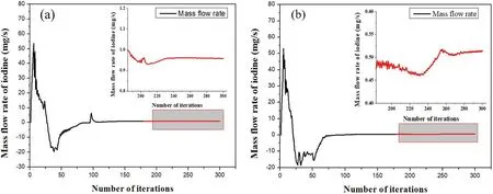
Figure 9.The iodine mass flow rate of the hollow cathode with different orifice diameters:(a)the cathode orifice is 3 mm,and(b)the cathode orifice is 1 mm.
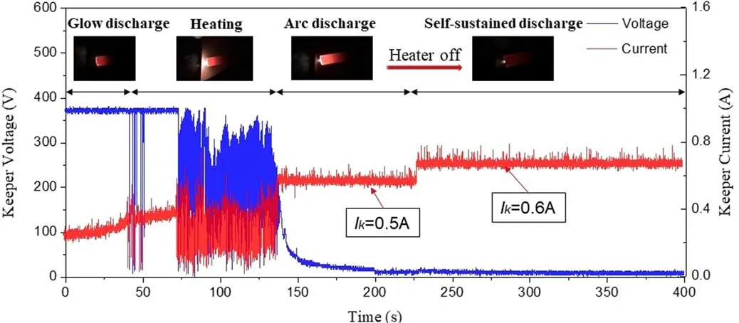
Figure 10.The volt–ampere characteristics curve of the iodine C12A7 hollow cathode.
We tried to use the heaterless ignition method to start the iodine hollow cathode when it was still warm.It is known that the heatless hollow cathode relies on the gas breakdown of propellant gas to warm the emitter.In the Xe C12A7 heaterless hollow cathode experiment,the gas breakdown occurred and continued with a keeper voltage(400 V)with a fixed constant flow rate(18 sccm).It usually takes tens of seconds for the Xe C12A7 hollow cathode to shift into arc discharge.In the heaterless C12A7 hollow cathode with iodine propellant,unusual phenomena were detected.The iodine gas breakdown occurred when the keeper voltage was set at 500 V.However,the gas breakdown is intermittent rather than continuous,as shown in figure 12.It usually stopped after seconds and happened again after a few seconds or minutes.Discontinuous iodine gas breakdown eventually leads to a glow discharge of the hollow cathode only,as shown in figure 13.The uncontrolled discharge indicated that the fluctuations in real iodine vapor flow may be so large as to exceed the breakdown voltage range allowed by Paschen’s law.
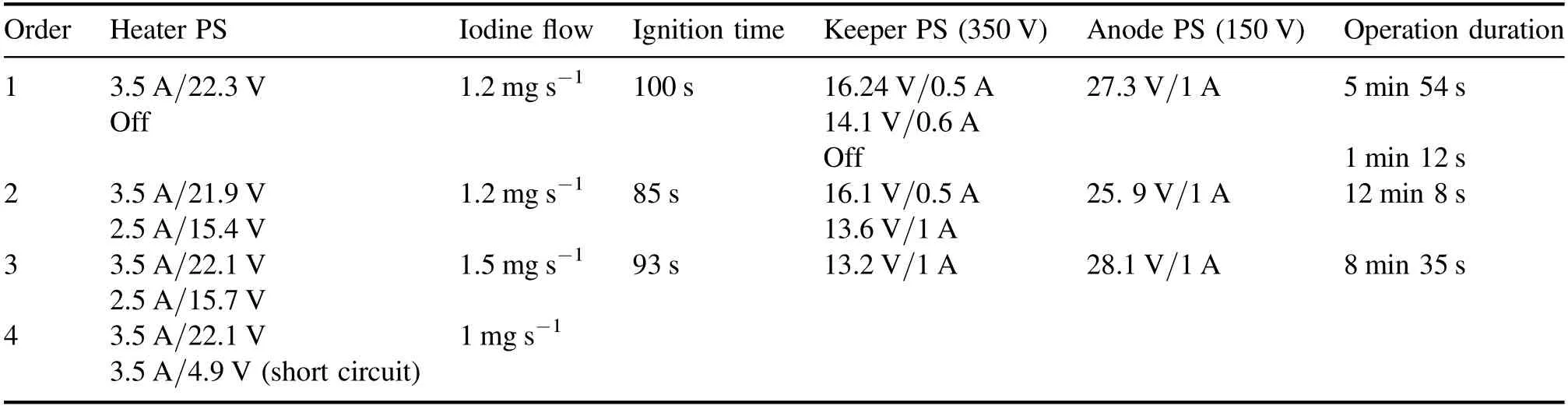
Table 1.Operation parameters of the C12A7 hollow cathode operated on iodine.

Figure 11.The C12A7 hollow cathode operated on iodine.(a)Operation in diode mode,Ik=0.6 A,Vk=14.1 V,and(b)operation in triode mode, Ia=1 A, Va=27.3 V.
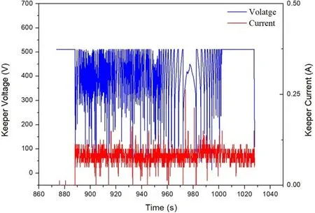
Figure 12.The volt–ampere characteristics curve of the heaterless C12A7 hollow cathode(discontinuous iodine gas breakdown).
With regard to the high-temperature gradient(200 °C–1200 °C in 80 mm)and plasma environment of the hollow cathode during the discharge,the real flow state of the iodine might be much more complicated than the simulation results or iodine collection experiments.The unexpected variation of pressure variation inside the hollow cathode might be responsible for the involuntary extinguishment of the arc discharge.
3.3.Discussions after iodine tests
Hollow cathode inspection after the iodine test is shown in figure 14.Within two hours of the end of the experiment,liquid and transparent iodine compounds were deposited on the anode plate,which turned to a brown color similar to iodine after the next day,as shown in figure 14(a).The electride emitter still has a black appearance,while spherical deposits of iodine compounds were detected on the cathode orifice plate,as shown in figure 14(b).Large numbers of solid iodine particles were scattered around the hollow cathode,indicating that the iodine propellant may not be used efficiently in the test,as shown in figure 14(c).The cathode tube was dissected to show that there was some iodine residue on the inner wall of the cathode tube and the emitter,as shown in figure 14(d).

Figure 13.Glow discharge of the heaterless C12A7 hollow cathode with iodine propellant.
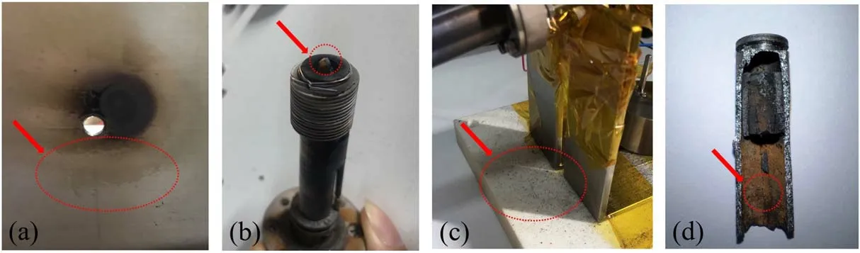
Figure 14.Inspection of the hollow cathode after the operation on iodine.(a)Liquid and transparent iodine compounds on the anode plate,(b)spherical iodine compounds deposited on the cathode orifice plate,(c)solid iodine particles spread around the cathode,and(d)iodine residue on the inner wall of the cathode tube and the emitter.
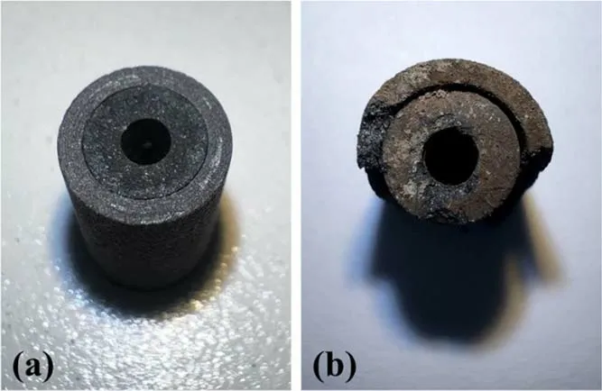
Figure 15.The electride emitter before(a)and after iodine discharge(b).
Before the failure of the external heater,the C12A7 hollow cathode had been operated for more than 30 min with three ignition cycles.No obvious degradation signs of the C12A7 hollow cathode,such as voltage increase and ignition difficulty,were detected during the iodine test.The electride emitter before and after iodine discharge is shown in figure 15.There is a yellow deposit on the end face of the emitter after iodine,but only a thin layer.The core layer is still the pure black crystal phase,which indicates that the C12A7 electride emitter is not oxidized or severely degraded(the C12A7 oxidation phase turns white after oxidation or decomposition).SEM(Scanning Electron Microscope)images show that the C12A7 layer remains intact and the iodine is only deposited on the surface without any corrosion layer,as shown in figure 16.Cracks and protrusions were observed on the surface of the emitter.Some spherical particles are dispersed on the internal surface.This indicates the decomposition of the electride emitter due to overheating,which most likely occurred at the heaterless ignition phase.However,small amounts of elemental iodine(I)and molybdenum(Mo)were detected in the EDS(Energy Dispersive Spectroscopy)results,as shown in figure 17.The element ratios of Ca to Al at the tested regions are 25.15%:26.95%,roughly equivalent to 6:7,indicating that the Ca/Al mole ratio nearly matched the standard stoichiometric ratio in the C12A7 electride(12CaO·7Al2O3:4e−).The degree of decomposition and the composition of decomposition products need to be further investigated to discuss the effects on the hollow cathode performance.
4.Conclusions
This paper introduced the initial experimental investigation of a low-current C12A7 hollow cathode operated with iodine propellant.The purpose of this study is to verify the performance of the developed iodine storage and supply system,as well as the feasibility of the C12A7 hollow cathode with iodine propellant,trying to achieve a technological breakthrough for the single-iodine Hall electrical propulsion system.
First,the iodine storage and supply system that enables real-time observation of iodine mass was developed.An iodine mass flow rate of 1–1.2 mg s−1was acquired for the iodine hollow cathode.With the experiment data,a finite method was used to simulate the iodine flow inside the iodine line and the hollow cathode.The results show that the downstream structure of the hollow cathode has a significant effect on the iodine mass flow,especially the cathode orifice.Hence,the orifice of the hollow cathode was enlarged to 3 mm to ensure an adequate iodine mass flow rate.
Before the iodine experiment,the C12A7 hollow cathode with a nominal current of 1–4 A was tested with Xe propellant.In iodine tests,the C12A7 hollow cathode is ignited by an external heater with a keeper voltage of 350 V and a keeper current of 0.5 A.It works stably at 1 A of anode current with a single operating time of more than 10 min and a total duration of 30 min.Despite involuntary extinguishment,the cathode can be started repeatedly.In the heaterless iodine C12A7 hollow cathode experiments,discontinuous iodine gas breakdown at fixed high voltage indicated large pressure variations at the cathode orifice.Unexpected iodine flow fluctuation during hollow cathode operation might be the reason for the interrupted discharge.
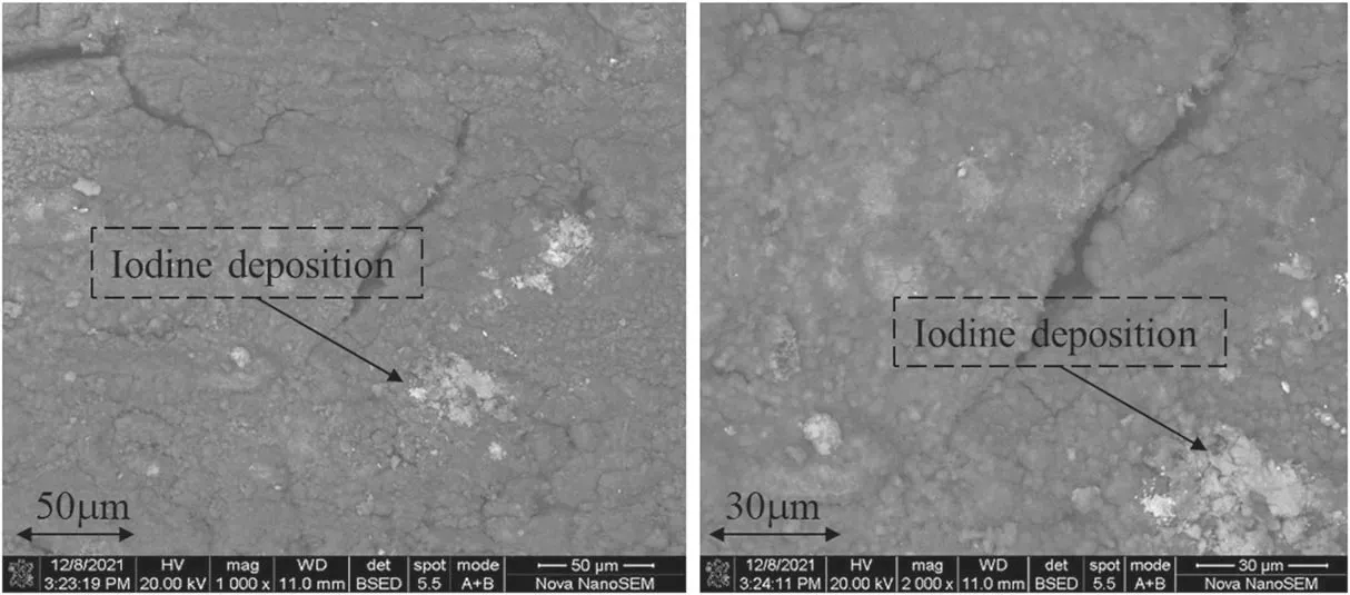
Figure 16.SEM images of the electride emitter after iodine discharge.
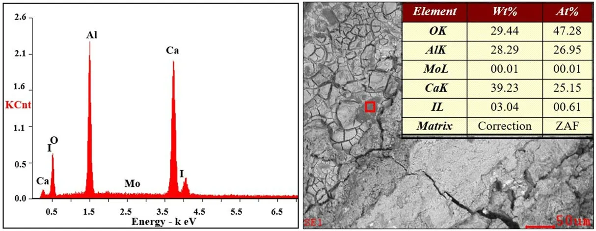
Figure 17.EDS results of the electride emitter after iodine discharge.
Post experimental examination of the hollow cathode revealed a small amount of iodine residue in the cathode tube.No obvious oxidation or erosion was detected after iodine discharge according to the SEM and EDS analysis of the electride emitter.
Future work includes improvements to the iodine storage and supply system for more accurate and stable iodine flow control.The iodine hollow cathode also needs to be further optimized to be better adapted to the iodine flow state for a longer duration of the iodine hollow cathode and the demonstration of iodine Hall electrical propulsion.
Acknowledgments
This work is supported by the Joint Fund for Equipment Preresearch and Aerospace Science and Technology(No.6141B061203).
ORCID iDs
猜你喜欢
杂志排行

Plasma Science and Technology的其它文章
- Characteristics of plasma in a novel laserassisted pulsed plasma thruster
- The effect of anode axial position on the performance of a miniaturized cylindrical Hall thruster with a cusp-type magnetic field
- Investigation into the thermal effect of the LIPS-200 ion thruster plume
- Numerical study of the effect of aft-loaded magnetic field on multiple ionizations in Hall thruster
- Simulation of a helicon plasma source in a magnetoplasma rocket engine
- Numerical simulation of the start-up process of a miniature ion thruster