The effect of anode axial position on the performance of a miniaturized cylindrical Hall thruster with a cusp-type magnetic field
2022-08-01YuanyuanGAO高园园WeizongWANG王伟宗YifeiLI李亦非ShuwenXUE薛舒文andGuobiaoCAI蔡国飙
Yuanyuan GAO(高园园),Weizong WANG(王伟宗),2,∗,Yifei LI(李亦非),Shuwen XUE(薛舒文) and Guobiao CAI(蔡国飙)
1 Advanced Space Propulsion and Energy Laboratory(ASPEL),School of Astronautics,Beihang University,Beijing 100191,People’s Republic of China
2 Aircraft and Propulsion Laboratory,Ningbo Institute of Technology,Beihang University,Ningbo 315832,People’s Republic of China
Abstract A 200 W cylindrical Hall thruster with a cusp-type magnetic field was proposed,manifesting convergent plume and high specific impulse.In this paper,a series of ring-shaped anodes are designed and the influence of anode axial position on the performance of CHT with a cusp-type magnetic field is studied.The experimental results indicate that the thruster keeps stable operation at the condition of 140–270 W discharge power.When the anode moves axially towards the upstream cusp field,the thrust enhances from 6.5 mN to 7.6 mN and specific impulse enhances from 1658 s to 1939 s significantly.These improvements of thruster performance should be attributed to the enhancement of current utilization,propellant utilization and acceleration efficiency.According to the analyses on the discharge characteristics,it is revealed that as the anode moves upstream,the electron transport path could be extended,the magnetic field in this extended path could impede electron cross-field transport and facilitate the ionization intensity,yielding to the enhancement of current utilization and propellant utilization efficiency.Moreover,along with this enhancement of upstream ionization at the given anode flow rate,the main ionization region is thought to move upstream and then separate more apparently from the acceleration region,which has been demonstrated by the narrowing of ion energy distribution function shape.This change in acceleration region could decrease the ion energy loss and enhance acceleration efficiency.This work is beneficial for optimizing the electrode structure of thruster and recognize the ionization and acceleration process under the cusp magnetic field.
Keywords:performance,ionization characteristics,acceleration characteristics,cylindrical Hall thruster,anode axial position
1.Introduction
Micro-nano satellites demands a new generation of miniaturized propulsion system with more accurate thrust and more precisely positioning[1,2].As a type of electromagnetic plasma propulsion device,Hall thruster has achieved mature application in medium-power and high-power field due to its high performance and high reliability[3,4].Therefore,low-power miniaturized hall thrusters attract lots of research interests,among which cylindrical Hall thrusters(CHT)could achieve stable operation in the power range of 50–300 W by shortening the internal magnetic poles and presenting cylindrical discharge channels[5,6].Plasmas in a CHT is constrained by a strong magnetic mirror field,in which the maximum magnetic field magnitude exceeds 1000 G[7].The performance characteristics of CHTs are high ionization rate and low wall erosion rate[8].In previous research,a CHT with upstream cusp magnetic field was proposed,which manifests collimated plumes and high specific impulse[9].This CHT with upstream cusp magnetic field opens a new perspective for developing high-efficiency miniaturized thrusters.
Generally,the electrode configuration could play a crucial role in discharge process by controlling electron transport and electric field structure[10–14].In Hall thruster,lots of literatures investigated the effect of electrode configuration on the thruster ionization and acceleration.In order to reduce the aggravating coupling of ionization and acceleration process at high-voltage operation condition,Zhanget alproposed a design of additional electrode at the strongest magnetic field inner the channel.They found experimentally that these two positive electrodes configuration could achieve the clearer separation of ionization stage and acceleration stage effectively and produce a more collimated plume[12].Meanwhile,Mazouffreet almoved the anode axially from the channel upstream to exhaust in the magnetic shielding Hall thruster.The experiment results indicated that under the magnetic field with magnetic lines approximately parallel to the ceramic wall,this change of anode position could rise the potential at the wall adjacent to thruster exhaust and impede the bombardment of ceramic wall by ions effectively[13].In addition,Harbin Institute of Technology investigated the effect of radial anode position for the performance of CHTs with traditional direct magnetic field.It has been found that due to the strong magnetic field distributed near the channel upstream,the radial movement of anode towards outer wall could increase the confinement of electrons and enhance the ionization efficiency[14].Consequently,the optimal electrode configuration of the thruster should match its magnetic field.
Naturally,it raises a question that how the anode designs under this new type of upstream cusp magnetic field of CHT.In view of this question,a series of ring-shaped anodes with different axial position are designed in this paper to investigate the effect of anode axial position on the performance of CHT with upstream cusp magnetic field.This paper is organized as follows.The relevant designs of the CHT with the upstream cusp magnetic field are introduced and the experimental setup is described in section 2.In section 3,the measured results of the performance characteristics,electron transport and ionization characteristics,ion beam acceleration characteristics with the different anode axial position are presented and then the physical process and the discharge features under the upstream cusp magnetic field are discussed as well.Finally,conclusions are summarized in section 4.
2.Experimental setup
The structure of CHT in our experiment is shown in figure 1.The CHT is comprised of inner and outer ceramic walls,a ring-shaped anode,a gas distributor,electromagnetic coils,etc.In our experiment,the ring-shaped anode was separated from the gas distributor to investigate the effect of axial position for discharge characteristics independently and exclude the effect of gas distributor position for the ionization distribution.A series of ring anodes with different axial coordinates was mounted near the outer wall,as shown in figure 2.The axial coordinate value corresponding to upper surface position of the anode is defined asZa=0 mm when the anode is flush with the inner wall surface.As the anode moves upstream,the axial coordinate value corresponding to upper surface positions of the anode areZa=0 mm,−3 mm,−6 mm,and −9 mm.In addition,the anode position could be indicated as the axial distance between anode and inner wall|Za| as well.The distance between the upper and the lower surface of the anode is constantly 1.5 mm.The surface area of the ring anode is 141.3 mm2.
The upstream cusp magnetic field is formed as the current in the middle coil is counter-directed to that in other two coils,as shown in figure 2.In this magnetic field configuration,a zero magnetic ring appears near the gas distributor.The strongest magnetic field is located near the inner wall close to the axis,its magnetic flux density is up to 1200 G.The axial distribution of magnetic field magnitude in the channel are shown in figure 3.
The experiments were operated in a vacuum chamber with 4.5 m in length and 1.5 m in diameter.The background pressure was maintained below 2×10⁻³Pa in the operation.Xe was chosen as the propellant gas.The discharge voltageUdwas varied in the range of 200–400 V,and the anode flow ratem˙awas 0.4 mg s−1.A hollow cathode was used to emit the electrons,its orifice is located at an axial distance of 3.5 cm from the exit plane and a radial distance of 3.5 cm from the thruster axis of symmetry.The cathode Xe flow rate was fixed at 0.2 mg s−1,and the keeper current was 1 A.
The vacuum testing system schematics are shown in figure 4.A three-thread torsion balance was used to measure the thrust.The torsion balance can transform the thruster force to an equivalent rotation angle,which was recorded by the displacement of laser spot on a steel ruler[15].Then the thrust can be calculated from the equivalent displacement generated by the weights.The plasma plume characteristics were diagnosed by a Faraday probe and a retarding potential analyzer(RPA).The Faraday probe was employed to measure the ion current density in different angular directions,then ion currentIiwas calculated by integrating the angular ion current density from −90° to+ 90°[15].RPA was used to measure the ion current density angular distribution with the varying ion retarding potential and the ion energy distribution function(IEDF)[16,17].The Faraday probe and RPA were both mounted on a rotational stage at an axial distance of 30 cm from the pivot and an azimuthal angle of up to 90° from the thruster axis of symmetry.In addition,a digital single-lens refelx camera was mounted on a side window of the vacuum chamber to capture the thruster discharge images.
3.Experimental results and discussions
3.1.Thruster performance characteristics
Figure 5 depicts the volt–ampere characteristics with the varyingZa.It is found that when the anode flow rate is fixed at 0.4 mg s−1and the discharge voltageUdrises from 200 V to 400 V,the CHT maintains the stable operation with the discharge power ranging from 140 W to 270 W.Meanwhile,withZachanging from 0 mm to −9 mm,the discharge current becomes smaller at the fixedUd.Moreover,it is noted that for the low anode axial coordinate valueZa=0 mm,the discharge current rises along with theUdand the upper threshold ofUdkeeping stable operation is 320 V.In contrast,for the large anode axial coordinate valueZa=−9 mm,the discharge current declines apparently withUdand the upper threshold ofUdreaches 400 V.Not that the stable working voltage here indicates the upper threshold value of discharge voltage maintaining the current stability and thermal stability of thruster operation.Once the given discharge voltage exceeds this upper threshold value,the thruster is likely subjected to the abrupt increasing of discharge current and the overheating of anode,both the current stability and thermal stability would be hardly maintained,moreover,the dramatic current oscillation would also be likely to happen.Therefore,it is concluded that the discharge voltage range extends apparently and the operation stability of thruster enhances with the upstream movement of anode.
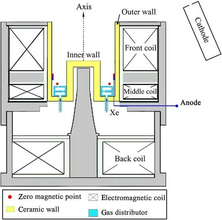
Figure 1.Schematic of CHT in the experiment.
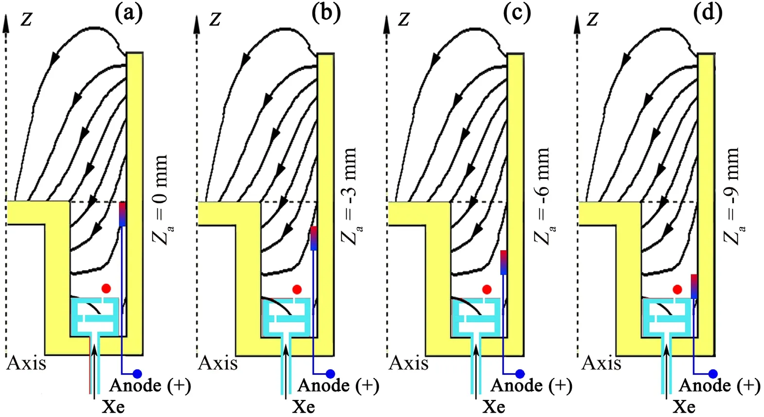
Figure 2.CHT configurations with different anode axial positions Za:(a)Za=0 mm,(b)Za=−3 mm,(c)Za=−6 mm,(d)Za=−9 mm.
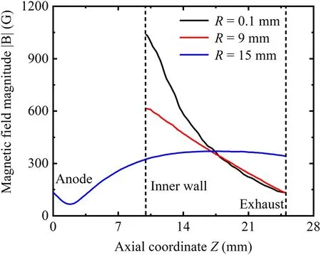
Figure 3.Magnetic field magnitude distribution in the discharge channel.The currents in the front,middle,and back coils were+3 A/−4 A/+3 A.
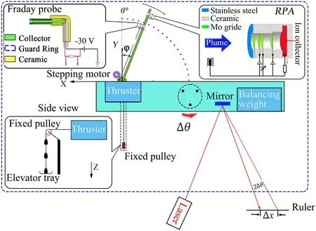
Figure 4.Vacuum testing system including the thrust stand and plasma probes.
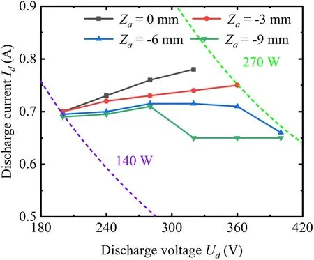
Figure 5.Volt–ampere characteristics with the varying anode axial position.
Figure 6 depicts the testing results of thrustT,specific impulseIspand anode efficiencyaηagainst the anode axial positionZa.The specific impulse and anode efficiency could be calculated by the following equations.wherem˙adenotes the anode flow rate,Padenotes the discharge power.It is found that when the anode ends flush with the inner wall(|Za|=0 mm),the thruster produces 6.5 mN thrust with the consuming discharge power of 246.4 W.In contrast,as |Za| increases from 0 mm to 9 mm,the thruster produces 7.6 mN thrust with the consuming power of 211.3 W.Apparently,the thrustTis elevated by 16.9%.Correspondingly,Ispenhances from 1658 s to 1939 s,aηenhances from 21.8% to 34.1%.This enhancement of comprehensive thruster performance should be related intimately with the discharge characteristics involving electron transport,ionization and acceleration,which could be studied as follows.
3.2.Electron transport and ionization characteristics
Figure 7(a)depicts the test results of ion currentIiand propellant utilization efficiencyη.pSpecifically,the propellant utilization efficiencyηpis a measure of how many propellant atoms are ionized[18],which could be described as follows:
whereM,eandm˙adenote the mass of the Xe atom,the electron charge,and the anode mass flow rate,respectively.As|Za|increases from 0 mm to 9 mm,Iiandηpboth increases by 7.8%,it is concluded that the ionization efficiency should enhance with the upstream shift of anode.In addition,note that the propellant utilization efficiency in this paper is larger than unity,which could be mainly attributed to the presence of multi-charged ions in CHT.Kimet aland Smirnov have demonstrated experimentally and numerically that the presence of multi-charged xenon ions in ion flux could be the dominant cause of propellant utilization efficiency exceeding unity(ηp> 1)in cylindrical Hall thruster[19,20].
In fact,Boeuf previously suggested that the ionization characteristics are related intimately with the confinement level of magnetized electrons,which is evaluated by the electron transport currentIeand the current utilization efficiencycη[3].In experiment,Ieis calculated by subtracting the ion currentIifrom the discharge currentId.cηis obtained by calculating the proportion ofIiin theId[21].Figure 7(b)depicts the test result ofIeandcηwith the varyingZa.It is found that as|Za|increases from 0 mm to 9 mm,Iedecreases by 19%,correspondingly,cηenhances by 15.2% apparently(from 0.59 to 0.68).
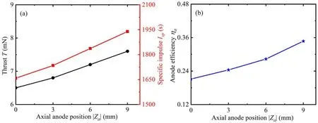
Figure 6.(a)Thrust and anode efficiency,(b)specific impulse with the varying anode axial position.The discharge voltage and anode flow rate are fixed at 320 V,0.4 mg s−1.
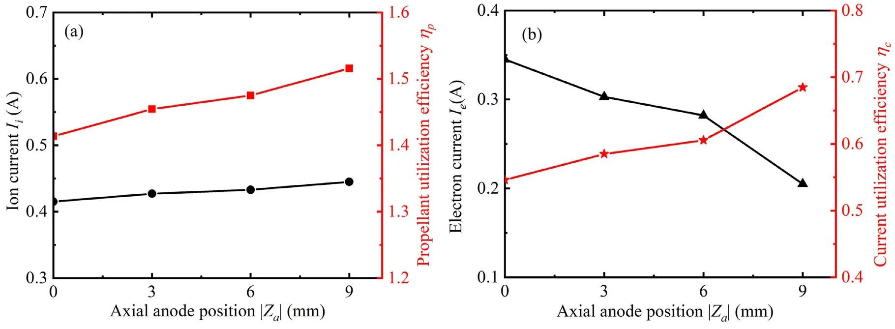
Figure 7.(a)Ion current and propellant utilization efficiency,(b)electron current and current utilization efficiency with the varying anode axial position.The discharge voltage and anode flow rate are fixed at 320 V,0.4 mg s−1.

Figure 8.(a)Ion current proportionσ and(b)half-plume angle θ,with the varying RPA ion retarding voltage Up.The discharge voltage and anode flow rate are fixed at 320 V,0.4 mg s−1.Note that the ion current ratioσ indicates the proportion of ion current with the energy
It is suggested that the electron transport path should be extended along with the upstream shift of anode.Combing the magnetic field magnitude distribution in figure 3,it is noteworthy that the positive-gradient magnetic field distributes in this extending region,which has been demonstrated previously to facilitate the formation of stable azimuthal Hall drift and impede the electron cross-field transport efficiently[22,23].Moreover,the propellant atoms from upstream gas distributor could prefer to collide and ionization with these electrons,which yields to the enhancement of ionization efficiency.
3.3.Ion beam acceleration characteristics
In order to study the ion beam acceleration characteristics,RPA was employed to sweep the plasma plume at ± 90° and ion current with the energyeion>eUpare obtained by integrating the angular ion current density from - 90° to + 90°collected by RPA with a specific ion retarding voltageUp.Note that total ion current measured by the RPA atUp=0 V approximately coincides with the ion currentIimeasured by the Faraday probe.Furthermore,the ion current ratioσis obtained by calculating the proportion of ion current with the energyeion>eUpin total ion current.Correspondingly,the correlation between ion current proportion/plume angle and retarding voltage could be calculated.As shown in figure 8(a),compared with that forZa=0 mm case,the ion current proportionσbecomes higher with the increasing retarding voltage forZa=−9 mm case,which means that the high-energy ion current proportion increases with the upstream shift of anode.Moreover,the plume angle corresponding to this high-energy ion beam reduces significantly,as shown in figure 8(b).In addition,note that the plume angle atUp=0 V forZa=−9 mm case is 50 deg,lower apparently than 56 deg forZa=0 mm case.
In addition,the IEDFs for different angular direction are measured for anode axial coordinateZa=0 mm andZa=−9 mm,respectively.It is found that forZa=0 mm case,the most probable ions energies of IEDF caves decrease slightly by 2.2% with the angle varying from 0 deg to 30 deg(as shown in figure 9(a)).In contrast,forZa=−9 mm case,the most probable ions energies of IEDF caves decrease apparently by 15.4% with the similar angle varying from 0 deg to 30 deg(as shown in figure 9(b)).Meanwhile,combining with figures 9(a)and(b),it is found that the width of IEDF shape becomes narrowing significantly with the upstream shift of anode axial position:the full width at half maximum(FWHM)of ion energy at axis(0 deg)forZa=−9 mm case is 65 eV,lower apparently than 97 eV forZa=0 mm case.Consequently,the acceleration characteristics of ion beam indicates the collimating of high-energy ion beam towards axis and the narrowing of ion energy distribution along with the upstream moving of anode,which could induce the ions undergoing a larger effective potential drop and facilitate the enhancement of acceleration efficiency.
3.4.Discussion on the physical process
The above ionization and acceleration characteristics reveal that their intrinsic physics process could change significantly with the moving of anode axial position towards the upstream cusp field.Specifically,as the anode ends flush with the inner wall(Za=0 mm case),the cusp field is non-effective for the electron confinement in discharge chamber and its effective magnetic field for trapping electrons is the near-axis magnetic mirror field,similarity to the traditional diverging magnetic field of CHT.Previous literatures have demonstrated that under this magnetic field,the main ionization should extend along the axis and the ionization region and acceleration region should be overlapped strongly due to the electrons bouncing back and forth along the axial direction[7,8].
While as the anode moves towards upstream cusp field axially(Za=−9 mm case),the electron transport path could be extended and the cusp field could work gradually for confining electrons,which could impede the electron crossfield transport efficiently and prolong the electron residence time,facilitating the local ionization.At a given anode propellant flow rate,this intensification of upstream ionization could decrease significantly the neutral atom density flowing to the downstream channel center and then reduce the ionization there.Furthermore,it is suggested that the main ionization region should move towards upstream along with the anode,which could be likely to facilitate the clearer separation of the acceleration region from the ionization region.Moreover,this separation is confirmed by the significant narrowing of IEDF shape as stated above.Wellknown,the width of IEDF shape in plume is determined by the relative distance of ionization and acceleration regions to a large extent and the narrower IEDF means the larger relative distance of ionization and acceleration region[24].Therefore,it is concluded that as the anode moves axially towards the upstream cusp field,the ionization could be intensified due to the reduction of local electron cross-field transport,meanwhile,the relative position between ionization and acceleration regions should become larger and the ions could undergo a larger effective potential drop.These factors could lead to the enhancement of thrust and specific impulse.
3.5.Discussions on the discharge features under the upstream cusp magnetic fielde ion > eUp in total ion current.
Figure 10 and table 1 indicate the comparisons between the upstream cusp magnetic field and the traditional direct magnetic field reported by A Smirnovet al[20],including the discharge voltage range maintaining the current and thermal stability,plume characteristics,electric transport characteristics,specific impulse and so on.As shown in figure 10,a ring of zero magnetic field(red dot in figure 10)is located at the upstream region under the upstream cusp magnetic field,in contrast,dense magnetic lines are distributed at the upstream region under the conventional direct magnetic field.

Figure 9.Ion energy distribution for(a) Za=0 mm,and(b) Za=−9 mm.
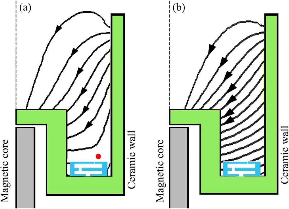
Figure 10.Comparisons of the upstream cusp magnetic field and conventional direct magnetic field.(a)The upstream cusp magnetic field for Za=−9 mm case;(b)the traditional direct magnetic field proposed by A Smirnov et al[20].
As shown in table 1,comparisons of discharge feature for these two magnetic field configurations indicate that:(1)under the upstream cusp magnetic field in this paper,the upper threshold of discharge voltage maintaining the stable operation reaches up to 420 V(as shown in figure 5),while this upper threshold of discharge voltage under the traditional direct magnetic field is 300 V[20].(2)CHT with the upstream cusp magnetic field could produce a more collimated plume.Its plume angle is 50 deg(as shown in figure 8),apparently lower than 55 deg under the conventional direct magnetic field.(3)At the same anode flow rate of 0.4 mg s−1and discharge voltage of 300 V,the electron currentIeunder the upstream cusp magnetic field is 0.2 A,apparently lower than 0.37 A under the traditional direct magnetic field.Moreover,its current utilization efficiencycηreaches up to 0.68,much larger than 0.5 under the traditional direct magnetic field.This electron transport characteristic indicate that the upstream cusp magnetic field could impede the electron cross-field transport efficiently.(4)The highest specific impulse and the largest thrust-to-power ratio under the upstream cusp magnetic field are 1939 s and 35.5 mN kW−1,respectively.In contrast,the corresponding values under the traditional magnetic field reported by A Smirnovet alare 1530 s and 28.5 mN kW−1.
Furthermore,these physical phenomena(involving the high upper threshold of discharge voltage,the large current utilization efficiency and the convergent plume at the condition of the high discharge voltage,i.e.)under the upstream near-anode cusp magnetic field could be explained as follows:
(1)Well-known,the upper threshold of discharge voltage and the current utilization efficiency are associated with the electron mobility level under the action of the magnetic field.In this paper,the upstream cusp magnetic field manifests the distribution characteristics of positive magnetic field gradient in the annular region.This type of distribution has been demonstrated to reduce the plasma instability and impede the electron transport efficiently in theory[22,23].This effect on increasing of electron resistance is also confirmed by the above experimental results.At a high discharge voltage of 300 V,the electron transport current is significantly lower under the cusp magnetic field than under the traditional magnetic field.Therefore,under the cusp magnetic field,the heat stress on the anode surface is alleviated remarkably.Consequently,the upper threshold of stable working voltage is lifted.Meanwhile,the electron residence time in channel could be prolonged and then more ions will be ionized at the lower electron current,which leads to the enhancement of current utilization efficiency.
(2)The overlapping area between the ionization region and accelerate region is smaller under the cusp magnetic field(which has been confirmed by the narrowing of its IEDF shape in[9]).This phenomenon could enhance the effective accelerating voltage undergone by the ionsgenerated in the ionization region and then reduce the ions residence time in the channel,correspondingly reduce collisions probability of ions with other particles and lead to the plume narrowing.
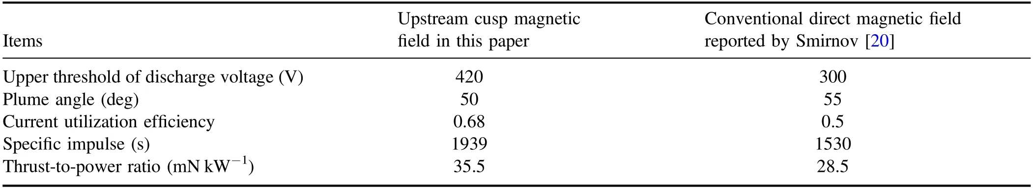
Table 1.Comparisons of discharge feature for two magnetic field configurations.
4.Conclusions
This paper investigates the effect of anode axial position on the performance of CHT with upstream cusp magnetic field.A series of ring-shaped anodes are designed with different axial position.The experimental results indicate that as the anode ends flush with the inner wall(Za=0 mm case),the cusp field is non-effective for the electron confinement in discharge chamber and its effective magnetic field for trapping electrons is the nearaxis magnetic mirror field.This collocation could produce the low current utilization efficiency(cη=0.55)and diverging plume(the plume angle as large as 56 deg)due to the strong coupling between ionization and acceleration process.While as the anode moves axially towards the upstream cusp field,the electron transport path could be extended,the cusp magnetic field in this extended path could impede electron cross-field transport efficiently,yielding to a significant enhancement of current utilization efficiency(by 15.2%).Meanwhile,the ionization process in this extending region could be facilitated due to the increasing of electron residence time,leading to the increasing of propellant utilization efficiency(by 7.8%).Moreover,along with this enhancement of upstream ionization at the given anode flow rate,the main ionization region is thought to move upstream and then separate more apparently from the acceleration region,which has been demonstrated by the narrowing of IEDF shape.This change in the ionization and acceleration region could improve the rising of acceleration efficiency and the converging of plume(the plume angle is decreased to 50 deg).As a result,the significant enhancement of thrust(by 16.9%)and specific impulse(by 16.9%)are achieved.
Acknowledgments
The authors acknowledge support from the Defense Industrial Technology Development Program(No.JCKY2019601D112).
杂志排行

Plasma Science and Technology的其它文章
- Characteristics of plasma in a novel laserassisted pulsed plasma thruster
- Investigation into the thermal effect of the LIPS-200 ion thruster plume
- Early experimental investigation of the C12A7 hollow cathode fed on iodine
- Numerical study of the effect of aft-loaded magnetic field on multiple ionizations in Hall thruster
- Simulation of a helicon plasma source in a magnetoplasma rocket engine
- Numerical simulation of the start-up process of a miniature ion thruster