Design and evaluation of cab seat suspension system based on negative stiffness structure
2021-07-13LiaoXinZhangNingXingHaijunZhangWanjie
Liao Xin Zhang Ning Xing Haijun Zhang Wanjie
(1School of Mechanical Engineering, Shijiazhuang Tiedao University, Shijiazhuang 050043, China)(2State Key Laboratory of Mechanical Behavior and System Safety of Traffic Engineering Structures, Shijiazhuang Tiedao University, Shijiazhuang 050043, China)(3School of Mechanical Engineering, Southeast University, Nanjing 211189, China)
Abstract:To improve the vibration-isolation performance of cab seats, the optimization model of the seat suspension system of construction machinery cabs is proposed based on the negative stiffness structure. The negative stiffness nonlinear kinetic equation is established by designing the seat negative stiffness suspension structure (NSS). Using MATLAB, the different parameters of the suspension system and their influences on the dynamic stiffness are analyzed. The ideal configuration parameter range of the suspension system is obtained. Meanwhile, the optimization model of NSS is proposed, and the vibration transmissibility characteristics are simulated and analyzed by different methods. The results show that the displacement and acceleration amplitudes of the optimized seat suspension system are evidently reduced, and the four-time power vibration dose value and root mean square calculation values in the vertical vibration direction of the seat decrease by 86% and 87%, respectively. Seat effective amplitude transmissibility (SEAT) and the vibration transmissibility ratio values also decrease. Moreover, the peak frequencies of the vibration transmitted to the driver deviate from the key frequency values, which easily cause human discomfort. Thus, the design of the seat suspension system has no effect on the health condition of the driver after being vibrated. The findings also illustrate that the NSS suspension system has good vibration-isolation performance, and the driver’s ride comfort is improved.
Key words:construction machinery; negative stiffness structure; seat suspension system; dynamic properties; ride comfort
In recent years, with the continuous improvement of road traffic, more attention has been paid to the ride comfort and humanized design of vehicle seats. In construction machinery vehicles, cab seats are vibrated to various degrees during the vehicle operation[1]. Traditional studies mainly focus on the vibration isolation of engines and vehicle-mounted equipment of construction machinery[2-4]. However, long periods of forced vibration in the working environment will cause driver fatigue and lead to frequent accidents. The driver’s mental and physical health will also be seriously damaged. Cervical, spinal, and pelvis injuries of the human body frequently occur[5-6]. Thus, the research and development design of seat suspension systems are closely related to people’s life. Advocating people-orientedness, fully considering the driver’s physical feelings and strengthening their protection, and improving the working environment are important development directions of vehicle seat suspension systems.
The vibration-isolation mechanism of parallel springs with a negative stiffness structure is a new type of nonlinear vibration-isolation device, and it can significantly improve the vibration-isolation effect, especially the low-frequency ones. van Eijk et al.[7]first used negative stiffness in the mechanical design of leaf springs to reduce the total stiffness of the system. Lee et al.[8]developed the seat vibration-isolation mechanism with the negative stiffness based on the thin-shell theory and offered theoretical derivation and experimental verification, which achieved good results. Yang et al.[9]studied the dynamics and power flow behavior of a nonlinear vibration-isolation system with a negative stiffness mechanism and derived the nonlinear dynamic equations of the system; they obtained the frequency response function of the system under harmonic excitation by using the average method. Han et al.[10]used a kind of bending mounted spring-roller mechanism as a negative stiffness calibrator in parallel with a vertical linear spring and developed and designed a passive nonlinear isolator; they also analyzed the dynamic characteristics of the isolator. Fan et al.[11]developed a vibration absorber of positive and negative stiffness elastic elements in parallel by the principle of counteraction of the elements. Its stiffness can be arbitrarily low. Zhang et al.[12]studied a new type of vibration-isolation system with positive and negative stiffnesses in parallel. This system had a high support stiffness and a low motion stiffness. The natural frequency can be reduced by adjusting the magnitude of force at both ends of the negative stiffness mechanism. The vibration-isolation effect was improved significantly. Ji et al.[13]proposed a new type of vibration-isolation system with a negative stiffness damping device (NSD) attached to the ordinary vibration isolation layer and discussed the effect of NSD on the performance of the vibration isolation system. In recent years, numerous scholars have carried out a series of studies on the negative stiffness structure[14-20]. However, little literature focused on the in-depth research of negative stiffness structure for cab seats of construction machinery vehicles. Therefore, it is necessary to establish an accurate seat suspension system with the characteristics of a negative stiffness suspension structure (NSS) and analyze its dynamic features; the ideal parameters of the system need to be designed based on the space size of the cab seat.
In this paper, the nonlinear dynamic model of the cab seat suspension system based on the negative stiffness structure is first established, and the Runge-Kutta method is used to discuss the different structural parameters and their influence on dynamic stiffness to determine the ideal configuration parameter range of the suspension system. Based on the initial results, the optimization model of the seat suspension structure of construction machinery cabs is put forward, and a nonlinear simulation analysis is carried out to study the vibration transfer characteristics of this suspension system. In accordance with the ISO 2631 standard, different methods are used to evaluate the ride comfort of the seat to improve the working environment of drivers and reduce vibration.
1 Model Description
The vehicle cab seat model consists of three parts:the seat suspension system, seat structure frame, and driver (see Fig.1). In the analysis of the dynamic characteristics of seat suspension specifically, the weights of the seat and the human body are simplified into a rigid mass blockM, and the elasticity of the cushion, the damping inside the human body, and the weight of the connecting rod and joint are neglected. The simplified model contains two symmetrical negative stiffness structures, dampers, a mass block, and a supporting spring in the vertical direction (see Fig.2).
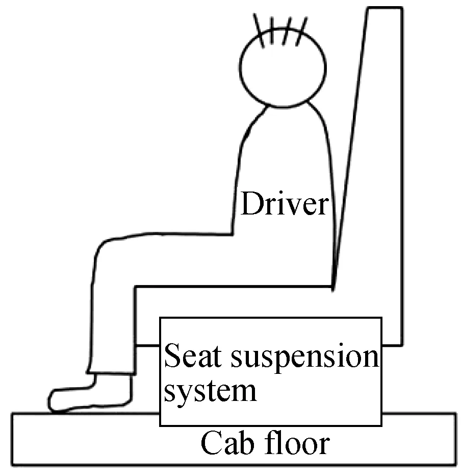
Fig.1 Simplified vehicle seat model
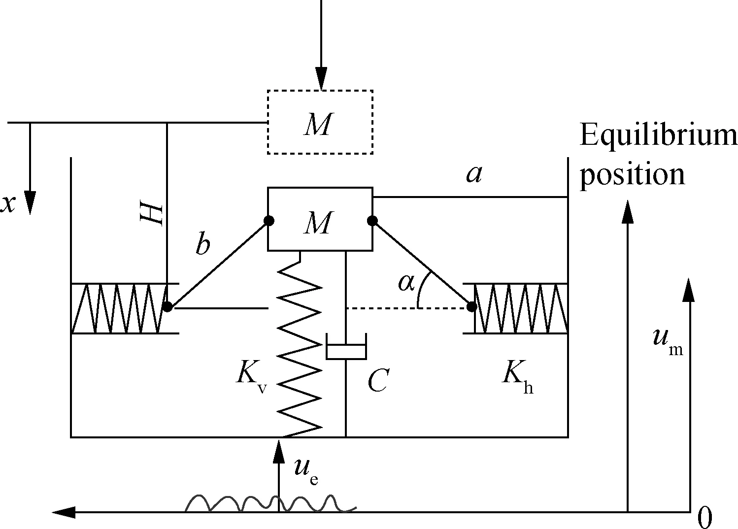
Fig.2 Mathematical model of seat isolation system
The variables in Fig.2 are described as follows:x, displacement in the vertical direction relative to the static equilibrium position of the vibration-isolated objects;KvandKh, vertical and horizontal spring stiffnesses, respectively;b, length of the connecting rod between the horizontal spring and mass block;a, distance from mass blockMto the fixed end of the horizontal spring. The initial state of the mass block is the position of the dashed frame, and each spring of the suspension system is in a compression state during vehicle operation. The dynamic stiffness of the suspension system can be adjusted by changing the above parameters.
The rotation freedom of the seat structure is limited, and the seat can only move in the vertical direction. The vibration reduction amount of the suspension system is affected by different parameters, such as spring stiffness, damping coefficient, length of connecting rod, and the angle between the rod and horizontal plane.
2 Dynamic Model of Seat Suspension
When the system dropsxfrom its initial position, its kinetic energyT, potential energyV, and dissipation functionDare respectively computed as
(1)
(2)
(3)

(4)
Assuming that the spring in Fig.2 is in equilibrium, the deformation length of the horizontal spring is as
(5)
whereL0is the original length of the horizontal spring.
Then, the horizontal force produced by the horizontal spring is computed as
(6)
Next, the horizontal force is converted to the forceFhvin the vertical direction:
(7)
whereαis the angle between the rod and horizontal plane.
(8)
The force produced by the vertical spring in the vertical direction is as
Fv=Kvx
(9)
At this point, in accordance with the principle of virtual work, the vertical-direction restoring forceFof the system is obtained with the following equation:
(10)
Eq.(10) deals with dimensionless variables, where the structural parameters of the system are calculated as
whereF′ is the dimensionless restoring force, andx′ is the dimensionless displacement. Thus, the dimensionless force-displacement relation of the system is obtained as
(11)
Then, the derivation ofx′ is acquired, and the dimensionless dynamic stiffnessK′ of the system is obtained.
(12)
With respect to the seat suspension system, a vertical upward external excitationueis applied at the bottom.uis the displacement of the suspension system relative to the base.umis the absolute displacement of the suspension system in space. The dynamic equation of the system is obtained by the Lagrangian equation.

(13)
The relative displacement, velocity, and acceleration of the isolated equipment relative to the equilibrium position are respectively defined as
z=H-x
(14)
(15)
(16)
where
Mg=KvH
(17)
Substituting Eq.(13) into Eqs.(14)-(17), the new dynamic equation is rewritten as
(18)
3 Analysis of Seat Suspension System
3.1 Parameter analysis of seat suspension system
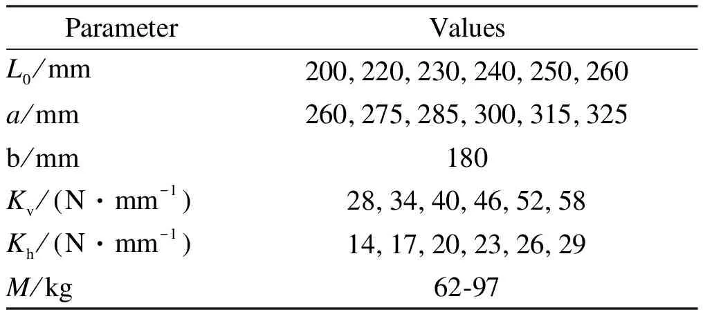
Different parameters will have different effects on the suspension system. The design parameters need to be further determined to evaluate the mechanical properties of the system. Eq. (12) shows that the dimensionless dynamic stiffnessK′ is determined by three-parameter variables, i.e.,α,γ1, andγ2. According to the principle of the single-factor variable method, the structural parameters are discussed as follows (see Tab.1).
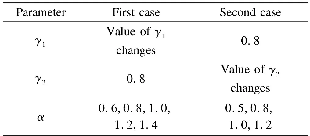
Tab.1 Structural parameters of the model
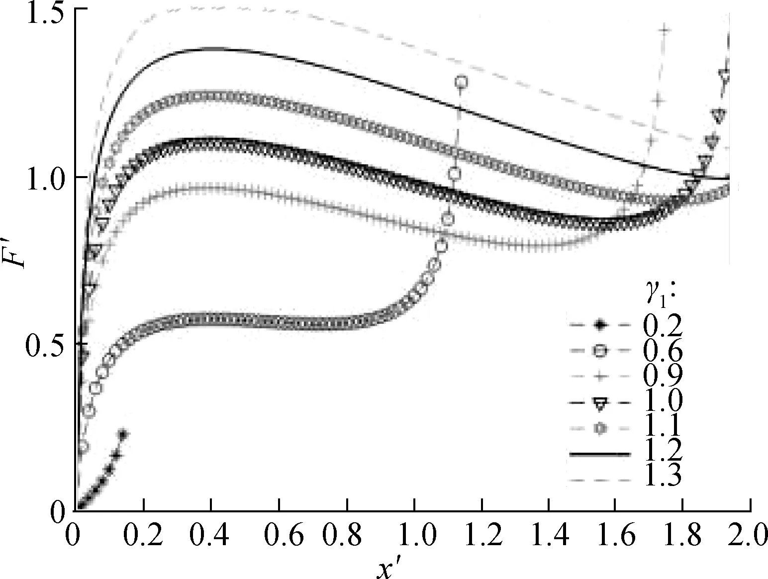
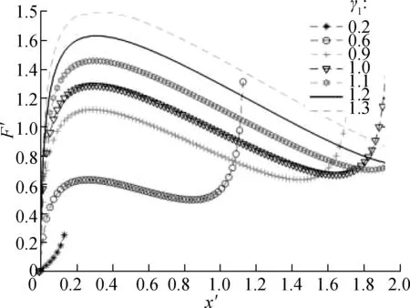
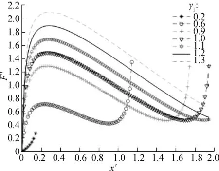
By MATLAB numerical calculation, the force characteristic curve of the system is obtained (see Fig.3). With the increase in displacement, the restoring force curve of the system presents a downward trend, and the structure exhibits negative stiffness characteristics. Whenγ1<1, the occurrence time of the first peak of the curve is short, and the change in the corresponding displacement is small. Whenγ1≥1, the force change trend of the system
(a)
(b)
(c)
in the vertical direction is smooth, which indicates the improved performance of the seat vibration-isolation system and ideal selection of the NSS parameters. The dimensionless forceF′ of the system will peak in a short time when the value ofγ1is especially small. Therefore, this situation should be avoided when designing parameters to prevent affecting the dynamic characteristics of the suspension system. In addition, by contrasting and analysis, the results show that the change inαwill affect the trend of the overall force change of the system. With the increase inα, the trend of the system bearing the force change will accelerate, indicating the increased vibration amplitude of the seat in the vertical direction and the reduced ride comfort of the driver. As a result, the use of a large-valueαis discouraged, and the stiffness of the horizontal spring should be smaller than that of the vertical spring.
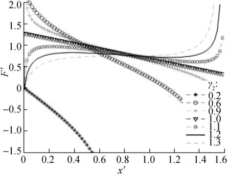
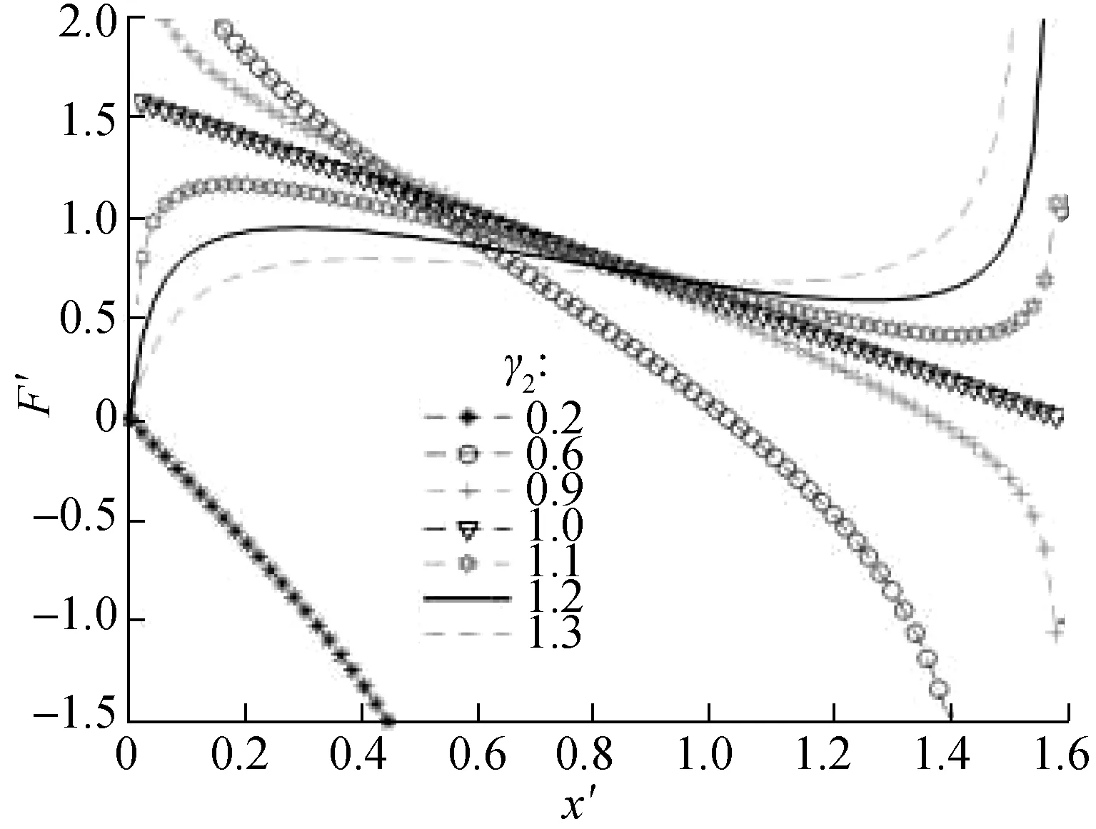
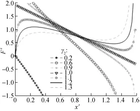
Fig.4 shows the dimensionless force-deflection characteristic curves with different values ofγ2. The results show that whenγ2>1, the curve changes regularly, similar to an elongated sinusoidal curve, along with the existing maximum and minimum peak values. Thus, the dimensionless forceF′ between the two peaks decreases with the increase in displacement, and inversely, in the other positions, the value ofF′ increases with the increase in displacement. However, whenγ2<1, the initial value of the dimensionless forceF′ fluctuates, and the value ofF′ decreases with the increase in displacement.
(a)
(b)
(c)
In this case, although the stiffness of the suspension system is negative stiffness, it is unsuitable for the design of the above negative stiffness model structure. Whenγ2<1, the shape of the stiffness curve is a convex parabola, and the stiffness reaches the maximum peak value in the static equilibrium position. However, at a far enough distance away from the static equilibrium position, the stiffness of the system is always negative, and the vibration-isolation system is in an unstable state. Fig.5 shows the dimensionless force-deflection characteristic curves under different values ofα. With the increase in the value ofα, the flatness of the curve also changes.
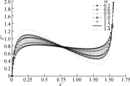
Fig.5 Dimensionless force-deflection curves with various values of α
3.2 Dynamic stiffness analysis of the seat suspension system
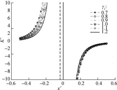
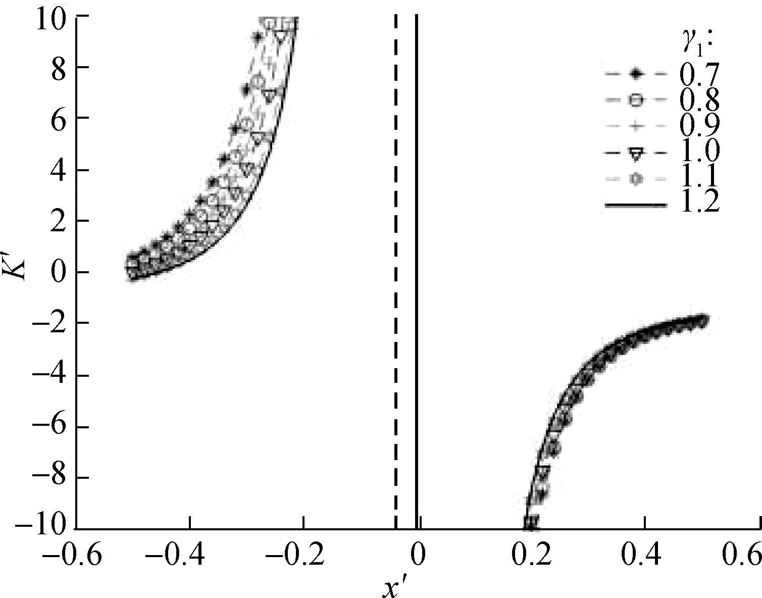
Considering the nonlinear characteristics of the suspension system and multiple design parameters, the dimensionless dynamic stiffness of the system should be used to evaluate the vibration-isolation system to select the appropriate suspension configuration parameters. According to Fig.6, as the value ofγ1increases, the basic outline of the stiffness characteristic curves of the system shows no evident change, whereas changes occur in the curvature of the stiffness characteristic curve. For dimensionless displacementx′<0, when the value ofαincreases, the absolute values of stiffness of the suspension system also increases. For dimensionless displacementx′>0, when the value ofαincreases, the curve moves to the right overall, and the suspension system increasingly deviates from the quasi-zero stiffness. Notably, the value of parameterαshould not be extremely large.
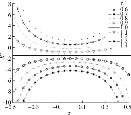
From Fig.7, the corresponding stiffness curves under different values are symmetric at aboutz=0. Whenγ2>1, the dynamic stiffness curve has a concave parabola shape, and the stiffness value at the static equilibrium position is the smallest. Whenα≤1, the stiffness value is always greater than -1. Therefore, the configuration of structural parameters needs to be reasonably selected to ensure that the dynamic stiffness of the static equilibrium position is zero or greater than zero. Additionally, when
(a)
(b)
(c)
γ2=1 andα=1, the dynamic stiffness curve becomes a straight line, and the stiffness value is always equal to -1. This situation shows that the distance from the mass block to the static equilibrium position can be infinite, and the dynamic stiffness of the region above the lineK′=-1 is always less than the static stiffness. However, in the case ofγ2>1, the infinite range from the mass block to the static equilibrium position decreases with the increase inγ2.
Fig.7 also shows several sets of stiffness curves corresponding to different values ofα. Whenα=0.5 andγ2>1, the dynamic stiffness of the system around the static equilibrium position is very close to zero, that is, near quasi-zero stiffness. This condition illustrates that the selection of parametersαandγ2has a certain effect on the stiffness characteristics of the system.
(a)
(b)
(c)
(d)
Fig.8 shows the dynamic stiffness curves of the system under different values ofα. As the value ofαincreases, the minimum value of the dimensionless stiffness curve decreases. Whenα=1, 1.2, the system is close to quasi-zero stiffness, but the concave parabola is closer to the center axis. The correctness of the aboveγ2>1 analysis results is verified again. The larger the range of displacement changes in the suspension system, the better the vibration-isolation effect. To sum up, the design parameters of the suspension system 1≤γ2≤1.3 andα=0.5 are the ideal configuration parameters of the system. However, in the actual design process, obtaining these accurate values is difficult because of the errors in manufacturing and assembly, andγ2<1 may appear. Thus, the quasi-zero stiffness should be satisfied as much as possible during the design.
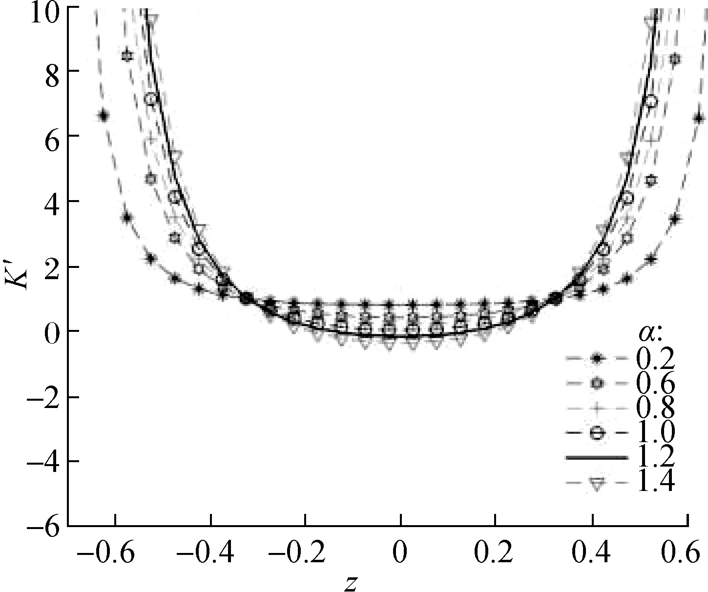
Fig.8 Dynamic stiffness curves of systems with various values of α(z=H-x′)
4 Design Optimization of Cab Seat Suspension System
With a medium loader as an example, the weight of the cab seat is set to 12 kg. The mass range of the human body is 50-85 kg, and the weight range of the mass block in the model is 62-97 kg. Therefore, the fluctuation difference of the mass accepted for the suspension system is 35 kg. According to the design requirements of NSS, the horizontal spring should be forcibly kept horizontally under the static balance. In addition, when keeping the stiffness of the supporting spring unchanged, the maximum floating range is 80 mm in the vertical direction of the designed seat. According to the calculation of the vertical spring stiffness, an additional displacement should be required for the no-load condition as 12.25-20.83 mm, which describes the distance required when the system reaches the equilibrium position at the moment the driver first takes his seat. In this paper, the selected value is a little large, and the stiffness of the support spring is increased moderately to reduce the displacement deviation caused by the input of different system masses.
4.1 Cab floor vibration
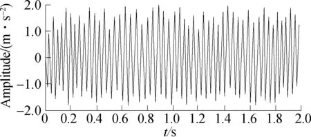
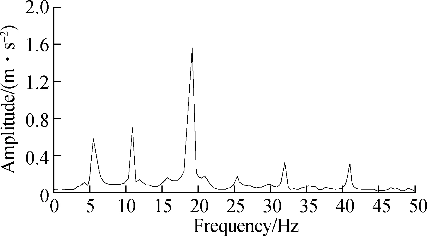
Cab floor vibration is a common phenomenon in construction machinery operations. The vibration source is one of the prerequisites for the simulation of the seat suspension system. The vibration of most construction machinery vehicles is produced by the engine, main/tail rotor, and transmission, which are mechanically connected together. The variable speed motion is carried out by the engine governor, and the vibration is finally passed through the seat to the driver, which results in the whole-body vibration of the driver[5]. In this paper, with the same type of loader as an example, the frequency of the vehicle generating the vibration source is extracted (see Tab.2). The data in the right side of the table can be used to identify the frequency component in the frequency domain diagram, that is, the vibration signal of the cab floor can be reproduced for simulation. In addition, the amplitude of the seat model depends on the external natural conditions during the operation of the construction machinery (such as the soft degree of the road surface, slope turning road, and other road conditions). The excitation source is changeable, and the vibration source propagation path is long, resulting in the external excitation at the connection between the cab floor and the very unstable seat connection. For this reason, the collection of vibration amplitude data is difficult, and thus, the data in other references are referred to[21]. Fast Fourier transform (FFT) is used, and the vibration signal is converted from the time domain to the frequency domain[22]. The amplitude of the frequency component of the vibration signal for the cab floor is reproduced (see Tab.3). Given that the effects of vibration frequencies above 50 Hz on the human body gradually decrease according to ISO 2631, the frequencies above 50 Hz are ignored when the vibration signal of the cab floor is reproduced.
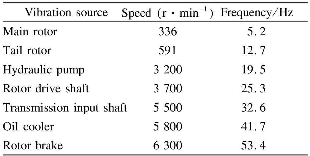
Tab.2 Vibration sources and frequencies of the loader
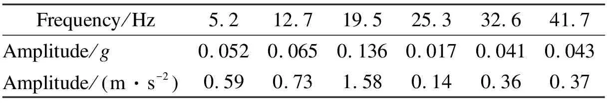
Tab.3 Vibration sources and frequencies of the loader
Fig.9 shows the time domain and frequency domain diagram of the vertical vibration signal of the cab floor. The reproduced signal is simulated as the excitation signal of the floor.
(a)
(b)
4.2 Evaluation criteria for suspension systems
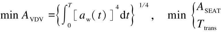
Different methods are used to evaluate system vibrations. At present, the weighted root mean square (RMS) is widely used to evaluate suspension vibrations. However, the use of the RMS method will underestimate the effects of vibration characteristics with numerous peaks[23]. Therefore, the four-time power vibration dose value(VDV) method is used to evaluate the vibration characteristics of the suspension system, because the VDV method is sensitive to the peak value of vibration. Its expression is
(19)
where the unit ofAVDVis m/s1.75or rad/s1.75;aw(t) is the instantaneous frequency weighted acceleration; andTis the duration of the measurement.
To evaluate the effectiveness of the seat suspension system and reduce the vibration transfer amplitude, the frequency weighting function is considered based on the ISO 2631 standard, and seat effective amplitude transmissibility (SEAT), which is defined as follows, is adopted:
(20)
To evaluate the vibration transmissibility characteristics of the NSS suspension system in the frequency domain, we use the following equation to calculate the vibration transmissibility ratio:
(21)
whereGBXis the cross power of vibration signals of the cab floor and seat; andGBBis the auto power of vibration signals of the cab floor in the vertical direction. The calculation equation is as
(22)
whereBandXrepresent the floor and seat bottom vibrations, respectively;τis the time delay between signals; and * is the conjugate signal. The frequency with a transmissibility ratio greater than 1 represents the amplified frequency through the vibration transfer path.
4.3 Optimization model of cab seat suspension system
The design variable refers to the stiffness of the seat suspension system, and the optimization model of low-frequency response for the cab suspension system is as
whereωexcis the excitation frequency;ωnis the natural frequency of the system; andkeqis the total vertical stiffness of the suspension structure. As shown in Figs. 6-8, the value of the dimensionless equivalent stiffness isk′=0.3. The established dynamic model is simulated and calculated by using MATLAB, and the constraint optimization method is used to solve the problem. The design domain contains discrete points, and the optimal solution is searched for. Given the actual engineering design, the parameter values are generally rounded off. Tab.4 shows the structural parameters of the designed seat suspension system.
Tab.4 Parameter setting of seat isolation system
4.4 Simulation results
Based on the above NSS suspension system dynamics model, the displacement and acceleration response curves of the seat are obtained by optimization design (see Fig.10). The vibration signal of the floor is compared with the vibration signal transmitted to the seat. The results show that the response amplitude of the optimized system is remarkably reduced, which indicates that the suspension model based on the NSS effectively reduces the vibration transmitted to the seat through the cab floor. Tab.5 shows the comparison between the vibration characteristics of the cab floor after optimization and those transmitted to the seat. The VDV and RMS method calculation values of the seat in the vertical vibration direction are 0.192 7 and 0.150 6, respectively. Compared with the cab floor vibration, the vibration amplitude and peak amplitude decrease by 86% and 87%, respectively. The finding also illustrates the improved vibration-isolation performance of the seat suspension system. In addition, according to the ISO 2631 standard, the results in Tab.5 show that the driver’s ride comfort and vibration environment have been substantially improved.
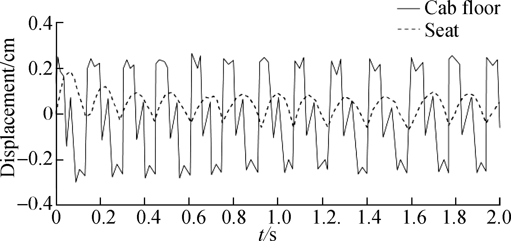
(a)
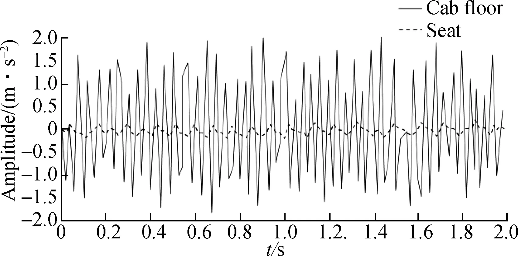
(b)
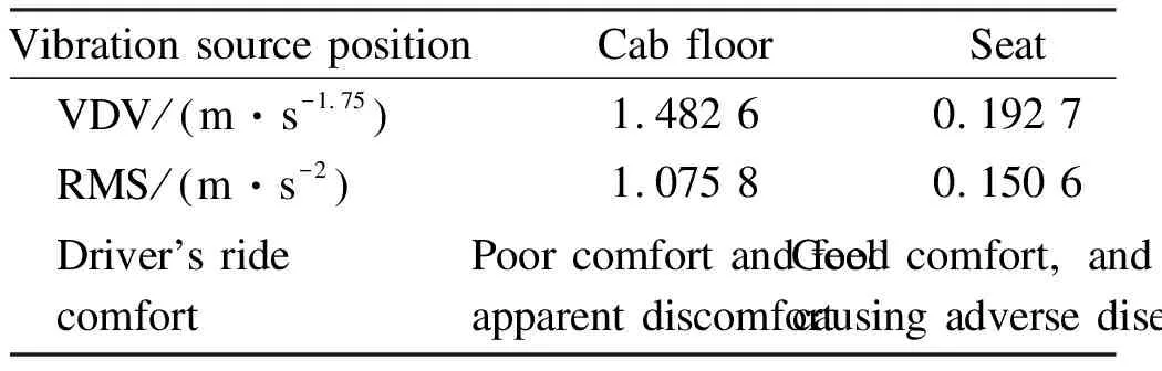
Tab.5 Vibration characteristics of cab floor and vibration characteristics transmitted to the seat after optimization
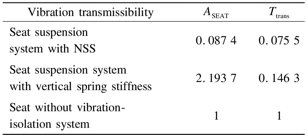
Given that VDV and RMS only reflect the main characteristics of vibration signals, the performance of the suspension system can be evaluated intuitively by calculatingASEATandTtrans. Tab.6 presents the evaluation results obtained after the optimal design. The values ofASEATandTtransare 0.0874 and 0.0755, respectively. Compared with the suspension system with vertical spring stiffness only, the vibration transmissibility rate of the seat decreases, which illustrates that the NSS suspension system has good vibration-isolation performance.
Tab.6 Vibration sources and frequencies of loader after optimization
To analyze the difference between the vibration frequency transmitted to the driver and the resonance frequency of the human body, we analyze the vibration characteristics of the seat in the frequency domain in this paper. Fig.11 shows the vibration FFT spectrum transmitted to the driver through the suspension structure. The results show that for the optimization model, the vibration frequency transmitted to the driver changes is within 1-50 Hz, in which the minimum frequency value is 4.7 Hz. Given that the human body is sensitive to certain special frequencies, the driver or certain parts of their body will suffer from diseases when they are exposed to such vibrational frequencies for a long time. Human body vibration has a critical frequency of 4 Hz[11,24-25], and 4.7 Hz is very close to this critical frequency. Given the internal damping of the human body and the low amplitude transmitted to the seat, the frequency of 4.7 Hz will not cause physical discomfort to the driver. Moreover, none of the other frequency values in the spectrum approach the other critical frequency values of the human body. To sum up, the design of the seat suspension system has no adverse effect on the health of the driver after being vibrated. Fig.12 shows the vibration spectrum contrast of the cab floor and seat suspension system. The acceleration amplitude is evidently reduced, and the spectrum diagrams of the seat and the cab floor are notably similar. These findings illustrate that no frequency regulation occurs in the vibration transfer path.
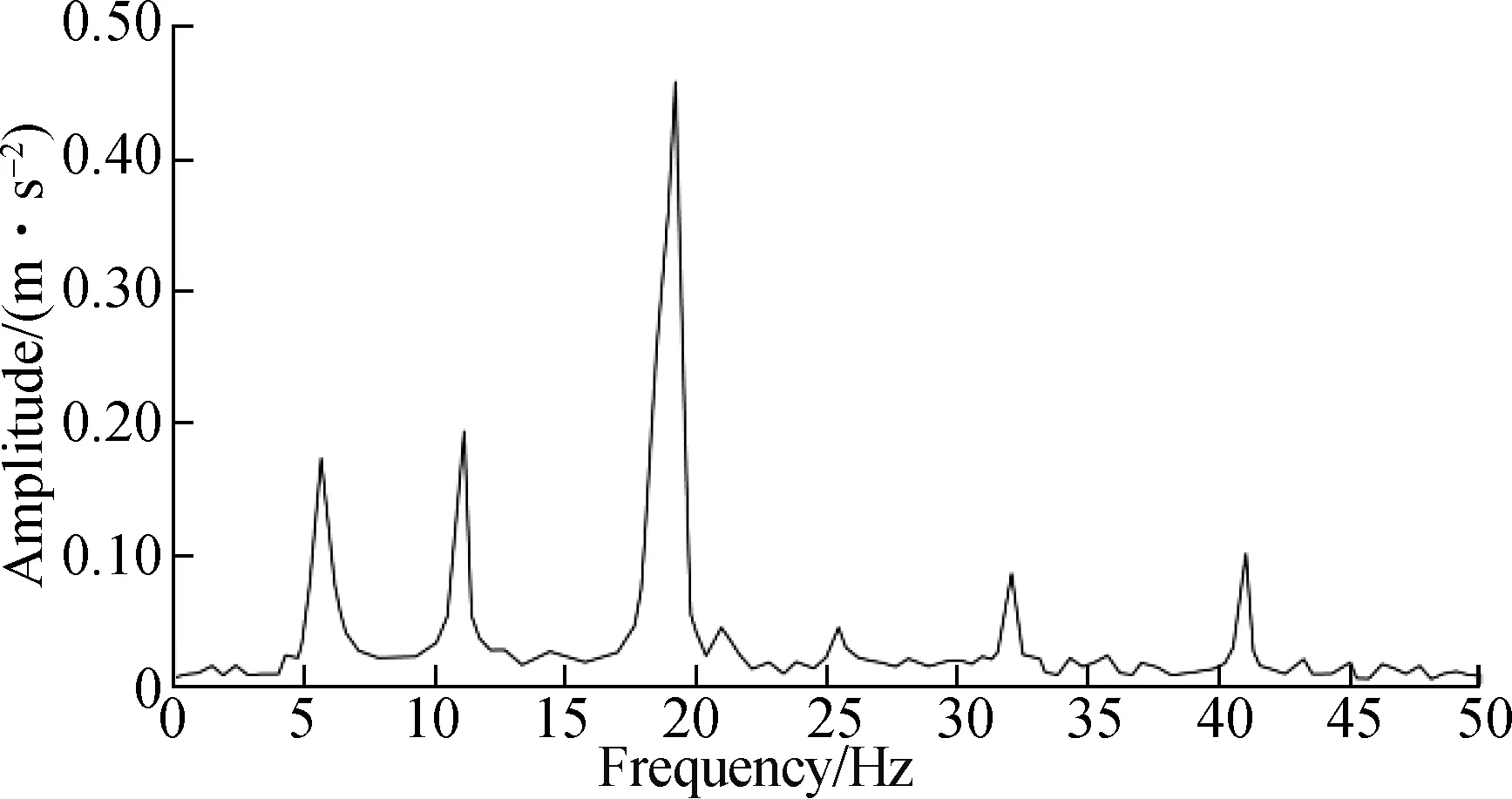
Fig.11 Vibration spectrum of the optimal model of the seat suspension system
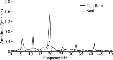
Fig.12 Comparison of vibration spectrum between the cab floor and seat (transmitted to driver)
To study the influence of different loads and uncertainty on the performance of the suspension system, based on the optimization model, we carry out simulations based on different driver weights and the uncertainty of stiffness coefficients. Tab.7 shows the comparative analysis results. TheASEATvalues of the seat suspension system are given in the table. When the loadP≥ 80 kg, the value ofASEATincreases with the increase in uncertainty of the spring stiffness coefficient. The vibration transmissibility rate also increases. When the loadP<80 kg, an increase in the uncertainty of the spring stiffness factor first leads to a smallASEATvalue. This finding indicates the improved performance of the suspension system. Then, theASEATvalue increases, and the vibration-isolation performance of the system decreases gradually.
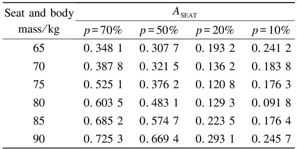
Tab.7 ASEAT values of NSS suspension system under different uncertainties
Tab.8 shows theTtransvalues of the seat suspension system under different percentages of uncertaintyp. The results show that as the uncertainty of the spring stiffness coefficient increases, the value ofTtransincreases gradually, and the vibration-isolation performance of the seat decreases. Different evaluation criteria are used betweenASEATandTtransvalues. TheASEATcalculation results express the reduction of the vibration amplitude itself, whereas theTtransvalues emphasize the relative dependence between the signals of excitation and seat vibration. Furthermore, the results from Tabs. 7 and 8 show that the performance of the suspension system exhibits no significant change with the variations in load mass, which indicates that any change in the driver’s weight in the range of 65-90 kg has no effect on the performance of the seat suspension system. To sum up, regardless of the uncertainty of the stiffness coefficient and changes in the load mass, the suspension structure still presents a good performance.
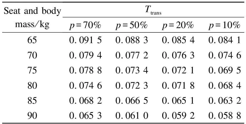
Tab.8 Ttrans values of NSS suspension systems under different uncertainties
5 Conclusions
1) A cab seat suspension system based on the NSS is designed in this paper, and its nonlinear dynamic model is established. The different structural parameters of the system and its influence on the dynamic stiffness characteristics are respectively analyzed. The ideal configuration parameter range and the final value of the suspension system are obtained.
2)The optimization model for the seat suspension structure of construction machinery cabs is put forward. By simulation and comparative analysis, the vibration transmissibility is studied. The results show that the acceleration and displacement amplitudes of the optimized seat suspension system are evidently reduced. According to the ISO 2631 standard, RMS and VDV method calculation values in the vertical vibration direction are reduced by 86% and 87%, respectively. The vibration transmissibility rate,ASEATandTtrans, are also reduced.
3) Through the analysis of the frequency domain response of the seat suspension system, the comparison results show that in accordance with the ISO 2631 standard, the peak frequency of the vibration transmitted to the driver avoids the key frequency, which can easily cause human resonance. The influences of the uncertainty of stiffness coefficients and different driver weights on the suspension system are discussed. The study results show that the change in a driver’s weight in the range of 65-90 kg has no effect on the performance of the seat suspension system. The seat suspension system with NSS exhibits good vibration-isolation performance, improving the working environment of the driver and the ride comfort of the seat.
杂志排行

Journal of Southeast University(English Edition)的其它文章
- Effects of crankpin bearing speed and dimension on engine power
- A method for workpiece surface small-defect detection based on CutMix and YOLOv3
- Three-dimensional visualization interactive system for digital twin workshop
- Transformer-like model with linear attention for speech emotion recognition
- Non-inverting buck-boost DC-DC converter based on constant inductor current control
- No-reference blur assessment method based on gradient and saliency