Three-dimensional visualization interactive system for digital twin workshop
2021-07-13ZhangQingleiYangZhiweiDuanJianguoLiuZhenQinJiyun
Zhang Qinglei Yang Zhiwei Duan Jianguo Liu Zhen Qin Jiyun
(School of Logistics Engineering, Shanghai Maritime University, Shanghai 201306, China)
Abstract:To improve the human-physical-virtual coordination and integration of the digital twin workshop, 3D visual monitoring and human-computer interaction of the digital twin workshop was studied. First, a novel 6D model of the 3D visualization interactive system for digital twin workshops is proposed. As the traditional 5D digital twin model ignores the importance of human-computer interaction, a new dimension of the user terminal was added. A hierarchical real-time data-driven mapping model for the workshop production process is then proposed. Moreover, a real-time data acquisition method for the industrial Internet of things is proposed based on OPC UA(object linking and embedding for process control unified architecture). Based on the 6D model of the system, the process of creating a 3D visualization virtual environment based on virtual reality is introduced, in addition to a data-driven process based on the data management cloud platform. Finally, the 6D model of the system was confirmed using the blade rotor test workshop as the object, and a 3D visualization interactive system is developed. The results show that the system is more transparent, real-time, data-driven and more efficient, as well as promotes the coordination and integration of human-physical-virtual, which has practical significance for developing digital twin workshops.
Key words:digital twin workshop; three-dimensional visualization; human-computer interaction; data driven; OPC UA (object linking and embedding for process control unified architecture)
A new generation of information technology (such as the Internet of Things, cloud computing, big data, and artificial intelligence) has been attracting considerable attention. Many countries have proposed smart manufacturing plans, such as Industry 4.0, industrial Internet, “Made in China 2025” plan, service-oriented manufacturing, and cloud manufacturing. Intelligent manufacturing has higher requirements for integrating physical and information space, for which a digital twin solution has been proposed[1-4].
Digital twins create physical, digital models and use real-time data-driven models to simulate the actual behavior of physical entities while performing virtual-real interaction, data fusion analysis, simulation, fault prediction, and decision-making[5-6]. Digital twin technology has been applied in the field of industrial manufacturing to provide a product design and production optimization process, as well as equipment failure prediction and maintenance[7-9]. The application of digital twins can integrate physical space and virtual space to realize product lifecycle management[10-12].
Recently, researchers, scientific institutions, and enterprises from various countries have been conducting theoretical and technical discussions of the research of digital twins in the workshop and manufacturing process. Many domestic and foreign researchers have been researching and practicing this and have achieved certain results.
For theoretical research on digital twins,Tao et al.[13-14]proposed the concept and operation mode of the digital twin workshop, introducing its 5D model. Zhuang et al.[15]analyzed the possibility of implementing digital twins in the product design stage. Liu et al.[16]proposed a rapid custom design method for personalized production lines based on digital twins. D’Amico et al.[17]proposed a digital twin framework to meet the needs of regular maintenance of complex engineering systems (CES). Wu et al.[18]proposed a digital twin conceptual modeling method based on a 5D digital twin framework to express the complex relationship between digital twin objects and their attributes. O’Sullivan et al.[19]introduced the maintenance of digital twins into large-scale manufacturing plants and proposed a digital twin framework. Yildiz et al.[20]introduced the concept and architecture of a virtual factory based on a digital twin. Liu et al.[21]proposed the architecture of the digital twin system in the workshop production process. Schroeder et al.[22]completed the data exchange between the physical world and the digital space based on digital twin technology.
In the area of 3D visualization monitoring for the workshop, Zhu et al.[23]proposed an AR application that can interact and manage digital twin data at the same time. Qiu et al.[24]proposed an online simulation monitoring method for the automatic spray operation of an aircraft based on digital twin technology. Oyekan et al.[25]created a virtual environment based on Unity3D software to realize the 3D visualization of human response to robot actions. Zhuang et al.[26]developed a DT-based workshop operating state visual monitoring and prediction system (DT-VMPS). Falah et al.[27]studied how to use digital twin to integrate physical devices with their virtual models to monitor the process. Liu et al.[28]proposed a digital twin modeling method based on the principle of bionics. Hutabarat et al.[29]examined the fusion method of 3D scanning technology and discrete event simulation, as well as reflected it in the virtual reality environment. Li et al.[30]designed the real-time monitoring of the manufacturing workshop. Cao et al.[31]proposed a real-time data collection and visual monitoring method for discrete manufacturing workshops based on radio frequency identification (RFID) technology. Huang et al.[32]fused radio frequency identification (RFID) data with monitoring rule models to obtain production status and abnormal information. Zong et al.[33]proposed a multi-robot monitoring system based on digital twin for simulation. Zhao et al.[34]proposed a multi-level 3D visualization monitoring mode and real-time data-driven virtual workshop operation mode. Jiang et al.[35]built a virtual workshop condition monitoring system and verified it on Uniy3D. Zhou et al.[36]proposed a three-dimensional visual monitoring system for workshops based on digital twins.
In terms of human-computer interaction,Li et al.[37]established the industrial security and control architecture of the digital twin system for human-computer interaction. Qiu et al.[38]studied the characteristics of augmented reality (AR) and digital twin (DT) technologies in virtual reality fusion and human-computer interaction control. Ma et al.[39]believe that traditional human-computer interaction efficiency and safety still cannot meet the requirements of intelligent manufacturing and emerging technologies. Ke et al.[40]designed an enhanced interaction framework for digital twins based on VR, AR and MR. Shuai et al.[41]believe that a new generation of intelligent interfaces that combine man-machine and virtual reality is a significant feature of intelligent manufacturing.
For realizing digital twins, only the extensive use of human-computer interaction can give full play to the advantages of digital twins in the production process. Human-computer interaction has become one of the key technologies in realizing intelligent manufacturing[42]. Human-computer interaction primarily studies human-computer interaction interfaces (such as software interfaces and control panels) to control operations and interactive methods of machines or equipment[43]. Currently, virtual reality technology has brought new developments to human-computer interaction, and the visualization of digital twins is continuously improving[44].
In summary, at present,certain results have been achieved about the design of the digital twin workshop system and the 3D visual monitoring of the production process. However, the following problems still exist:
1) Digital twin workshops have a low degree of human-physical-virtual coordination and integration. There are relatively few human-computer interaction research and applications for digital twin workshops. The importance of personnel in digital twin workshops has been neglected when designing a 3D visual monitoring system for workshops based on digital twins. The lack of diverse human-computer interaction designs results in insufficient automation and digitization of the workshop and a poor user interaction experience.
2) Lack of an efficient and universal real-time data-driven mapping model, the data collection, data storage, data-driven, and data feedback processes are not clear enough. It is relatively difficult to implement different types of manufacturing workshops, and real-time production mapping of virtual workshops is poor.
To address these problems, A novel 6D architecture of a 3D visualization interactive system for digital twin workshops has been proposed. On the one hand, the architecture takes data management as the core and improves the data interaction and fusion capabilities among the various parts of the entire system. On the other hand, compared with the traditional digital twin 5D model, the user terminal is added as a new dimension. Through the human-computer interaction of the user terminal, the user can perform operations such as browsing, query, simulation, and training to help solve the dangerous and complex production process control, help reduce the on-site participation of personnel in the production process, and avoid the inconvenience of equipment operation control. At the same time, a hierarchical real-time data-driven mapping model for the workshop production process has been proposed. This model builds a closed-loop data drive, including the OPC UA-based industrial Internet of things (IoT) data collection, physical and virtual spatial information logical conversion, data management cloud platform, data drive and data feedback. This model is suitable for the current manufacturing workshop, the data-driven real-time performance is superior, and it can realize data feedback control of the physical workshop. In addition, the process of creating a 3D visualization virtual environment based on virtual reality has been introduced. At the same time, the development and invocation of external algorithms and simulation functions have been introduced, so as to provide support for production optimization and failure prediction of the physical workshop. Finally, the system was verified with the blade rotor test workshop as the object.
1 3D Visualization Interactive System Framework for Digital Twin Workshop
Based on the digital twin 5D model, this study comprehensively considers human-computer interaction, virtual environment fidelity, real-time data mapping and model driving, and improvement of the accuracy of virtual simulation. The novel 6D model of the 3D visualized interactive system with data management as the core has been proposed. It includes physical space, virtual environment, data management, user terminal, external service, and connection. The dimension of user terminal has been added, as compared with the 5D model of the digital twin workshop. The user’s control of the entire system has been improved through the design of human-computer interaction on the user terminal. Fig.1 shows the 6D model of the 3D visualization interactive system for the digital twin workshop.
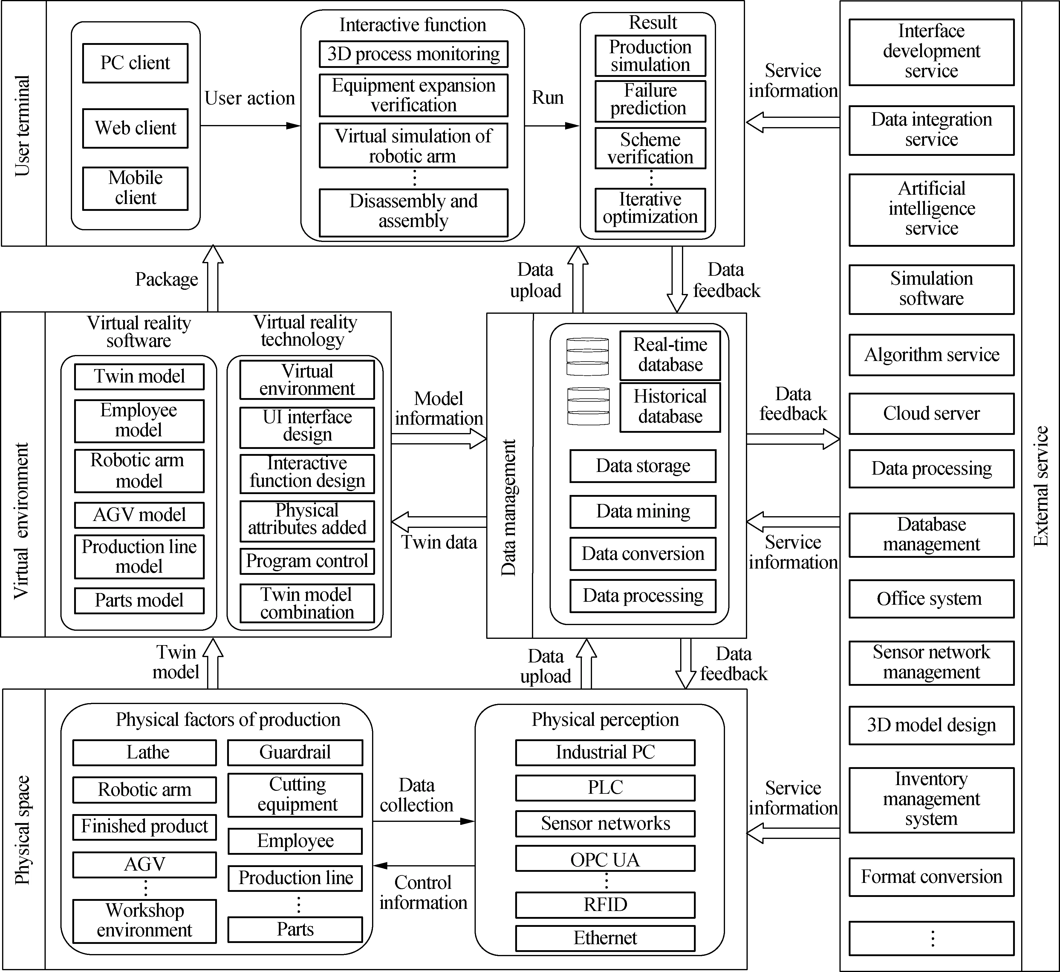
Fig.1 Three-dimensional visualization interactive system architecture for digital twin workshop
1) Physical space is the primary body of the entire system, primarily involving various production factors. These factors include entities and industrial IoT. Entities include robots, machine tools, employees, production lines, and parts. The IoT includes sensors, industrial computers, programmable logic controllers, RFID, data collectors, and other perception and control equipment. The combination of the IoT and various production factor entities can realize real-time perception and intelligent control of the physical space production process; moreover, real-time data transmission and reception networks can be established based on the industrial IoT.
2) Virtual environment is a digital mapping of physical space. It primarily achieves a high-fidelity reproduction of physical equipment, phenomena, motion, environment, and interactive interface design, involving data mapping and model mapping of physical space. Model mapping is a 3D digital model of physical production factor entities, including structure, physical attributes, geometric constraints, and combination relationships. Data mapping comes from the real-time data of the physical production process stored in data management, including equipment data, personnel data, operating data, action data, product data, environmental data, and control data.
3) Data management is used as a unified data management platform. It is used to realize the classification and fine management of data of different types, different structures and different sources. Data management has an external data access interface, which can build connections with various parts so as to realize data sharing and data drive to the virtual environment.
4) User terminal is a user-oriented, 3D visualization interactive platform. The terminal has been packaged and released based on the virtual twin environment, and the terminal synchronizes the real-time operating status of the physical space. There are three types of terminal releases: Computer, web, and mobile. The user terminal has a human-computer interaction interface and functional modules, which can perform the 3D process monitoring, equipment information query and expansion verification, simulation, and other functional operations.
5) External service is a service support platform. To meet the requirements of all-round services, external service can be a collection of multiple types of sub-services, or support for a single sub-service, owing to the diverse needs of the workshop sub-requirements to design and match sub-services. The connections with sub-services are usually established based on technologies such as communication. Among them, for the physical environment, external service can provide service support such as three-dimensional model design and optimization, sensor network management, and office auxiliary systems; for data management, external service can provide data processing technology, database construction, cloud servers, algorithms, and simulation software. For the user terminal, external service can provide service support such as interface development, data integration, algorithm, simulation software, and database access; for the virtual environment, external service can provide data service support through data management.
6) Connection is the key to the data exchange of the entire 3D visualization interactive system. The connection has been built with data management as the core. Data are the key to the operation of the entire system. Through the following four data closed-loop connections, the connection and real-time data sharing among various parts can be realized. The four data closed-loop connections have been expressed as follows: ①Physical space, which uploads real-time production process measurement data through physical perception, and various controllers in physical perception receive feedback data to generate control information to adjust the production process. ②Virtual environment accesses the data of the data management to drive the imported physical space three-dimensional digital model to complete data query and visualization, and to feedback abnormal data of various equipment in the virtual production process at the same time. ③User terminal can establish a real-time connection with the data management through the package script, providing data support for the three-dimensional visualization monitoring and interactive functions of the production process. The user terminal can feed back the results of some interactive functions and simulation guidance information. ④External service provides various service information for physical space, data management, user terminal, and virtual environment. Among them, physical space, data management, and user terminal establish connections with external service through Application Programming Interface (API), Software Development Kit (SDK), TCP/IP and other technologies. The virtual environment has been created based on virtual reality development software; it cannot directly establish a connection with the software and system in external service to obtain real-time data. Therefore, data management has been used as an intermediary to provide fast data services. Physical space, data management, user terminal, and virtual environment apply the service information obtained from external service; they will upload the data to data management, and then feed the data back to external service through integration and analysis.
2 Creation of 3D Visualization Virtual Environment Based on Virtual Reality
The virtual environment is a digital copy of each entity element, dynamic process, and production environment of the physical space. A virtual environment has been established for the entities in the physical space to reproduce the physical environment, objects, and actions. The virtual environment construction process is shown in Fig.2. The physical space mainly includes production elements

Fig.2 Virtual environment construction process
(i.e., products, materials, equipment, personnel, industrial robots, and controllers) and production environment elements. The virtual environment has been created based on the geometric model size of each production element and the production environment, including three-dimensional modeling, physical attribute setting, motion logic control, virtual scene layout, interactive interface, and program control.
2.1 Creation of 3D models of production factors in physical space
The virtual environment establishes a corresponding three-dimensional model based on the entities of each production factor in the physical space. This model has been used to ensure that the virtual twin environment is consistent with the entity in terms of geometric size, spatial location, and physical factors. The physical space has been divided into categories such as equipment, personnel, and environment. Three-dimensional models of production factors contained in each category have been created. The method of creating three-dimensional models by category can improve the efficiency of model creation. The production factor model of the physical space is shown in Fig.3. It includes the processing equipment model, transportation equipment model, assembly equipment model, personnel model, material model, space environment model, and space perception equipment model.

Fig.3 Models of production factors in physical space
2.2 3D model physical property setting
The design of virtual environment comprehensively considers the realism and immersion of the 3D visualization scene. Virtual reality software has been used to develop a virtual twin environment, which can reduce the amount of underlying system development while ensuring the fidelity of the virtual environment. The virtual reality software can optimize and render the imported 3D model, realize the layout of the virtual scene, switch the camera perspective, detect physical constraints, particle effects, and external access, and enable system integration release. In the virtual twin environment, geometric transformations and rotation changes have been input into the model. Also, physical attributes such as rigid bodies and colliders have been input into the model for simulating the actual motion state of each production factor. Thus, the logical control of the model movement has been realized, and the physical phenomenon that violates reality has been avoided.
2.3 Human-computer interactive function design
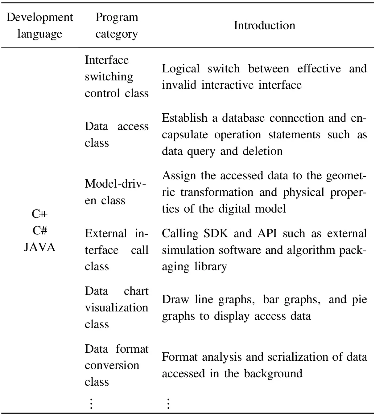
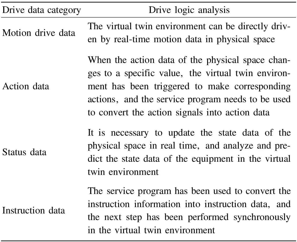
Compared with the traditional two-dimensional workshop electronic billboard, the UI interface of the system has been designed in a virtual environment to provide a three-dimensional real-time process monitoring and interactive interface. Human-computer interaction mainly includes the realization of geometric transformation and the response to external input events. The geometric transformation includes three forms of translation, rotation, and scaling. External input events include mouse, keyboard, and VR devices. The interactive functions are shown in Tab.1.
The realization of the human-computer interaction function of the user terminal requires the design of a control program in the virtual environment. It can be accessed with external algorithms, software, etc. by writing API.

Tab.1 Virtual environment human-computer interactive function
2.4 Virtual environment program logic control design
The realization of user terminal human-computer interaction requires program control design in a virtual environment. Virtual reality development software uses general object-oriented computer languages (such as C++, C#, JAVA, etc.) for programming, which facilitates system development. For example, the development of API and TCP/IP enables access to external algorithms and software. According to the interactive function category of the virtual space, the control script can be divided into the following types: interface switching control, data access, model-drive, and external interface call. The program control categories are shown in Tab.2.
3 Real Time Data Driver Based on Data Management Cloud Platform
Virtual environment to physical space production process mapping has been used for ensuring the integration of virtual and real. The virtual environment realizes data exchange through data management and physical space. The virtual environment acquires the data of the physical space to complete real-time perception, model-driven, and interactive functions. The physical space obtains virtual space data to adjust the production process. Therefore, the data management is the basis for completing the mapping and data driving of the entire system.
Tab.2 Program control category
The mapping from virtual environment to physical space includes five main parts: Product, equipment, personnel, system and environment. The mapping from virtual environment to physical space needs to build a closed-loop data driver. The hierarchical real-time mapping logic model of the workshop production process is shown in Fig.4, which mainly includes physical space, industrial IoT real-time data collection, database, virtual space, interactive terminal, and data integration feedback. Among them, the collected data needs to be formatted before data storage. The virtual space completes the data drive by accessing the database to obtain data. Finally, the data such as the simulation results of the interactive terminal are integrated and fed back to the physical space.
3.1 Real time data acquisition of industrial Internet of things based on OPC UA
For the twin data collection, the measurement data such as control signals and operating status from the physical space production site should be collected. In view of the different information collection methods of each production element in the physical space, the information of the physical space can be divided into the following seven categories: motion status information, action information, environmental status information, controller command information, office auxiliary system information, equipment status information, and product information. Physical space information categories are shown in Tab.3.
Due to physical space including multiple types of data information, the OPC UA data communication network architecture has been oriented to safe and reliable IOT for
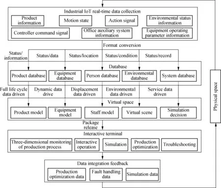
Fig.4 Hierarchical real-time mapping logic model of the workshop production process

Tab.3 Physical space information categories
workshop. OPC UA supports built-in data, cross-platform operation, and can provide a unified address space and services. The UA server has been deployed on the production equipment side, and has been connected to the programmable logic controller (PLC), RFID, sensors, and data collectors through Ethernet. Communication between PLC and physical equipment needs to define input/output ports and equipment motion parameters. The UA server accesses the IP address and port of the PLC to obtain real-time updated physical equipment operating data. The UA server is weaker than the database in terms of data storage and processing. Therefore, the UA server node is read through the client program to obtain the data and store it in the database. The real-time data acquisition process based on OPC UA is shown in Fig.5.
3.2 Logical conversion model of physical space information based on multithreading
The virtual environment represents space in digital form, and its data-driven logic is different from the signal logic of physical space[21]. Therefore, it is necessary to perform format conversion and logical processing on a large number of drive signals and data obtained from the physical space before data storage. This is preparation for for the next step in the virtual environment in which data for various levels of data drive are called. The logical conversion model of physical and virtual spatial information is shown in Fig.6.
The model data or signals collected in the physical space generally exist in four forms: Boolean, integer, real, and string[21]. In contrast to the information types of the physical space, multi-threading technology can be used when the information format conversion has been performed, and the multi-type information format can be received, converted, and stored at the same time. Moreover, the information after the conversion of the physical space format can be divided and returned. The category of the driving data of the virtual space is shown in Tab.4.
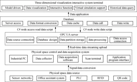
Fig.5 Real-time data collection process based on OPC UA

Fig.6 Logical conversion model of physical and virtual spatial information
3.3 Data management cloud platform creation
We built a data management cloud platform based on cloud servers and databases to complete data storage; open database remote access permissions can meet the remote data access requirements of user terminal and virtual environment. According to the real-time status and operation process of the physical space, the five main bodies of product, equipment, personnel, system, and environment, and their relations, have been abstracted, and the subordinate relations of each main body have been included. The data collected in the production process has been selected, stored, catalogued, and indexed through product database,equipment database, personnel database, environmental database, and system database to realize the refinement of movement data, status data, and instruction data of each subject management.
Tab.4 Driving data categories for virtual space
3.4 Real time data drive
In the real-time driving process, based on the physical space historical operating data, the user terminal interactive function operating results, and external simulation data, these data have been integrated and analyzed to obtain comprehensive data. Based on the OPC UA protocol, through the write operation to the UA server node, the comprehensive data is transmitted to the controller (PLC, industrial computer, etc.) connected to the physical space equipment and the operating staff to complete the data integration feedback.
4 Implementation and Verification of 3D Visualization Interactive System for Digital Twin Workshop
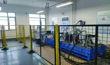
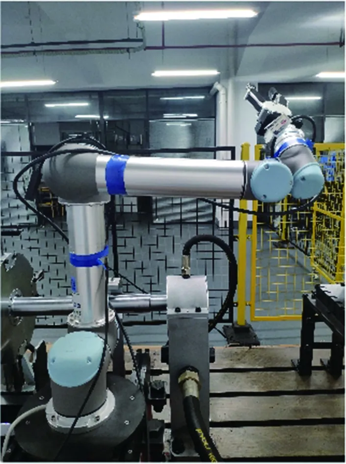
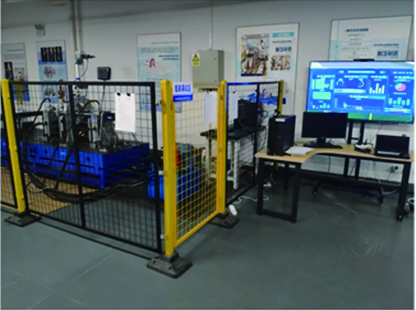
For the present paper, a blade rotor test workshop was used as a case study to build a 3D visualization interactive system for a digital twin workshop. The test workshop contained a blade rotor test bench, power units, data acquisition units, control units, lubrication units, assembly units, communication units, test environments, storage areas, and other elements. The physical environment of the blade rotor test workshop is shown in Fig.7 (b).
In order to realize the three-dimensional visualization and human-computer interaction of the blade rotor test workshop, three-dimensional modeling and light weighting were carried out based on Solidworks and 3DsMax. The virtual twin environment was created by Unity3D virtual reality software, including interface design, physical attributes, and control script design. Data acquisition was completed based on laboratory PLC and the data acquisition system, and data transmission was completed through OPC UA protocol. The data management platform was designed based on the MySQL database to read and store data on the UA server nodes. Based on Matlab robotic arm simulation function .NET platform conversion and packaging, and through Socket communication, the robotic arm virtual environment assembly simulation was carried out. The three-dimensional visualized interactive system architecture of the steam turbine blade rotor test workshop is shown in Fig.8.
(a)

(b)
4.1 Realization of 3D model of blade rotor test workshop
The three-dimensional model of the blade rotor test bench components is given in Fig.9. The test bench includes equipment and components such as drive motors, support tables, bearing bases, blades, spindles, rotors, blisks, and UR5 robotic arms, etc. In view of the complexity of the test bench, the method of classification and hierarchy was adopted for modeling, and SolidWorks and 3DS MAX software were used to create and reduce the weight of the 3D model of the test bench. At the same time, the storage area, monitoring area, console and other physical test workshop environment elements were modeled.
4.2 Realization of the virtual environment in blade rotor test workshop
The three-dimensional model of each element of the blade rotor test workshop was converted to .FBX format and imported into the virtual twin environment created by Unity3D. After the three-dimensional model was imported, the combination and layout were carried out. At the same time, materials and physical attributes such as metal, plastic, wood, rigid body, and collider were added. Using the above methods to process the three-dimensional model, the virtual twin environment of the test workshop can ensure that it is consistent with the physical rotor test bench in terms of geometric dimensions, physical structure relationships, and kinematic characteristics. The virtual twin environment of the blade rotor test workshop is shown in Fig.10.
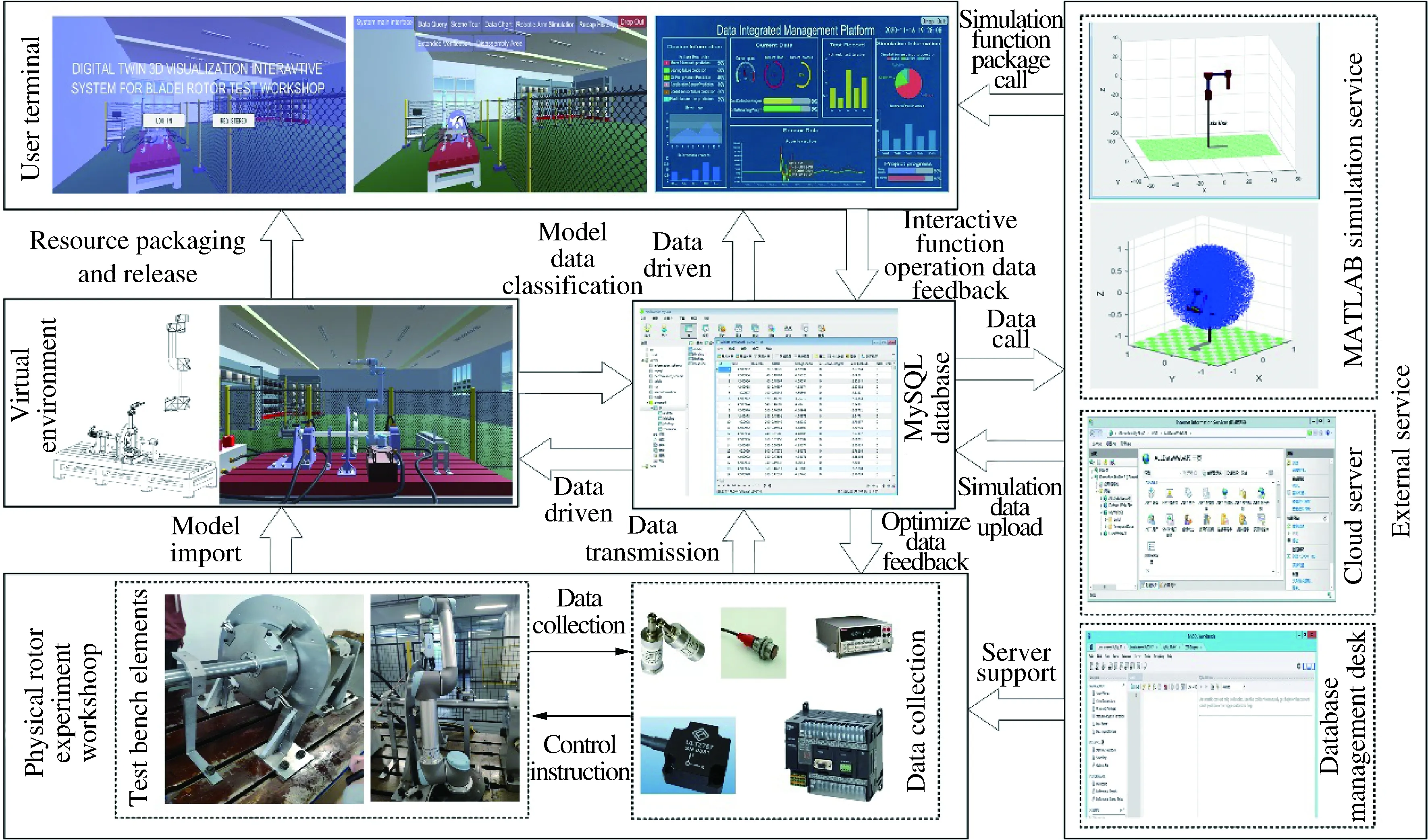
Fig.8 Three-dimensional visualized interactive system architecture for the blade rotor test workshop
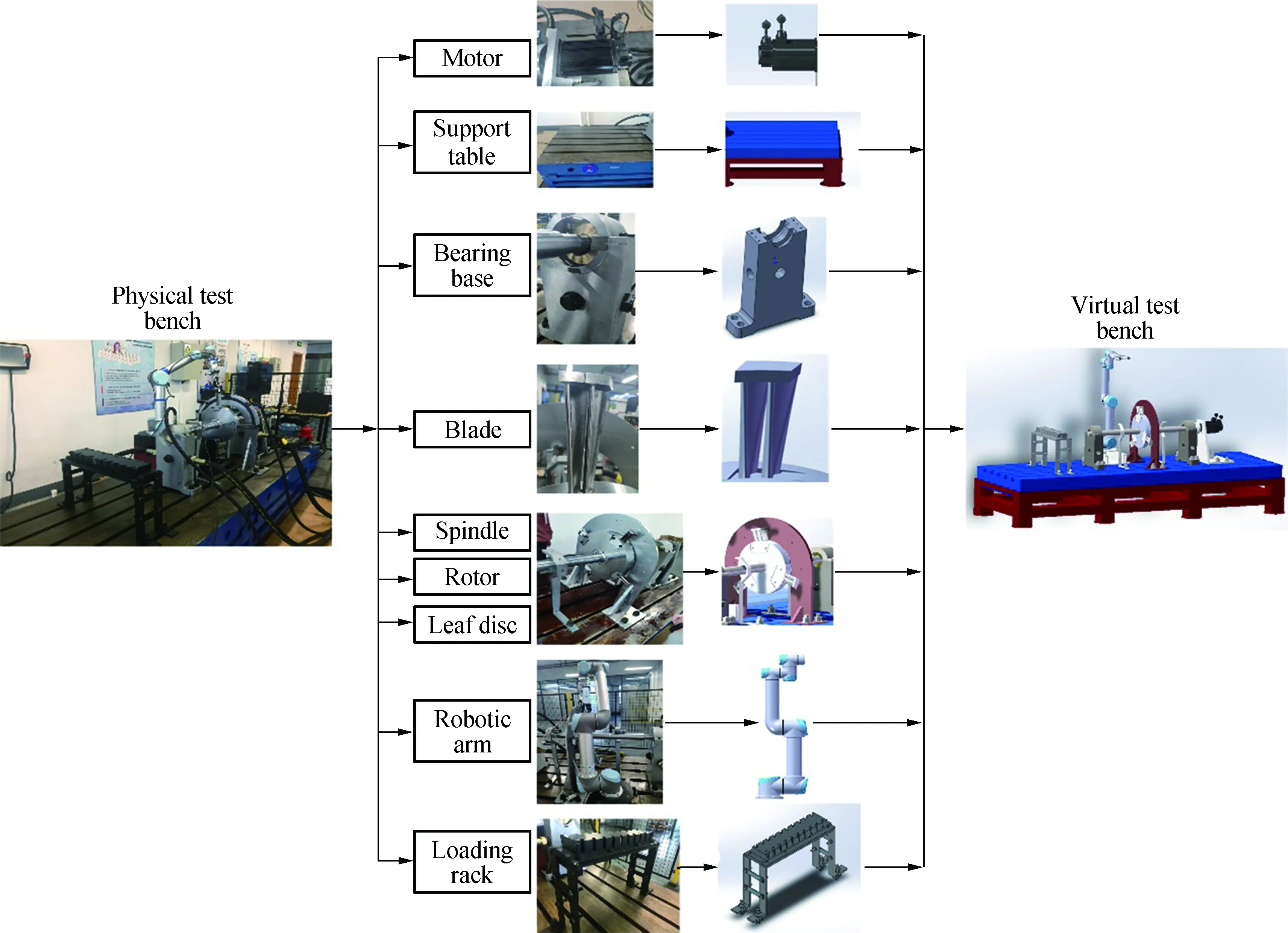
Fig.9 Creation of a three-dimensional model of the components of the blade rotor test bench
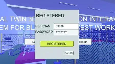
For the virtual twin environment, the interactive interface was designed by GUI, UGUI, and other tools, the control script was designed by C# language, and the interactive function response was realized by the external mouse, keyboard and other devices. The system login and registration function interface is shown in Fig.11.
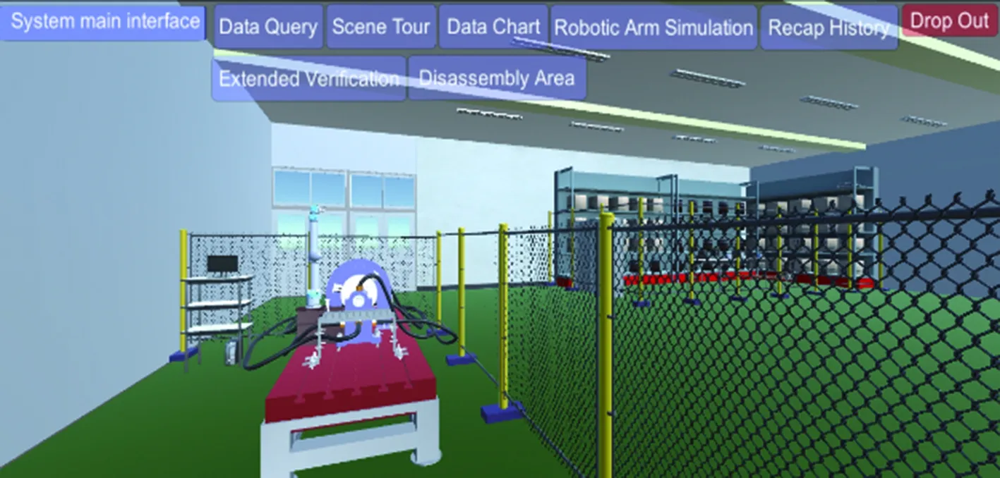
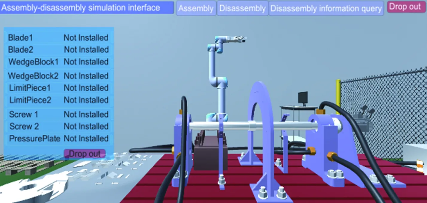
In the digital twin system, the select interactive functions on the main interface of the system are shown in Fig.12(a). The assembly-disassembly simulation interface is
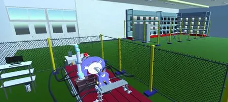
Fig.10 Virtual environment of the blade rotor test workshop
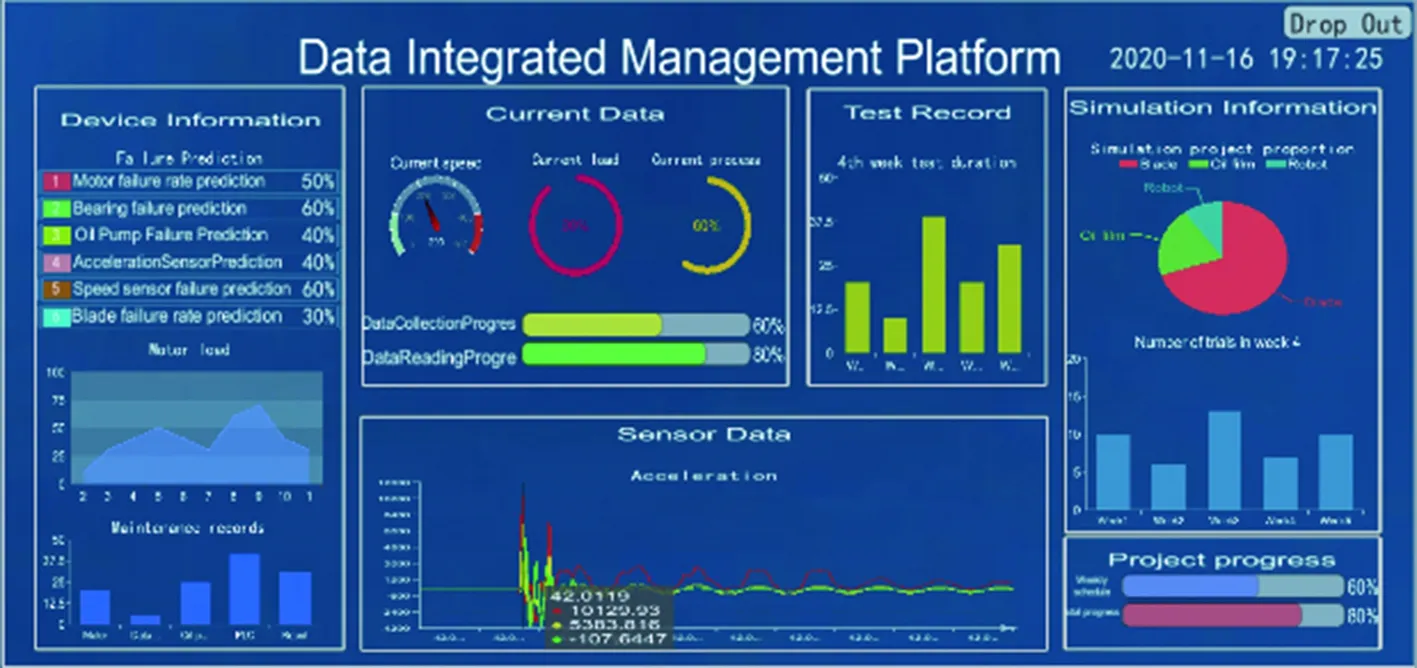
shown in Fig.12(b), which provides a demonstration and training of the disassembly and assembly of the test equipment. The virtual simulation interface of the robotic arm is shown in Fig.12(c). The user can control the robotic arm through the mouse and keyboard. The Matlab mechanical arm simulation function was called to complete the blade assembly path planning. The data chart interface is shown in Fig.12(d), which provides bar charts, pie charts, and line charts to view the entire system and operating data of each device, including speed, blade frequency, running time, test progress, simulation progress, etc.

Fig.11 System login and registration function interface
(a) (b)

(c) (d)
The interactive function has been designed for the system’s human-computer interaction. The system login and registration human-computer interaction display are shown in Figs.13(a) and (b).
After they had lived like this for a few years,26 it happened one day that a Prince27 was riding through the wood and passed by the tower. As he drew near it he heard someone singing28 so sweetly that he stood still spell-bound, and listened. It was Rapunzel in her loneliness trying to while away the time by letting her sweet voice ring out into the wood. The Prince longed to see the owner of the voice, but he sought in vain for a door in the tower. He rode home, but he was so haunted by the song he had heard that he returned every day29 to the wood and listened. One day, when he was standing thus behind a tree, he saw the old Witch approach and heard her call out:
The UI interface is clicked to interact with the mouse, and the user name and password are entered on the keyboard to achieve user information and data interaction.
The system scene-roaming human-computer interaction display is shown in Fig.14. The interactive control of the camera has been completed through the cooperation of the mouse and the keyboard, which is convenient for the multi-directional and close-range understanding of the device information. The figure provides four perspectives.
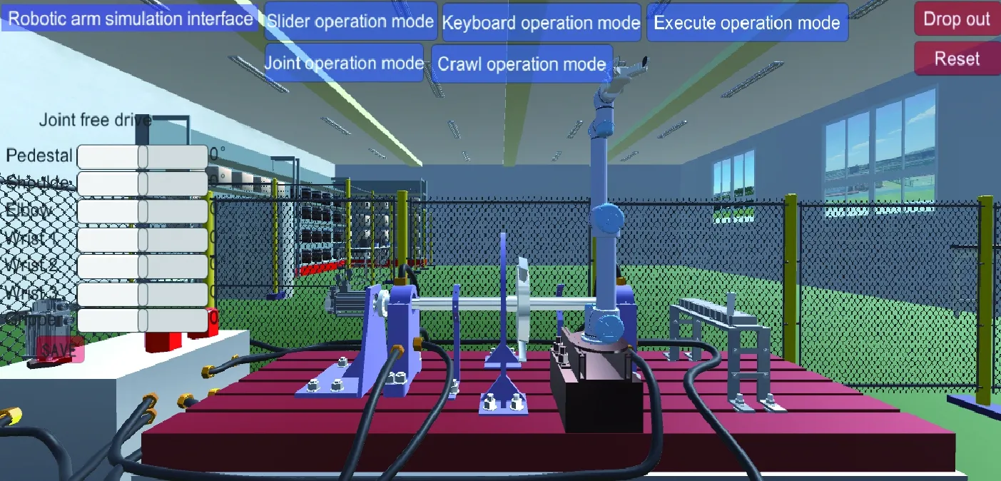
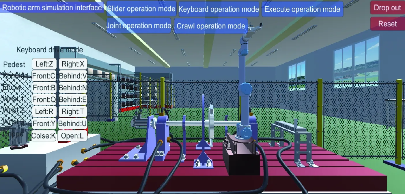
The man-machine interaction display of the systemrobotic arm is shown in Fig.15, which shows two interactive operation modes of the sliding bar and keyboard input.
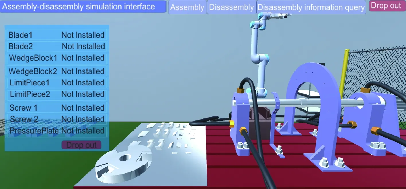
The human-computer interaction display of system assembly and disassembly is shown in Fig.16. During the

(a)
(b)

(a)

(b)
(a)
(b)
(a)

(b)
assembly and disassembly process, the mouse has been used to click and interact with the model. Model judgment, dragging, and posture adjustment have been completed through ray inspection, and information query has been realized through UI interface interaction.
4.3 Realization of real-time data drive and process mapping
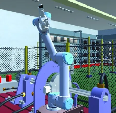
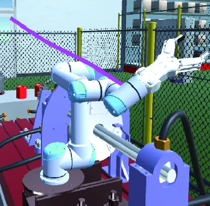
In order to achieve data management for the digital twin system, the input/output ports of the two PLCs of the rotor test bench require definition, and communication with the drive motor, oil pump, data collector, UR5 robot arm, and other equipment has been established through the ports. For example, the UR5 robotic arm in the physical test workshop has been controlled by a program or a teach pendant. Real-time updated control data has been transmitted to the PLC through the input/output IO port, and then uploaded to the UA server through the OPC UA protocol. Data from the UA server node through the program script is read, and the read UR5 motion data in the robot database is stored. The virtual twin environment and the UT read real-time data through the packaged database API interface, and pass them to the parameters of the geometric transformation and physical properties of the 3D model. The synchronous drive of the robotic arm in the virtual environment is shown in Fig.17.

(a)
(b)
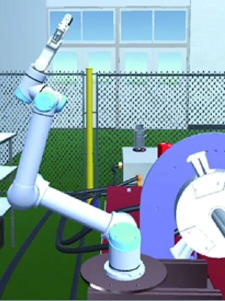
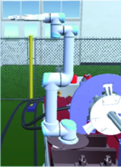
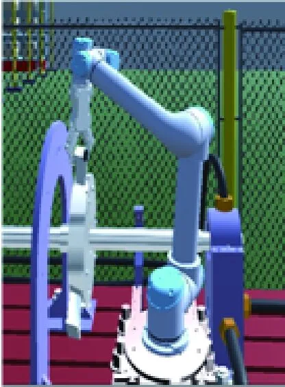
The sequence of the test bench UR5 robotic arm to perform the task of the blade assembly is: 1) Move to the test bench blade storage area; 2) Grasp the blade with the gripper action; 3) Move to the assembly position; 4) Release the gripper. The UR5 robotic arm and the UR5 robotic arm blade assembly drive process the virtual environment by acquiring real-time data of the UR5 robotic arm, as shown in Fig.18.
4.4 Realization of external simulation service creation and application
In terms of system external service, the robotic arm simulation sub-requirements in the system are taken as an example for designing and building simulation sub-services.

(a)

(b)

(c)
(d)

(e)
(f)
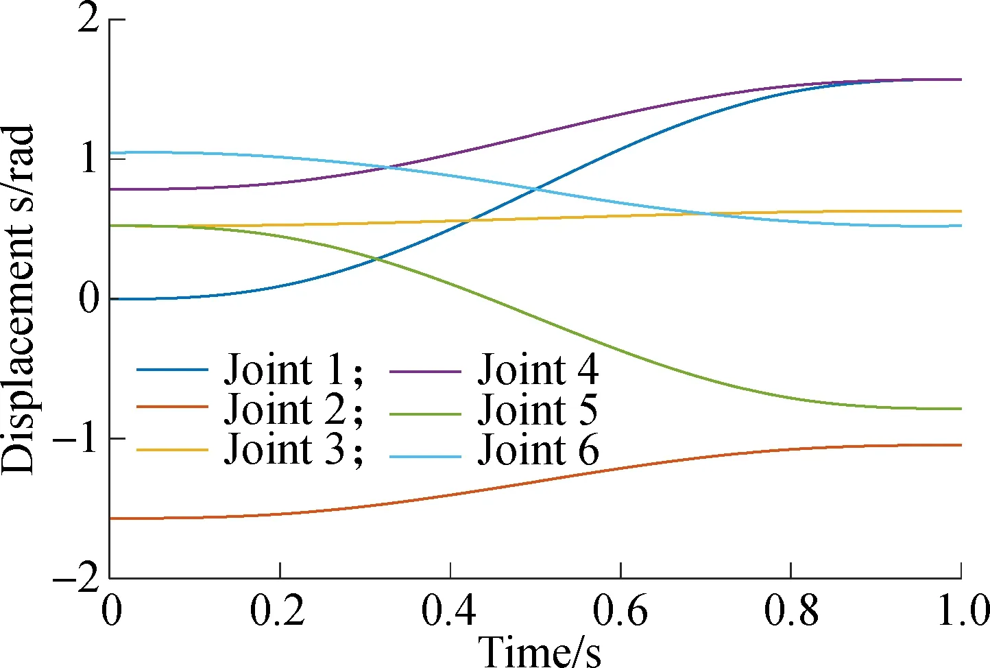
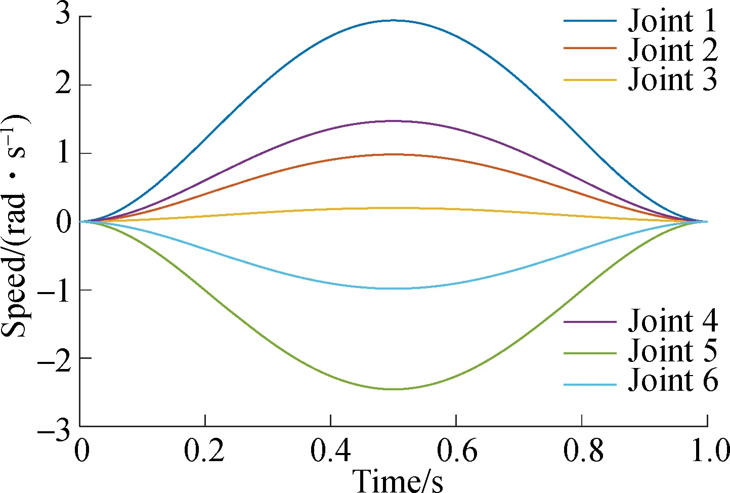
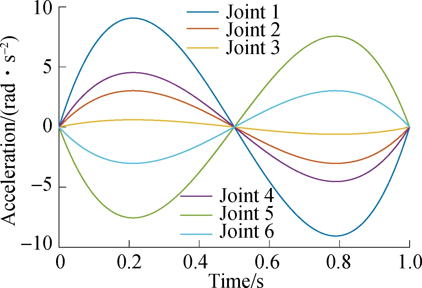
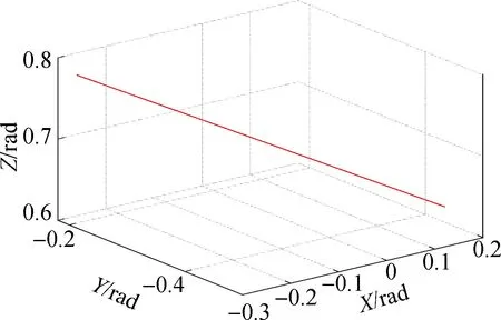
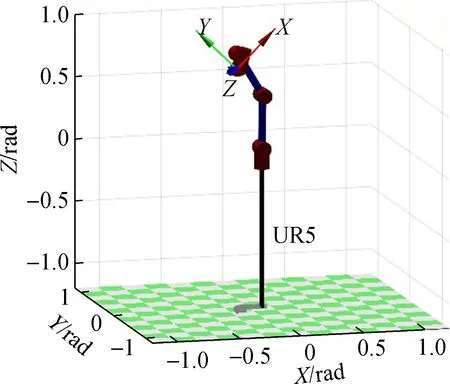
In this paper, MATLAB has been selected as the robotic arm simulation service development software to establish an external robotic arm simulation sub-service. Among them, the Robotic Toolbook for MATLAB in MATLAB is a commonly used robot kinematics solution and simulation tool. This time, the point-to-point joint space and Cartesian space trajectory planning simulation sub-services have been created. In MATLAB Robotics Toolbox, the 3D mathematical model of the UR5 robot was established using the Link function according to the Denavit-Hartenberg (DH) parameter method. The forward and inverse kinematics of the UR5 robot have been solved, and the quintic polynomial interpolation method has been used to determine the motion trajectory of the robotic arm. The initial conditions of the trajectory planning include acceleration, which can ensure the stability of the robotic arm in the joint space. Matlab robotic arm trajectory planning simulation results are shown in Fig.19.
The man-machine interaction design of the robotic arm trajectory planning simulation has been carried out in the virtual environment. By receiving MATLAB data, the byte data has been converted into string data at the same time. The data has been transferred to the robotic arm model parameters. The simulation results of the robot trajectory planning in the virtual environment is shown in Fig.20.
(a)
(b)
(c)
(d)
(e)

(f)
In the virtual environment, the man-machine interaction design of the simulation data feedback control of the robotic arm trajectory planning was carried out. The data feedback and control have been completed by establishing communication with the physical test bench robotic arm. The physical environment robotic arm trajectory planning operation result is shown in Fig.21.
(a)
(b)

(a)
(b)
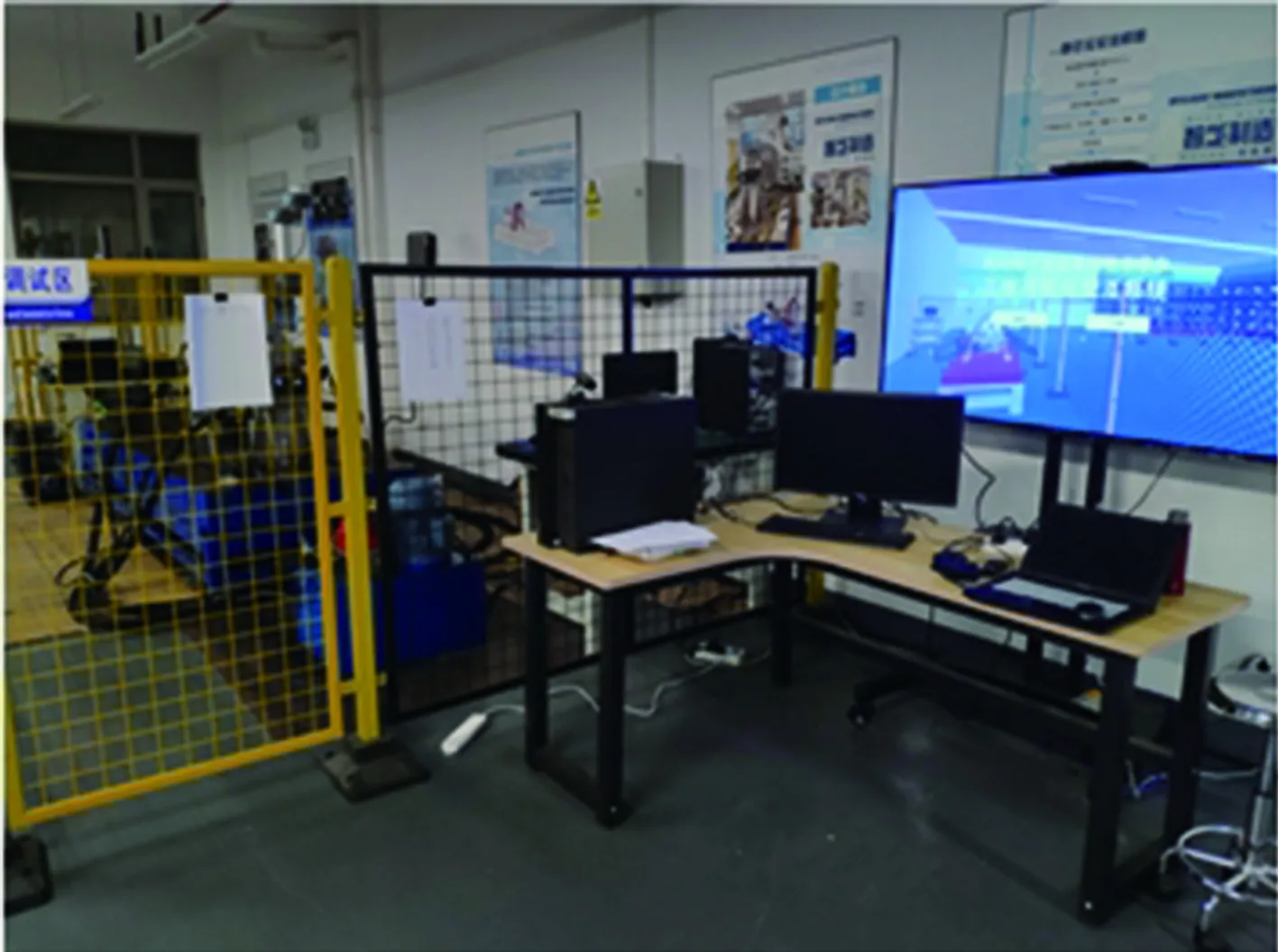
4.5 Client terminal application
The user terminal of the system has been applied to the physical blade rotor test workshop. The running scene of the client terminal is shown in Fig.22.
(a)
(b)
5 Conclusions
1) A novel six-dimensional model of a three-dimensional visualization interactive system for digital twin workshops has been proposed in this paper. The application of the system shows that the model improves the coordination and integration of human-object-virtual in the digital twin workshop, and enhances the importance of personnel in the digital twin workshop.
2) A hierarchical real-time data-driven mapping model for the workshop production process has been proposed in this paper. The application shows that the data-driven and mapping efficiency of the model is higher, the data-driven process is clearer, the data-driven real-time performance is better, and the data feedback control of the physical workshop can be realized.
3) Based on the six-dimensional model of the system, the creation of a three-dimensional visualization virtual environment based on virtual reality has been researched and realized. At the same time, the construction of a data management cloud platform is completed, and research and creation of external services are conducted. The integrated development and application of the 3D visualization interactive system for the blade and rotor test workshop are completed.
4) This system improves the transparency and automation level of the blade test workshop, and at the same time improves the data analysis ability of the blade test workshop, and provides a simulation environment that is not available in the physical workshop. The optimization and guidance of the physical blade test workshop are realized.
杂志排行

Journal of Southeast University(English Edition)的其它文章
- Effects of crankpin bearing speed and dimension on engine power
- A method for workpiece surface small-defect detection based on CutMix and YOLOv3
- Design and evaluation of cab seat suspension system based on negative stiffness structure
- Transformer-like model with linear attention for speech emotion recognition
- Non-inverting buck-boost DC-DC converter based on constant inductor current control
- No-reference blur assessment method based on gradient and saliency