Performance evaluation of the incorporation of different wire meshes in between perforated current collectors and membrane electrode assembly on the Passive Direct methanol fuel cell
2021-06-26MuralikrishnaBoniSrinivasaRaoNagaSrinivasulu
Muralikrishna Boni,S.Srinivasa Rao,G.Naga Srinivasulu
Department of Mechanical Engineering,National Institute of Technology Warangal,Warangal,Telangana,India
Keywords:Passive DMFC Perforated current collector Wire mesh current collector Methanol concentration Fuel cell performance
ABSTRACT Passive Direct methanol fuel cells (DMFC) are more suitable for charging small capacity electronic devices.In passive DMFC,the fuel and oxidant are supplied by diffusion and natural convection process on the anode and cathode sides respectively.Current collectors (CC) play a vital importance in fuel cell performance.This paper presents the combined impact of perforated and wire mesh current collectors(WMCC) on passive DMFC performance.Three types of open ratios of perforated current collectors(PCC),such as 45.40%,55.40%and 63.40%and two types of wire mesh current collectors with open ratios of 38.70% and 45.40% were chosen for the experimental work.A combination of Taguchi-L9 rule is considered.A combination of three PCC and two WMCC on both anode and cathode was used.Methanol concentration was varied from 1 mol﹒L-1–5 mol﹒L-1 for nine combinations of PCC and WMCC.From the experimental results,it is noticed that the combination of PCC and WMCC with an open ratio of 55.40% and 38.70% incorporated passive DMFC produced peak power density at 5 mol﹒L-1 of methanol concentration.The passive DMFC performance was evaluated in terms of maximum power density and maximum current density.The combined current collectors of PCC and WMCC open ratios of 55.40%+38.70% have more stable voltage than single PCC of open ratio 63.40% at 4 mol﹒L-1 of methanol concentration.
1.Introduction
Portable electronic devices such as personal data assistants,mobile phones,laptops,computers,and other power operating devices,which play a pivotal role in modern life draw maximum amount of energy[1].The current rechargeable battery technology will not meet the requirements of present demands.In the next few years,when there would be great demand and use of power devices,scarcity of conventional energy sources in future devices demand that fuel cell technology provide feasible solution to meet the present challenges.
Over the past few years’lot of research carried out on DMFC.In passive DMFC,fuel and oxidant takes place by passive condition,i.e.,passive methanol supply and air breathing.While in the conventional passive DMFC system,the diluted methanol solution directly exposed to anode side MEA through current collector(CC).Cathode side MEA is open to the atmosphere for air breathing via cathode current collector(CCC).In Passive DMFC is very useful for charging small electronic devices which emit no harmful gases other than carbon dioxide.The present study focuses on the combined influence of PCC and WMCC on the performance of a passive DMFC.Here,some literature review regarding WMCC and PCC with the impact of OR is given below.
Falcao et al.[2] experimented the effect of wire meshes with open ratios of 31%,38.7%,44.3%and 51.9%combined with circular open ratio current collector.It was observed that wire mesh with an open ratio of 38.7% on both anode and cathode produced maximum power density of 29.3 mW﹒cm–2.The PCC with the addition of WMCC enhanced current collection and reduced methanol crossover.Shrivastava et al.[3]conducted experiments on five different open ratios of WMCC with ten different open ratios of supporting plate configuration on the performance of a passive DMFC.It was identified that wire mesh with an OR of 41%and supporting plate with an OR of 57.8%combination gave better fuel cell performance compared with single PCC.This was due to the supporting plate enhancing the contact between MEA and CC and also the wire mesh increasing the capillary action of methanol fuel in plane direction as well as,uniform fuel distribution at anode catalyst layer.
Munjewar and Thombre [4] experimented the impact of CC roughness on the performance of a passive DMFC.It was revealed that optimum surface roughness of 0.869 μm yielded better fuel cell performance.The optimum surface roughness decreased contact resistance and increased reactant flow into the catalyst layer.Calabriso et al.[5]experimentally studied the influence of PCC with open ratios of 17%and 35%on the performance of a passive DMFC.It was noticed that 35% open ratio CC gave better fuel cell performance.Braz et al.[6]experimentally investigated the effect of perforated current collector open ratios,i.e.,34%,41% and 64% on the passive DMFC performance.It was observed that lower open ratio of 34% gave better fuel cell performance than other three current collectors.Zhang et al.[7] investigated the influence of incorporation of Tin coated stainless steel wire meshes with five different open ratios of 33.09,44.65,53.58,57.15,and 59.68 between MEA and flow field on the performance of an active DMFC.It was observed that incorporation of 33.09% open ratio wire mesh gave better fuel cell performance compared to other meshes.
Yuan et al.[8] experimentally analysed the circular-hole-array(CHA) current collectors with an OR of 50.24% &28.26% and parallel-fence (PF) current collectors with OR 75.04% &63.49% on the performance of a passive DMFC.It was revealed that CHA with an OR of 50.24% and PF with an OR of 63.49% produced highest MPD.Mallick and Thombre [9] experimentally studied the impact of EMCC on the performance of a passive DMFC.It was noticed that EMCC had more uniform fuel distribution on anode catalyst layer compared to PCC.Boni et al.[10] experimentally investigated the influence of the cathode current collectors,such as WMCC,WMCC with supporting plate and PCC on the performance of an airbreathing DMFC.It was identified that,out of the three current collectors,wire mesh with supporting plated produced higher power density.Wang et al.[11]expanded metal mesh with smaller strand widths gave better passive DMFC performance at lower methanol concentrations and worse at higher methanol concentrations than conventional perforated current collectors.Hen et al.[12]From the experimental results,it was observed that vertical parallel fence(S1)and composite structure(S3)gave better fuel cell performance at lower and higher methanol concentrations respectively.In composite structure,CO2resists methanol crossover (MCO) at concentrated solutions (i.e.,8 mol﹒L-1) and at diluted solutions,CO2was quickly removed from reaction sites.
Scott et al.[13]experimentally examined stainless steel meshes for the evacuation of CO2bubbles on the anode side of passive DMFC.It was also identified that thick mesh with low voidage and a rough surface gave better fuel cell performance.Yuan et al.[14] compared the results of Au coating on Aluminium CC with graphite flow fields on the performance of an air breathing DMFC.It was revealed that Au-coated aluminium current collector had higher water contact angle,lower electrical resistance and weight.Au-coated aluminium current collector incorporated fuel cell produced higher peak power density compared to graphite flow fields,which was 19.8 mW﹒cm–2.Yousefi et al.[15] experimentally studied the impact of silicon rubber gasket location and methanol concentration on the performance of a passive DMFC.It was noticed that silicon rubber gaskets placed between methanol reservoir and anode CC and between MEA and anode CC led to better cell performance.Yousefi et al.[16]experimented the effects of relative humidity,environmental temperature and cell orientation.It was observed that low relative humidity and higher temperature produced maximum power densities and vertical oriental of the cell gave better performance.Borello et al.[17]conducted experiments that analysed the effect of current collectors with open ratios of 36% and 38% on passive DMFC performance.It was identified that higher OR of CC had higher fuel cell performance in methanol concentration range from 1 mol﹒L-1-3 mol﹒L-1.Xue et al.[18] presented the impact of circular hole sizes of cathode current collector with constant open ratio on passive DMFC performance.It was observed that small uniformly sized holes on cathode side provided better water removal and oxygen transfer to reaction sites.
Mallick et al.[19]analysed clamping bolt torque effects on passive DMFC performance.It was observed that 5 to 8 Nm torque increased the fuel cell performance and there after which it decreased the cell performance.This was due to ohmic and mass transfer resistances which decreased up to 8 Nm bolt torque.Chen and Zhao [20] investigated metal porous current collectors effect on the cathode side of a passive DMFC.It was identified that porous current collectors enhanced oxygen diffusion rate,cell temperature and water removal rate compared to perforated current collectors.M.boni et al.[21] experimentally studied the effect of Liquid Electrolyte (LE) layer thickness,i.e.,1.5 mm,2 mm and 2.5 mm on the performance of a passive DMFC.It was identified that,out of the three thicknesses 2 mm thickness LE layer better fuel cell performance compared to without LE layer fuel cell.Qijun et al.[22]experimentally analysed the effect of sulfonated poly(ether ketone) (SPEEK) membrane with the addition of silica powder on performance of a DMFC.It was revealed that addition of silica powder to SPEEK increased proton conductivity,dimensional stability and high proton conductivity at higher temperatures.Min et al.[23] Electrochemical Impedance Spectroscopy (EIS) studies were conducted on the DMFC by measuring the ohmic resistance.It was noticed that ohmic resistance decreases with increase in current density.
Thus,from the literature,most of the research work focused on the influence of open ratios of perforated and wire mesh current collectors.Some works were related to a combination of different open ratios of wire meshes with single circular open ratio current collector.The current research work presents an experimental study of the combined effect of three types of open ratios of circular perforated current collector (PCC) (45.40%,55.40% and 63.05%)and two types of open ratios of wire mesh current collectors(WCC)(45.40% and 38.70%).
2.Experimental
2.1.Passive DMFC components
The main components of the passive DMFC are current collectors on both anode and cathode side,Membrane Electrode Assembly (MEA),gaskets,end plates for anode and cathode side.A detailed explanation of each component is given below (Table 1).

Table 1 Different types of MEAs
2.1.1.Current collectors
The anode and cathode side current collectors are attached to gas diffusion layers.These are used to collect electrons on the anode and cathode catalyst layers.In passive DMFC,open area type current collectors are used for allowing the fuel at anode side and oxidant at cathode side.In the experimental work,two types of current collectors were used:PCC with open ratios of 45.40%,55.40% and 63.40% and WMCC with open ratios of 38.70% and 45.40%,which are shown in Fig.1 (a)-(b).

Fig.1.Passive DMFC components.
2.1.2.Membrane Electrode Assembly (MEA)
MEA is the main component of the fuel cell.It is composed of gas diffusion layers,catalyst layers and membrane.Anode and cathode gas diffusion layers are fabricated with carbon cloth,which allows the fuel and oxidant on anode and cathode side respectively.Anode catalyst layers are made of 60% Pt-Ru/black+Pt-Ru/C with a loading of 2.5 mg﹒cm–2and 1.5 mg﹒cm–2respectively.Cathode catalyst layer is coated with 60% Pt-Ru/C with a loading of 4 mg﹒cm–2and Nafion 117 membrane within an active area of 25 cm2is used.The complete assembly of MEA is shown in Fig.1 (c).
2.1.3.End plates
Two end plates on the anode and cathode side are made of Poly methyl methacrylate (PMMA).The anode end plate acts as a methanol reservoir while supporting the assembly and it has two holes on top of the plate.One hole is for filling of dilute methanol solution and the other one is for removal of CO2from methanol reservoir.Cathode end plate is used for supporting the assembly.Thicknesses of end plates are 18 mm and 8 mm on the anode and cathode side respectively,demonstrated in Fig.1 (d)-(e).
2.1.4.Gaskets
Teflon gaskets with thickness of 0.23 mm were used in this experimental work,which are placed in between MEA and current collectors on both sides of the fuel cell.This arrested liquid leakage on anode side and also decreased the pressure acting on MEA.The gasket is shown in Fig.1 (f).
2.2.Cell assembly
The main parts of passive DMFC consists of a methanol reservoir,which has two holes of 3 mm diameter each for inlet of fuel and CO2outlet,anode and cathode current collectors followed by MEA,Teflon gaskets,PMMA cathode end plate.A PTFE gasket of 0.23 mm thickness is placed between current collector and the MEA.A Combination of current collectors is used on both sides of the fuel cell.The total parts of a cell are assembled using nuts and bolts with an applied torque of 5 Nm.The exploded view of a passive DMFC is shown in Fig.2,and the combination of current collectors placed over methanol reservoir is demonstrated in Fig.3.
2.3.Experimental set-up and test conditions
DC electronic load bank was used to record the Current–Voltage data.For recording,each voltage at a time lap of one minute was considered between two consecutives for achieving stable voltage.Before starting the experiment,a new MEA was activated for 12 h of duration at 1 mol﹒L-1of methanol concentration.All the experiments were conducted at 27–28°C and 60%relative humidity.The experimental setup of passive DMFC is shown in the Fig.4.For evaluating the durability of the MEA and fuel cell performance with respect to time duration,the experiments were performed at constant current density of 25 mA﹒cm–2and six hours’ time duration.

Fig.2.Exploded view of the passive DMFC [21].1—Anode methanol reservoir;2—Anode current collector;3—Teflon gasket on the anode side;4—MEA;5—Teflon gasket on the cathode side;6—Cathode current collector;7—Cathode end plate with opening for air breathing.

Fig.3.Combination wire mesh current collector with perforated current collector.

Fig.4.Experimental set up of the passive DMFC.

Fig.5.Effect of anode catalyst supports for M1 type current collector.
3.Results and Discussion
Experiments were conducted to evaluate the impact of the combined wire mesh and perforated current collectors on the performance of the passive DMFC.Three different open ratios of PCC were used:45.40%,55.40% and 63.40%.Two different OR of WMCC 45.40% and 38.70% were considered for this experimental work.A total of nine combinations of combined current collectors were made using the three PCCs and the two WMCCs,as shown in Table 2.For each assembly of the combined current collector,experiments were performed by varying the methanol concentration from 1 mol﹒L-1–5 mol﹒L-1to identify the optimum combination which gives the best performance.Experiments were also conducted to evaluate the long-term operation of the passiveDMFC.The results of all these experiments are discussed in the following sections.

Table 2 Different open ratio combinations of the perforated current collector with a wire mesh current collector
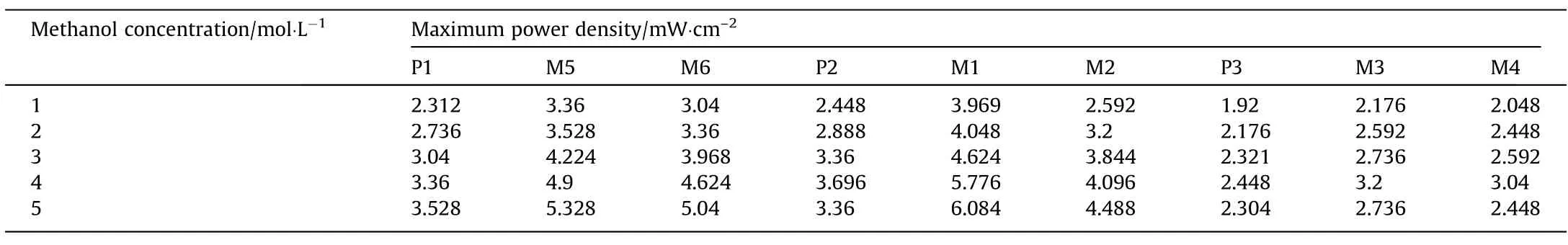
Table 3 Maximum power density values for nine combinations of current collectors

Table 4 Percentage increase in maximum power density for nine combination of current collectors
3.1.Effect of combined catalyst supports on anode side
Fig.5 shows the polarisation characteristic curves of passive DMFC with incorporation of MEA-1 and MEA-2.The fuel cell performances were compared at methanol concentration of 3 mol﹒L-1.In MEA-1,only one layer of Pt-Ru/C anode catalyst was used,while MEA-2 based catalyst had two layers of catalysts i.e.,Pt-Ru/black as inner layer and Pt-Ru/c as outer layer.It can be seen from the Fig.5 Pt-Ru/black+Pt-Ru/C (MEA-2) catalyst coated fuel cell showed higher fuel cell performance compared with conventional Pt-Ru/C catalyst coated fuel cell.This is due to the electrochemical surface activity of Pt-Ru/black being higher than that of Pt-Ru/C catalyst.

Fig.6.(a)-(e) Performance comparison of the different combinations of the wire mesh with perforated current collectors.
3.2.Effect of combination of current collectors (perforated and wire mesh)
Fig.6 depicts the polarisation and power density curves of the passive DMFC fitted with different nine combinations of the WMCC and PCC and varied the methanol concentration from 1 mol﹒L-1–5 mol﹒L-1.It can be observed from the Fig.6 that among the nine combinations,the fuel cell with M1 type combination of CC gave the best fuel cell performance,and the P3 type PCC fitted fuel cell gave the lowest performance compared to the fuel cells fitted with the other combinations of current collectors.The M1 type combined current collector was made of a combination of PCC with 55.40% OR and WMCC with 38.70% OR while the P3 type current collector was a PCC having OR of 63.40%.The fuel cell fitted with current collectors of M5,M6 are gave higher performance than P1.Similarly,M1 and M2 show maximum fuel cell performance than P1.In P3 combination,M3 and M4 gave higher fuel cell performance than P3.
From the Fig.6,it can be noticed from the figures that at any methanol concentration the effect of adding the wire mesh current collector is to increase the MCD,MPD and the operating voltage of the cell compared to the base configuration of only PCC.The current density corresponding to the MPD is increasing means the chemical reaction rate is increasing.This indicates that more amount of methanol is reaching the catalyst layers and more oxidation is taking place.It may be noted that the difference between the ideal voltage and the actual voltage of the cell is a measure of the losses in the cell.From the figures,it is seen that the operating voltage of the wire mesh incorporated cell is always greater than the basic configuration of only PCC.This indicates that the losses are decreasing with the incorporation of the WMCC for every PCC,and for every methanol concentration.Similarly,it can also be observed that the operating range of the cell is getting widened with the incorporation of the WMCC for every basic PCC configuration and at every methanol concentration.
The reason for this behaviour can be explained as follows.In the combined current collector configuration,the perforated current collector acts as a supporting plate for the wire mesh current collector.This supporting plate helps in providing better contact of the wire mesh current collector with the diffusion layer,thereby reducing the electrical contact resistance.Simultaneously,the incorporation of the WMCC increases the resistance to methanol crossover and thereby reduces the methanol crossover losses.Initially,on the anode side the diluted methanol fuel enters the PCC(having large openings),which allows more amount of fuel to flow.In the second stage,this fuel passes through the wire mesh current collector.At this junction,some amount of fuel is restricted,while the remainder of the fuel reaches to the catalyst reaction sites.It creates a lower methanol concentration gradient between the anode and cathode compartments.Thus,the reduced open ratio of the wire mesh current collector decreases the methanol crossover and enhances the fuel cell performance.
In the case of perforated current collectors,it can be seen from the construction that a large patch of solid material lies in between two openings.There will be no reactant flow through this solid patch.This reduces the effective reaction area of the membrane.On the other hand,in the case of WMCC,the WMCC is made of thin wires of small diameter.Thus,in between two openings of the WMCC,a smaller patch of solid space,equal to the diameter of the mesh wire only exists.This helps in not only improving the flow of the reactants but also makes it more uniform.The effective reaction area considerably increases,even though the Open ratio is small for the WMCC.This produces more uniform distribution of fuel on the catalyst reaction sites with WMCC compared to the PCC.Thus,the PCC and WMCC combination provides more uniform distribution of the reactants at the catalyst layers and at the same time the current carrying capacity is not diminished.Thus,the incorporation of the WMCC aids in improving the performance of the fuel cell.The increasing order of fuel cell performance with incorporation of nine combination current collectors is P3,M4,M3,P1,P2,M2,M6,M5 and M1.
It can be seen from the Table 3 that for the P1 type current collector there is a monotonous enhancement in the power density with increase in the methanol concentration,but the rate of enhancement is less at higher methanol concentration.But,for the P2 and P3 current collectors,there is no monotonous enhancement in the MPD increase with increase in the methanol concentration,i.e.,the MPD initially increases with increase in the methanol concentration,reaches a maximum,and then decreases with further increase in the methanol concentration.The MPD is obtained at 4 mol﹒L-1methanol concentration.
On the other hand,it can also be observed from the table that for the M1 and M2 combinations associated with the P2 current collector (OR 55.40%),and for the M5 and M6 combinations associated with the P1 current collector(OR 45.40%)there is a monotonous enhancement in the MPD with increase in the methanol concentration from 1 mol﹒L-1to 5 mol﹒L-1,whereas for the M3 and M4 combinations associated with P3 current collector,there is no monotonous enhancement of the MPD with increase in the methanol concentration.For these M3 and M4 combinations the MPD is obtained at 4 M methanol concentration.
It can be observed from the Table 4,that at any methanol concentration M3 is better than M4,M1 is better than M2 and,M5 is better than M6 in terms of the performance.It can be observed that in all these three combinations,i.e.,M5,M1 and M3 combinations,the WMCC is having an open ratio of (38.70%),and in the M6,M2 and M4 combinations,the WMCC is having an open ratio of(45.40%).This indicates that in between WMCC 1 (OR of 38.70%)and WMCC 2 (OR of 45.40%),WMCC 1,which is having smaller OR is giving better performance.
Figs.7,8 and 9 depict the variation of current density at MPD,maximum current density of the cell and the MPD with respect to methanol concentration.The methanol concentration is varied from 1 mol﹒L-1–5 mol﹒L-1for the nine combinations of current collectors.From Fig.7,it is noticed that the current density at the MPD is increasing with increase in the methanol concentration for M1,M5,M6 and M2 type current collector fitted fuel cells,whereas for the other five combinations fitted fuel cell this current density at the MPD doesn’t monotonously increase with increase in the methanol concentration.From Figs.8 and 9,it is observed that the MCD and MPD increase with increase in methanol concentration from 1 mol﹒L-1–5 mol﹒L-1for the M1,M5,M6,M2 and P1 combinations.For the P3,M4 and M3 combination current collectors,the maximum current densities and maximum power densities initially increase with increase in the methanol concentration from 1 mol﹒L-1–4 mol﹒L-1,and then decrease with further increase in the methanol concentration to 5 mol﹒L-1.Only for the P2 type current collector,the cell performance increases from 1 mol﹒L-1–3 mol﹒L-1and then decreases.Among the nine combinations of current collectors,the M1 type combination current collector fitted fuel cell produced the MCD and MPD at 5 mol﹒L-1methanol concentration.The MCD and MPD produced by the M1 incorporated fuel cell are 59.2 mA﹒cm–2and 6.084 mW﹒cm–2respectively,at 5 mol﹒L-1of methanol concentration.The P3 type current collector incorporated fuel cell produced the lowest MCD and MPD,which are 32.8 mA﹒cm–2and 2.304 mW﹒cm–2respectively,at 5 mol﹒L-1of methanol concentration.
It can be seen from the Figs.7–9 that among the nine combinations,M1 gives the best performance at all the methanol concentrations.In the decreasing order of performance are M1,M5,M6 and M2 combinations either in terms of the MPD or MCD or the current density at the MPD.The performance of the other five combinations is far inferior to these four combinations.Added to that,it can also be observed that there is a monotonous increase in the performance with increase in the methanol concentration for these four combinations.

Fig.7.Variation of current density at the MPD with respect to methanol concentration.

Fig.8.Maximum current densities of the passive DMFC with different combinations of WMCC and PCC.

Fig.9.Maximum peak power densities of the passive DMFC with different combinations of WMCC and PCC.

Fig.10.Comparison of WMCC with PCC and only PCC on long-term operation.
It can be noticed from Table 3 that performance of the fuel cell doesn’t improve much with WMCCs also when the PCC was having an OR of 63.05%.The smallest improvement at any methanol was concentration was observed for M4 followed by M3 type current collectors associated with the P3 type PCC.At each methanol concentration,the lowest order of performance was P3 followed by M4 and M3 type current collector fitted cells.This is because of the large opening ratio of the PCC.That indicates that even with wire mesh combined current collectors also the OR of the PCC has a major impact on the performance of the DMFC.
3.3.Long-term operation of wire mesh with perforated and only perforated current collector
Experiments were conducted to evaluate the long-term performance of the fuel cell.Experiments were conducted continuously for a period of six hours for the M1 and P3 combinations of the current collectors at 4 mol﹒L-1of methanol concentration and at a constant current density of 25 mA﹒cm–2.The voltage-time characteristics are depicted in Fig.10.It can be seen from the figure,the M1 type collector gives better stable output voltage compared to the P3 type current collector.This is because the methanol crossover losses are more predominant in the single perforated current collector of P3.These losses increase the cathode over potential.More voltage drop occurred for the fuel cell with P3 type CC compared to the M1 type CC.Because of the methanol crossover,oxygen availability on the cathode reaction sites decreases and the performance deteriorates.
4.Conclusions
The present work experimentally studied the effect of the combined perforated and wire mesh current collectors at different methanol concentrations(1 mol﹒L-1–5 mol﹒L-1).Experiments were also carried out to evaluate the long-term stability of the fuel cell fitted with M1 and P3 current collectors.The following major conclusions are drawn from the experimental results:
(1) From the results,it is observed that Pt-Ru/black+Pt-Ru/C catalyst coated fuel cell has higher cell performance compared with conventional Pt-Ru/C catalyst coated fuel cell.This is due to electrochemical surface activity of Pt-Ru/black being higher than Pt-Ru/C catalyst.
(2) In between the two wire mesh current collectors,the WMCC with 38.70% OR incorporated current collector combination gave better performance with all the three PCCs(of different open ratios).
(3) Among the nine combinations of the current collectors,the M1 type current collector combination incorporated fuel cell exhibited the highest performance and the P3 type current collector incorporated fuel cell gave the lowest performance.The maximum current densities and maximum power densities produced by M1 and P3 are 59.2 mA﹒cm–2,32.8 mA﹒cm–2,6.084 mA﹒cm–2and 2.304 mA﹒cm–2respectively.
(4) Incorporation of wire mesh between perforated current collector and MEA increases current collecting ability and quick disposal of water bubbles at cathode side.
(5) For M1,M5,M6,M2 and P1current collectors,fuel cell performance increases from 1 to 5 mol﹒L-1.And for P3,M4 and M3 current collectors,cell performance increases from 1 to 4 mol﹒L-1and then decreases.Only for P2 type current collector,the cell performance increases from 1 mol﹒L-1-3 mol﹒L-1and then decreases.
(6) For long-term operation,the fuel cell with M1 type combination of the current collector has greater voltage stability compared to the fuel cell with P3 type current collector.
Declaration of Competing Interest
The authors declare no conflict of interest.
Acknowledgements
The authors acknowledged the financial support provided by Department of Science and Technology-Science and Enginering Research Board (DST-SERB),Government of India and Technical Education Quality Improvement-II-Centre of Excellence (TEQIP-IICoE),National Institute of Technology Warangal,India.
杂志排行

Chinese Journal of Chemical Engineering的其它文章
- A comprehensive review of the effect of different kinetic promoters on methane hydrate formation
- An experimental study on the choked flow characteristics of CO2 pipelines in various phases
- Hydrothermal and entropy generation specifications of a hybrid ferronanofluid in microchannel heat sink embedded in CPUs
- Experimental and Numerical Study of Gas-Liquid Flow in a Sectionalized External-Loop Airlift Reactor
- Numerical simulation of heavy fuel oil atomization using a pulsed pressure-swirl injector
- Experimental research on steady-state operation characteristics of gas–solid flow in a 15.5 m dual circulating fluidized bed system