An experimental study on the choked flow characteristics of CO2 pipelines in various phases
2021-06-26YuxingLiShuaiweiGuDatongZhangQihuiHuLinTengCailinWang
Yuxing Li ,Shuaiwei Gu ,Datong Zhang ,Qihui Hu ,Lin Teng ,Cailin Wang
1 Shandong Provincial Key Laboratory of Oil &Gas Storage and Transportation Security,China University of Petroleum (East China),Qingdao 266555,China
2 Department of Energy and Power Engineering,Tsinghua University,Beijing 100084,China
Keywords:CO2 pipeline Steady choked flow Transient choked flow Water Temperature drop
ABSTRACT High pressure pipeline transportation has been an established technology for economically transporting large amounts of CO2.However,there are still issues and associated risks that have to be effectively addressed and adequately understood.It is well known that a strong Joule-Thomson Cooling effect can occur when pressurized CO2 flows through a choke valve.Thus,to investigate the choking characteristics especially the temperature drop of high pressure CO2,a new laboratory scale experimental setup (total length of 14.85 m and the inner diameter of 15 mm)was constructed.Steady choked flow and transient choked flow tests were carried out respectively for pressurized CO2 in various initial phases.The phase transitions and temperature drop characteristics were then studied following the choked flow and the results show that the phase transitions in steady choked flow differs significantly from that in transient choked flow.For transient choked flow of various initial phases,all the flows downstream would transfer from single phase to gas–liquid two-phase flow.Furthermore,the effect of water on transient choked flow of supercritical CO2 pipeline was investigated,and the phenomena of solid particles deposition was captured which was paramount importance of ensuring the safety operation of CO2 pipelines when throttling by the choke valves.
1.Introduction
It is widely accepted that the significant emissions of greenhouse gases especially the carbon dioxide (CO2) can be the main reason for global warming and climate change [1–3].Following the 2015 United Nations Climate Change Conference held in Paris,France [4],a new global climate agreement has been set out to limit the rise in global temperature to 2 °C compared with preindustrial levels.It is furthermore expected from the future energy outlook that the fossil fuels will remain the dominant energy source for the next 20 years[5].Thus,Carbon Capture and Storage(CCS) has been introduced as one of the most important technologies to reduce CO2emissions to the atmosphere and mitigate the environment impact of fossil fuels [6,7].Generally three components account for this CCS chain including the capture,transportation and storage,respectively.To achieve this,CO2must be transported since few storage sites are located near the capture locations,and it is foreseen that pipeline transportation of CO2will be the most economic approach[8,9]as CCS could be deployed on an industrial scale in the future.However,CCS is still a developing technology which may associates a number of issues concerning safety requiring further study and research[10,11].Thus,ensuring a safe implementation of the CO2transportations and mitigating potential hazards is vitally important.
Potential damages to pipelines caused by the outside forces,such as the mechanic damage,construction,corrosions or material defects are unavoidable [12].Once the CO2pipeline releases,CO2cannot expand to atmospheric pressure instantaneously,which may result in the maintained high mechanical stress levels inside the pipeline [7].Moreover,considerable negative effects and threats could be exerted on the local environment and residents nearby due to the high CO2concentration released from the pressurized pipelines[13].Thus to avoid this,throttling method is generally used when the pressure of CO2pipeline is excessively high in case of those potential damages[14].Once the fluid with CO2content flows through a choke valve or a capillary tubes(also denoted as the choked flow [15]),the rapid depressurization can cause a significant drop in the temperature downstream of choke valve due to the strong Joule-Thomson cooling (JTC) effect of CO2[16,17].Upon the CO2flow being choked,the temperature of pipe wall can be lowered to a large extent[18],and sometimes even to its Ductile-Brittle Transition Temperature(DBTT)[19]in the event of the strong heat transfer between pipe wall and CO2fluid.As a consequence,there will be an almost instantaneously large drop in the fracture toughness which will significantly increase the risk of running brittle fracture.Moreover,the temperature of CO2fluid undergoing a near-adiabatic expansion can be as low as -75 °C which may lead to the formation of solid CO2at any point within the pipeline where the pressure falls below the triple point [20].Thus,central to the safety assessment of pressurized CO2pipelines is the accurate investigation of choked flow characteristics upon CO2fluid flowing through the choke valve,which is vitally crucial for the safety operation.
Investigations of highly choked conditions of high pressure CO2pipeline have long been a subject of study.Teng et al.[21] developed a new multiphase choked flow model based on the assumption of isenthalpic and gas–liquid thermal equilibrium to predict the temperature drop for multiphase mixtures with high CO2content through the choke valve.It indicated that choke valve pressure drop and gas components had a great influence on the JTC effect of CO2.Moreover,the deposition characteristic of solid CO2was predicted in his another work [22] with the Computational Fluid Dynamic (CFD) model by using the modified Lagrangian method.Small Solid particles would accumulate tightly on the pipe wall,which was the major account for pipe blockage in the region of sudden expansion.Besides,Pravin et al.[23]presented a numerical study on an adiabatic helical capillary tube employing homogenous and choked flow conditions of a CO2trans-critical system.A simulation graph was developed based on determined conditions of choked and unchoked flow characterizations which was helpful for the design of helical capillary tube.Zhao et al.[14]developed a choked flow model based on the adiabatic process assumption to calculate the temperature drop of pressurized CO2pipeline containing impurities.The existence of SO2was found especially positive in increasing the downstream temperature which was beneficial for the prevention of frozen hazard.Huang et al.[24]performed CO2choked flow experiments in conditions relevant to carbon capture and sequestration with a 60 cm long stainless steel pipe and an inner diameter of 2.1 mm.It was found that the relatively large pressure drop in choke valves could bring about a substantial temperature change due to the strong Joule-Thomson cooling effect of CO2.And moreover,periodic solid CO2deposition and melting phenomena could occur during the release of high pressure CO2pipelines as well.All these researches done above have been applied for the prediction of temperature drop and made great contribution to the mechanism study of solid deposition and periodic blockage in CO2choked flow.However,the experimental development and performance of choked flow through valves with high CO2content is still limited currently although several models have been put forward.In addition,CO2captured by the three main methods (post-combustion,pre-combustion and oxy-fuel combustion) is not 100% pure[25] and Visser et al.[26] conducted a quantitative assessment analysis for greenhouse gas technologies to investigate the human influence of impurities in a CO2pipeline.The findings attested that the existence of water is unavoidable in CO2pipelines and the water content can be different in various CO2streams.Moreover,even a small amount of water can affect the choked behavior of pressurized CO2pipelines dramatically as the low temperature caused by the rapid cooling is always below the freezing point of water.As such,massive ice can generate downstream the choke valve and then cause the periodic blockage,posing a great threaten to the safety operation of pressurized CO2pipelines.
Thus,to address the safety concerns and fully understand the choked flow in high pressure CO2pipelines,a new laboratoryscale pipeline system was designed in our work which could test the complex flow characteristics of CO2upon throttling.The p-T evolvement and phase transitions were investigated in steady and transient CO2choked flow with various initial phase states,respectively.Water was added as the primary impurity in order to study the flow characteristics of CO2-H2O mixture choked flow and determine the mechanism of solid particle deposition during the choked flow.In the following,a brief introduction of the novel experimental setup is firstly presented,followed by experimental results and their discussions.Finally,some conclusions from the study are drawn.
2.Experimental
2.1.Experimental setup

Fig.1.The scene graph of experimental apparatus.
To investigate the characteristics of pressurized CO2choked flow upon flowing through the choke valve,throttling experiments on CO2pipelines in various initial phase states were performed based on a recently developed in-house facility (as shown in Fig.1) and the detailed device setup is illustrated in Fig.2.The apparatus consisted of two main parts:CO2supply system and throttling test system.The CO2supply system includes the CO2gas cylinder,refrigeration box,booster pump and high-pressure buffer tank.The gaseous CO2(with an initial pressure at around 5 MPa and a purity of 99.99%) from the gas cylinder was cooled down to liquid phase in the refrigeration box and then conditioned to high pressure via a booster pump.In the initial stage,pressurized CO2was first stored in the high-pressure buffer tank and then injected into the main pipeline.After the downstream(at the right of choke valve)injected CO2balanced at the expected pressure,the choke valve was closed and booster pump was activated again to pump additional CO2into main pipeline until the set upstream(at the left of choke valve) pressure was reached.The choked flow test section contains the main pipe,choke valve,visible window and the back valve,respectively.The main pipe was made of a 304 stainless steel and was 14.85 m long with an internal diameter of 15 mm,a pipe wall thickness of 3 mm and a maximum operating pressure of 16 MPa.Besides,the main pipe was thermally insulated with a rock wool layer and the heating system consisted of a heating band wrapped around the pipe to control the temperature of CO2for the expectant phase.In the experiments,seven low frequency pressure and temperature sensors with a frequency response of 1 Hz were mounted at seven different positions (one was located upstream while the others were located downstream)along the main pipeline to measure the flow parameters of CO2inside the pipeline.The measurement accuracy of pressure sensors was limited under ±0.25% while the uncertainty of temperature measurements was ±0.5% (temperature was recorded in °C).All data was recorded by the data acquisition system (NI cRIO-9025,a data acquisition card) with LabVIEW software which was used to transfer the data from the acquisition system to a local computer.
2.2.Experimental procedures and uncertainty
The experimental conditions for pure CO2and CO2-H2O mixture throttling tests are listed in Table 1 and Table 2,respectively.Pressure–temperature evolvements and phase transitions in CO2choked flow were investigated for pressurized CO2pipelines in various initial phase states.To evaluate the effect of H2O on CO2choked flow characteristics,the 4%(mol)H2O was added(for brevity only supercritical CO2was considered).A brief experimental procedure for these throttling tests performed was executed as follows:

Table 1 Experimental conditions of pure CO2 throttling tests
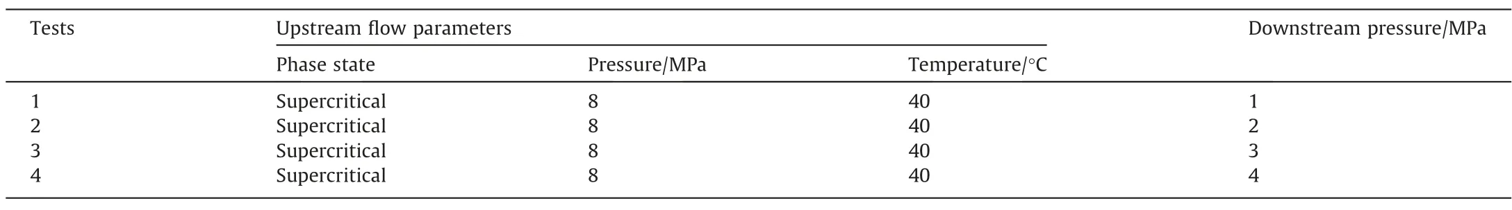
Table 2 Experimental conditions of CO2-H2O mixture transient choked flow
(1) The physical integrity of the whole experimental setup was checked especially the measurement sensors and the leakage nozzle;and the data acquisition system was sure in good condition.
(2) The pipeline was purged by gaseous CO2to evacuate the air in pipeline in order to eliminate impurities.
(3) Pressurized CO2was stored in the buffer tank first and then injected into the main pipe until the appropriate CO2mass had been added into the whole pipe.After then,the choke valve was closed and more CO2mass was added into the upstream pipe to get the expected upstream pressure.
(4) When the set initial pressure and temperature were stabilized,choke valve was opened gradually (remotely by the pneumatic valve).When the downstream temperature dropped to the minimum temperature in the steady choked flow stage,the injection valve was closed while the choke valve was fully opened to make the choked flow taking place transiently.
(5) During the overall choked flow,pressure and temperature were measured at each sensor and recorded by the data acquisition system.
All the tests were stopped when pressure in the pipe decreased to 0.1 MPa.Each test was repeated over more than 3 times in order to improve the reliability of the experimental data and eliminate the influence of acquisition error as much as possible (The total measurement error is within 1%).The maximum uncertainty of pressure measurement in experimental conditions is ±20 kPa and the maximum uncertainty of temperature measurement is ±1 °C.
3.Results and Discussion
3.1.Pressure and temperature responses in CO2 choked flow

Fig.2.Detailed device setup.

Fig.3.Downstream flow parameters profiles of experimental test 2.
Due to the strong Joule-Thomson cooling(JTC)effect of CO2,the temperature inside the pipeline can vary significantly once the CO2flow is choked [27].Thus,to investigate this temperature drop characteristic in CO2choked flow,Fig.3 displays the flow parameter profiles measured downstream by sensor p6 and T6 in throttling test 2.The initial upstream pressure and initial temperature were 5 MPa and 30 °C,respectively,while the downstream pressure was 2 MPa.It can be clearly seen that the throttling test was divided into three stages by two dashed lines.In the first stage,the choke valve was closed initially and the CO2inside the pipeline(both upstream and downstream) was stabilized at the expected pressure and temperature.Subsequently,the choke valve was opened slowly,leading to the steady choked flow in the second stage.Obviously,the downstream temperature dropped continuously from 28°C to approx.3°C in approx.600 seconds.At the same time,the pressure fluctuated slightly and then remained stable at the value nearby 2.2 MPa under the control of choke valve and back pressure valve.Upon the downstream temperature dropping to the minima,the choked flow translated from the steady state to a transient stage (which was denoted as stage 3) by fully opening the choke valve and closing the inlet valve immediately.In the beginning of this stage,a simultaneously rapid increasing in downstream pressure was formulated which was mainly caused by the limited release rate of downstream CO2to the atmospheric environment under the control of back pressure valve.Meanwhile,the downstream temperature increased immediately due to the instantaneous decrease in pressure differences between the upstream and downstream fluid,however to a smaller extent compared to that of the pressure variation.

Fig.4.The temperature drop-pressure drop curves in CO2 choked flow with different initial phases.

Fig.5.Typical image of gaseous CO2 transient choked flow at the visible window.

Fig.6.The upstream and downstream p-T curve of gaseous CO2 transient choked flow.
3.2.Effects of initial phase states on the temperature drop in steady choked flow
The temperature drop-pressure drop curves of CO2steady choked flow in various initial phases(supercritical,liquid and gaseous phase respectively) are given in Fig.4.Clearly,the cooling effect of gaseous CO2was much stronger than that of supercritical CO2while liquid CO2has the smallest temperature drop under the same pressure differences.This phenomenon can be mainly explained by the isenthalpic choked flow model proposed in our previous work[21],and the isenthalpic choked flow can be derived from the energy conservation,which is written as:

where H1represents the upstream enthalpy,kJ﹒kg-1;H2is the downstream enthalpy,kJ﹒kg-1;C1is the upstream flow speed,m﹒s-1;C2is the downstream flow speed,m﹒s-1;Q is the unit quantity of heat,kJ﹒kg-1;W is the external work,kJ﹒kg-1;g is the acceleration of gravity,m﹒s-2;ΔZ is the distance,m.
Based on several assumptions (horizontal pipe,adiabatic flow,the upstream and downstream velocities are nearly equivalent and no external work considered),the isenthalpic choked flow can be simplified as:

According to the definition of the enthalpy,Eq.(2) can be rewritten as:

where u represents the internal energy including the internal kinetic energy and internal potential energy,kJ﹒kg-1;pv represents the flow work,kJ﹒kg-1.
It is well known that the flow work will increase with the decrease of pressure inside the pipeline once the CO2pipeline is choked,which then would lead to a decrease in CO2internal energy.For gaseous CO2throttling tests,due to the large intermolecular distance between gaseous CO2molecules,the internal potential energy increases upon flowing through the choked valve while the internal kinetic energy decreases.Moreover,the temperature variation of CO2choked flow is a single-valued function of internal kinetic energy,which thus can be accounted for the large temperature drop.However,the variation of kinetic energy is considered to be similar to the flow work as intermolecular distance of liquid CO2molecules could be neglected during the throttling tests.As a consequence,the temperature drop of liquid CO2choked flow was smaller than that of gaseous CO2.
Furthermore,unexpected results were found in the data analysis by comparing the p-T curves of throttling tests with downstream pressure of 5 and 6 MPa,respectively.It could be clearly seen that the higher the upstream pressure was,the smaller temperature drop could be for gaseous CO2choked flow(with the same pressure drop).This phenomenon was mainly on account of the intermolecular distance between CO2particles that large initial upstream pressure could have smaller intermolecular distance,and thus a larger temperature drop due to the larger variation of internal potential energy as well as the internal kinetic energy.
3.3.Transient CO2 pipeline choked flow with various initial phase states
3.3.1.Transient choked flow of gaseous CO2
The transient choked flow of gaseous CO2observed from the visible window is shown in Fig.5(For brevity,only the experimental tests done with downstream pressure of 6 MPa was discussed here).As is displayed in the typical image,a small amount of liquid CO2formed once the choke valve was fully opened.And due to the small flow velocity at the initial stage which was mainly caused by the small pressure difference between the upstream and downstream flow,the initially gaseous phase flow inside the pipeline transferred into gas–liquid two phase stratified flow gradually.Fig.6 illustrates the upstream (p7,T7) and downstream (p6,T6)p-T variations of the transient choked flow,respectively.The point A was the upstream experimental condition with an initial pressure of 6 MPa while the point B represented the initial downstream pressure (1 MPa).Point C and D were denoted as the stage where the choke valve was fully opened instantaneously,according to which,the region from point A to B and point C to D were taken as the steady choked flow stage.As is shown from the downstream p-T curve,the downstream pressure remained unchanged while the temperature decreased constantly in the steady choked flow,which however,always stayed in the gas phase region.Once the choke valve was fully opened,the downstream pressure shifted rapidly and the flow inside the pipeline transferred from the gas phase to gas–liquid two-phase flow immediately.Subsequently,due to the rapid decreasing in pressure difference between upstream and downstream,the downstream temperature increased significantly which made the gas–liquid two phase flow inside the pipeline returned to gas phase flow again.

Fig.7.Typical images of liquid CO2 transient choked flow at the visible window.
3.3.2.Transient choked flow of liquid CO2
The transient choked flow of liquid phase CO2observed at the visible window is shown in Fig.7.The initial condition of upstream and downstream flow had a pressure of 8 MPa and 2 MPa respectively,with an initial temperature of 25°C for both.It can be clearly seen from the Fig.7 that the visible window was quickly filled with the liquid CO2once the choke valve was fully opened.After then(t=4 s),a turbulent gas–liquid two-phase flow (denoted as wave flow here) formed inside the pipe which was mainly caused by the rapid variation of downstream temperature and pressure.Subsequently (t=7 s),this wave flow gradually transformed into a stable stratified flow as the downstream pressure tends to be equal with the upstream pressure.Moreover,the gasification of liquid CO2could be observed in this stratified flow with a large number of bubbles generating constantly,leading to a decreasing in the content of liquid phase.Meanwhile,the gas phase contains a mass of droplets as well,and the microscopic image captured by a high-speed camera was shown in Fig.8.Clearly,a plentiful of homogeneous droplets moved randomly in the gas phase and the amount of droplets downstream was significantly less than that of upstream.
Fig.9 displays the upstream and downstream p-T variations of the liquid phase CO2transient choked flow,respectively.The whole transient choked flow was divided into 3 stages again with point A and point B representing the initial phase state(upstream pressure of 8 MPa and downstream pressure 2 MPa,respectively).The regions from point A to point B and point C to point D were the steady choked flow of liquid CO2where the downstream pressure fluctuated slightly and remained stable while the temperature decreased constantly until to a minimum value (about -2 °C).Whereas these variation in pressure and temperature,the phase state of the upstream and downstream CO2remained unchanged during the steady choked flow stage.However,once the choke valve was fully opened at point C and D,the upstream and downstream pressures varied dramatically and reached equivalent quickly,which made the downstream flow change from gaseous phase to liquid phase flow immediately.On the contrary,due to the sharp drop in upstream pressure,the flow upstream changed from liquid phase to gaseous phase flow at the same time.In the end of the choked flow,the downstream temperature increased instantly as the pressure difference between the upstream and downstream fluid decreased,which thus made the downstream fluid returned to gaseous phase flow again.

Fig.8.Micro-phenomenon in liquid CO2 choked flow.
3.3.3.Transient choked flow of supercritical CO2

Fig.9.The upstream and downstream p-T curve of liquid CO2 choked flow.

Fig.10.Typical images of supercritical CO2 transient choked flow.

Fig.11.The upstream and downstream p-T curve of supercritical CO2 choked flow.

Fig.12.Typical images of CO2-H2O mixture transient choked flow.

Fig.13.The upstream and downstream p-T curve of CO2-H2O multiphase choked flow.
Fig.10 displays typical image captured at the visible window of supercritical CO2transient choked flow with an initial upstream pressure of 8 MPa and downstream pressure of 2 MPa,respectively.It can be clearly seen that the characteristics of supercritical CO2transient choked flow were basically the same with that of dense phase CO2,both transferring from highly turbulent wave flow to stratified flow upon the sudden opening of choke valve.However,the visible window was not fully filled with liquid phase in the beginning which differed from that of liquid CO2.This can be mainly explained by comparing the upstream and downstream p-T curves of supercritical CO2(shown in Fig.11) and liquid phase CO2(shown in Fig.9) transient choked flow.Once the choke valve was fully opened,the phase of upstream CO2changed from initially supercritical phase to the gaseous phase directly in supercritical CO2transient choked flow while it transferred to liquid phase flow firstly and then changed to gaseous flow finally for liquid CO2.Furthermore,the pressure and temperature variation of downstream CO2were similar to that of liquid CO2,both evolving from the initial gaseous phase to liquid phase and then returning to gaseous phase in the end.However,a longer liquid phase transition was found in supercritical CO2transient choked flow compared with that in gaseous and liquid CO2.
3.4.Transient choked flow of CO2-H2O mixture
The existence of impurity such as water in the CO2pipeline is inevitable and can have a significant influence on the flow characteristics when pressurized CO2pipelines are choked [28].Thus,to investigate this choked flow of CO2mixtures,typical images of CO2-H2O mixture transient choked flow captured at the visible window were displayed in Fig.12.A large amount of liquid CO2containing a mass of solid particles could be observed at the visible window at the initial stage of transient choked flow.At the first second,due to the strong heat transfer between the fluid and environment,only a small number of solid particles deposited at the bottom of pipe with most of which sublimating into liquid and gaseous phase.Subsequently,all the inventory had released to the atmosphere at the time of 25 s,only with a little solid particles remained and melting slowly along with the constant heat transfer between fluid and environment.As a consequence,the solid deposition layer had completely melted at the window until 50 min later.
Fig.13 displays the upstream and downstream p-T variations of CO2-H2O mixture transient choked flow,respectively.Clearly,the measured temperature drop of CO2-H2O multiphase choked flow was slightly lower than that of pure CO2choked flow compared with Fig.11,which was mainly caused by the small amount of water mixed in CO2initially.Moreover,during the overall transient choked flow,the p-T variation of CO2-H2O mixture evolved without overlapping with the solid line,which indicated that the solid particles downstream were all ice particles due to the solidification of water while the CO2only existed in two phases (gaseous and liquid).The existence of solid particles in the choked flow can be a main risk to the safe operation of high pressure CO2pipelines,especially causing periodic blockage of downstream pipe [24,29].Thus,to address this safety concern and fully understand the deposition of ice particles,several CO2-H2O mixture transient choked flow tests with different pressure differences (4,5,6,7 MPa,respectively) were performed to investigate the critical pressure difference at which ice particle could disappear during the CO2-H2O multiphase choked flow.As is clearly illustrated in Fig.14 that solid particles would [1–4] occur once the choke valve was fully opened for pressure differences larger than 5 MPa.However,when the downstream pressure increased to 4 MPa (i.e.pressure difference was 4 MPa),no solid particles were captured at the visible window,instead it was filled with liquid phase.Based on these phenomena at the visible window,it could be speculated that the critical pressure difference was between 4 and 5 MPa at which no ice particles generated during the choked flow of pressurized CO2pipelines containing water.

Fig.14.Typical images of CO2-H2O mixture transient choked flow under different pressure differences.
4.Conclusions
High pressure CO2pipelines are widely considered as a major contributor to CCS development.However,transporting CO2by pressurized pipelines is still a challenge and a choked flow can pose a significant safety risk in itself which is of fundamental importance.Moreover,the relatively high Joule-Thomson expansion cooling effect of CO2,coupled with choked flow,raises concern that choked flow may eventually cause the periodic blockage of downstream pipe.However the detailed characteristics of CO2choked flow are only poorly understood.Given that,a laboratory scale experiment system was developed to examine the choking behavior of CO2pipelines in various initial phase states.Following conclusions can be drawn from this study:
(1) The downstream temperature of CO2can drop rapidly to a minimum value during the steady choked flow while the downstream pressure remained stable.
(2) The cooling effect in gaseous CO2steady choked flow is much stronger than that in supercritical CO2choked flow while the liquid CO2has the lowest.
(3) Transient choked flow behavior of liquid CO2are similar to that of supercritical CO2as both of their downstream flows change from the strongly wave flow to the stratified flow in transient choked flow.Furthermore,the downstream p-T variations can enter into the liquid region in transient choked flows of various initial phase states.
(4) Solid particles can occur in transient choked flow of pressurized CO2pipelines containing water for larger pressure differences between the upstream and downstream flows.The critical pressure difference at which solid particles disappear is approximately at 4–5 MPa.
Declaration of Competing Interest
The authors declare that they have no known competing financial interests or personal relationships that could have appeared to influence the work reported in this paper.
Acknowledgements
The presented work was funded by Key laboratory of oil &gas storage &transportation PetroChina (GDGS-KJZX-2016-JS-379),and supported by the National Science and Technology Special Project (2016ZX05016-002).
杂志排行

Chinese Journal of Chemical Engineering的其它文章
- A comprehensive review of the effect of different kinetic promoters on methane hydrate formation
- Hydrothermal and entropy generation specifications of a hybrid ferronanofluid in microchannel heat sink embedded in CPUs
- Experimental and Numerical Study of Gas-Liquid Flow in a Sectionalized External-Loop Airlift Reactor
- Numerical simulation of heavy fuel oil atomization using a pulsed pressure-swirl injector
- Experimental research on steady-state operation characteristics of gas–solid flow in a 15.5 m dual circulating fluidized bed system
- Thermal performance assessment of self-rotating twisted tapes and Al2O3 nanoparticle in a circular pipe