偏振激光雷达增益比定标方法对比研究
2021-06-15童奕澄童学东戎宇航周雨迪
童奕澄,童学东,张 凯,肖 达,戎宇航,周雨迪,3,刘 崇,刘 东
(1. 浙江大学 光电科学与工程学院 现代光学仪器国家重点实验室,浙江 杭州 310027;2. 宁波钢铁有限公司 浙江 宁波 315807;3. 浙江大学 宁波研究院 浙江 宁波 315100)
1 Introduction
Polarization lidar is one of the earliest members of lidar family. Since its birth in 1971, polarization lidar has become a research tool widely used in atmospheric cloud and aerosol detection[1]. The depolarization ratio obtained by polarization lidar inversion can be used to distinguish spherical and non-spherical particles, so it is often applied to the identification of aerosol type and the identification of thermodynamic phase state of clouds[2].Moreover, the depolarization ratio can also be used to identify the tropospheric boundary layer and to distinguish polar stratospheric clouds from other types of clouds in terms of morphology[3-5]. At the same time, the depolarization ratio can be used to study the long-distance transmission characteristics of dust[6]. It can be seen that the high-precision detection of depolarization ratio is of great significance to atmospheric science research. However,how to improve the detection accuracy of depolarization ratio has always been the research focus of polarization lidar[7].
The main causes for depolarization ratio error include: the calibration error of polarization lidar gain ratio, the error caused by the impurity of laser ray polarization, the alignment angle error between laser polarization vector and Polarization Beam Splitter (PBS) incidence plane, as well as the polarization crosstalk error caused when the reflectance and transmittance of PBS cannot reach 100%. In order to simplify the description, the above four errors are referred to as gain ratio calibration error,linear polarization error, alignment angle error and polarization crosstalk error respectively. Among them, gain ratio calibration error is particularly important and has a decisive effect on the accuracy of depolarization ratio[8]. The gain ratio calibration error varies with the gain ratio calibration method. For nearly half a century, more and more researchers have proposed new gain ratio calibration methods.However, there is still a lack of effective guidance and suggestions on the selection of gain ratio calibration method in the actual use of polarization lidar.
This paper analyzes the basic principles of various existing gain ratio calibration methods and compares the accuracy and advantages and disadvantages of +45° method, +45° method, ∆45° method, rotation fitting method and pseudo-depolarizer method at different misalignment angles through experiments. Through the comparison of theory and experiment, this paper provides a suggestion for the best choice of gain ratio calibration method.
2 Basic principles and structure
The typical polarization lidar is a two-channel lidar[1]. According to the definition of depolarization ratio δ[9], we can obtain
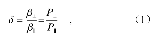
where β represents atmospheric backscattering coefficient,Prepresents the echo signal power, and the subscripts ⊥ and ‖ respectively represent the vertical and parallel components of the above parameters.
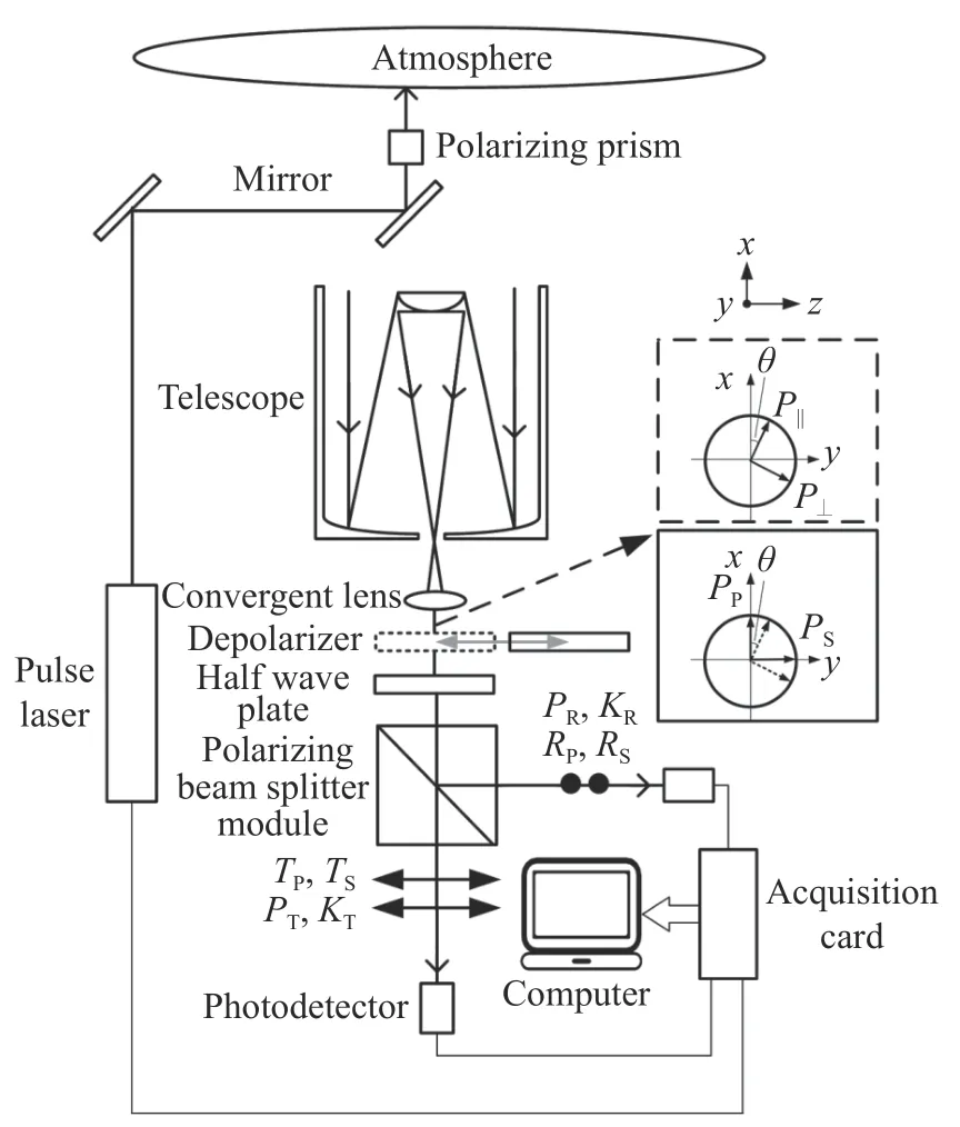
Fig. 1 Basic principle and structure diagram of polarization lidar system图1 偏振激光雷达系统基本原理与结构图
As shown in Fig. 1. the vertical componentP⊥and parallel componentP‖of echo signal can be decomposed into the following components after the coordinate rotation transformation relative to the incident plane of PBS:

where the subscriptsS′andP′respectively represent the directions perpendicular to and parallel to the incident plane of PBS, andθrepresents the angle between the laser polarization vector and the incident plane of PBS (here referred to as misalignment angle).
Because there is polarization crosstalk in the actual PBS, the parametersRP,RS,TPandTSrespectively represent the reflectance and transmittance ratios of P and S light in PBS (the above four parameters are generally known, and are labeled by PBS manufacturer). After the light passes through the PBS, the detected powerPRandPTin the reflection channel and transmission channel can be expressed as

whereKRandKTrespectively represent the gain coefficients of reflection channel and transmission channel,G=KR/KT. According to the Eq. (3), the actually measured depolarization ratio δ∗(θ) can be obtained:
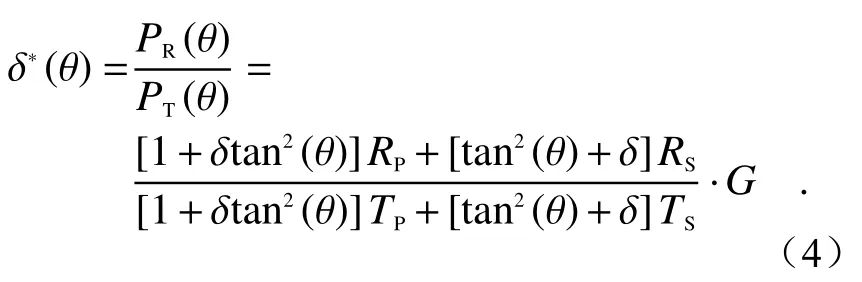
It can be seen from the equations (1) ~ (4) that the gain ratioGmust be calibrated before the calculation of the depolarization ratio, and that the gain ratio calibration error will affect the calculation result of the depolarization ratio[10]. Next, we will introduce several typical gain-ratio calibration methods.
3 Gain ratio calibration methods
3.1 Method of clean atmospheric molecule
The method of clean atmospheric molecule is a method to calibrate the gain ratio by comparing the actual depolarization ratio of clean atmosphere detected by the system and the theoretical depolarization ratio of clean atmosphere, assuming that only atmospheric molecules (no aerosols and clouds) exist in the high air. The calculation formula of depolarization ratio in the method of clean atmospheric molecule is
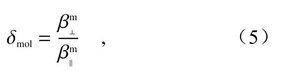
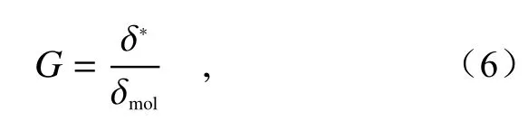
where δ∗and δ respectively represent the atmo
molspheric molecular depolarization ratio actually measured at the altitudercand the theoretical atmospheric molecular depolarization ratio. δmolcan be calculated according to the theory of atmospheric scattering[11], but it is not fixed. Atmospheric molecular scattering is mainly composed of Rayleigh scattering and vibration Raman scattering (with a negligible intensity). Rayleigh scattering is mainly composed of pure rotational Raman line and central Cabannes line[12]. In the Rayleigh scattering spectrum, Cabannes lines constitute the central peak of Doppler broadening, while pure rotational Raman lines are distributed on both sides of Cabannes lines to constitute the sidebands[13]. The depolarization effect caused by pure rotational Raman lines is much greater than that caused by Cabannes lines. For a li dar system, the value range of δmolis between 0.003 63~0.014 3 when the filters with different bandwidths (BWs) are used[10]. If the filter bandwidth in the lidar system is narrow (BW<0.3 nm@532 nm), δmolwill be the lower limit, namely δmol=0.003 63. Conversely, if the filter bandwidth is wide (BW=15 nm@532 nm), δmolwill be the upper limit, namely δmol=0.014 3.
Due to convenient operation and no need to add other devices to the light path of the system, the method of clean atmospheric molecule was widely used in the 1980s and 1990s. However, its shortcoming is also very obvious. Because clean atmosphere rarely exists, the calibration result obtained from a calibration area with aerosols or clouds present will have a large error. Moreover, when the filter bandwidth ranges from 1 nm to 15 nm, the proportion of pure rotational Raman lines in the scattered atmospheric molecules cannot be accurately evaluated. This may lead to the inaccurate calculation of the theoretical depolarization ratio of clean atmosphere, resulting in a calibration error. In addition, it should be noted that the method of clean atmospheric molecule is generally applicable to the lidar with a laser wavelength of less than 550 nm.For the lidar with a detection wavelength of more than 800 nm, this calibration method is likely to cause a large calibration error because the Rayleigh scattering intensity is weak[13]. Therefore, this method is rarely used at present.
3.2 +45° method
+45° method is a method of placing a Half-Wave Plate (HWP) in the receiving optical path(generally in front of PBS) and rotating it in one direction (clockwise/counterclockwise) to realize the gain ratio calibration. In particular, this method assumes that the properties of HWP are ideal and that the atmospheric state does not change during calibration. In addition to the above two basic assumptions, two more assumptions should be added to the+45° method, that is, neither a misalignment angle nor polarization crosstalk will exist[14].
As shown in Fig. 2 (Color online), the HWP is placed in the upstream optical path of PBS. In this case, the laser polarization vector is considered to be parallel to the incident plane of PBS, as shown in Fig. 2(a).
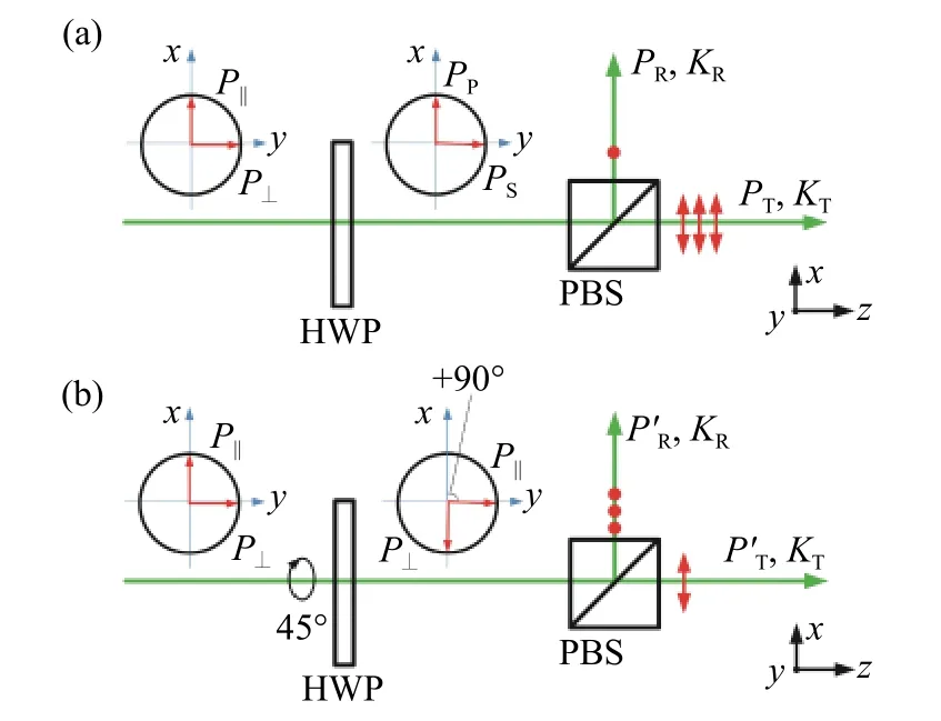
Fig. 2 Schematic diagram of +45° method. (a) Before HWP rotation. (b) After HWP rotation by +45°图2 +45°法原理图。(a)半波片旋转之前;(b)半波片旋转+45°之后
Since the impact of misalignment angle and polarization crosstalk is not considered, the Eq. (3)can be simplified as
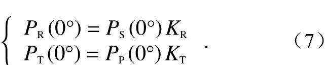
Then, the HWP is rotated clockwise around the optical axis (similar to the counterclockwise case),so the angle between the laser polarization vector and the incident plane of PBS is +90°, as shown in Fi g. 2(b). In the Eq. (7),PT(0°) becomes(90°).The specific formula is not repeated here. In this case, the gain ratioGcan be expressed as
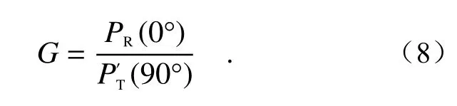
The advantage of this method is easy operation.Its disadvantage is that the alignment angle error and polarization crosstalk error can be easily introduced as the effects of misalignment angle and polarization crosstalk are ignored.
3.3 ±45° method
±45° method is a method of placing a HWP in the receiving optical path and rotating it twice (by+22.5° and −22.5° respectively relative to the initial position) to realize the gain ratio calibration. This method was proposed by Freudenthaleret al. from the University of Munich, Germany[15]. Based on the+45° method, the ±45° method has considered the effects of both misalignment angle and polarization crosstalk. As shown in Fig. 3 (Color online).
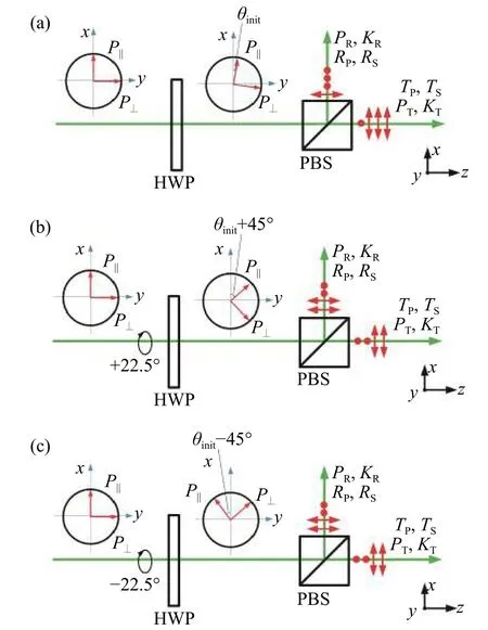
Fig. 3 Schematic diagram of ±45° method. (a) Before HWP rotation. (b) After HWP rotation by +22.5°.(c) After HWP rotation by −22.5°图3 ±45°法原理图。(a)半波片旋转之前;(b)半波片旋转+22.5°之后;(c)半波片旋转−22.5°之后
In Fig. 3, a HWP is placed in the upstream optical path of PBS. It is assumed that there is an initial misalignment angle θinitbetween the laser polarization vector and the incident surface of PBS, and that θhis the quantitative misalignment angle introduced artificially.
After the HWP rotation, the following equation can be derived from Eq. (4):
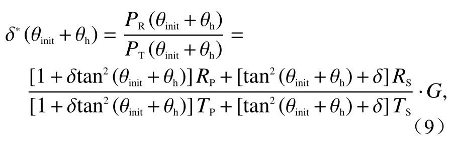
In order to reduce the influence of initial misalignment angle θinit, the HWP is rotated twice continuously in the ±45° method. At first, the HWP is rotated by +22.5° clockwise around the optical axis relative to its initial position. Then, the HWP is rotated by −45° counterclockwise around the optical axis based on the first rotation, or by −22.5° counterclockwise around the optical axis relative to its initial position. In the two rotations, the angles between the laser polarization vector and the incident surface of PBS are +45° and −45° respectively.At this time, the gain ratioGcan be expressed as

It can be seen from Eq. (10) that in the ±45°method, the polarization crosstalk error of PBS is considered, but the influence of alignment angle error cannot be completely eliminated. It is proved by facts that the error source has little to do with the Signal-to-Noise Ratio (SNR) in the ±45° method[16].If θinit= 1°, the relative error ofGcan be controlled within 5%[15]. With the advantages of simple operation and high accuracy, the ±45° method has been used in MULIS (Multichannel Lidar System), POLIS (Portable Lidar System) and other high-precision polarization lidar systems for gain ratio calibration[16]. Its shortcoming is that the alignment angle error cannot be eliminated.
3.4 ∆45° method
∆45° method is a method of placing a HWP in the receiving optical path and rotating it by 45° in one direction (clockwise/counterclockwise) to realize the gain ratio calibration. This method has the same operation as +45° method, but different calculation approach. In addition, it doesn’t need initial 0° search. This method was proposed by Luo Jinget al. from Zhejiang University[17], as shown in Fig. 4(Color online).
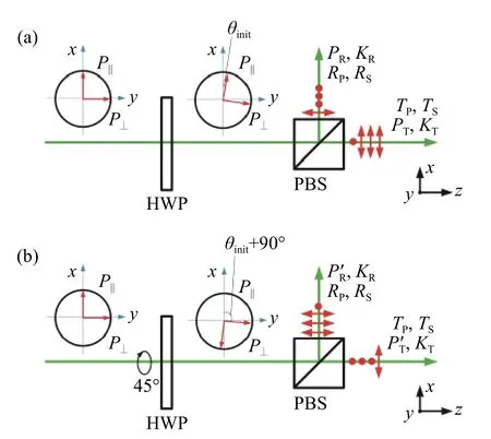
Fig. 4 Schematic diagram of ∆45° method. (a) Before HWP rotation. (b) After HWP rotation by 45°图4 ∆45°法原理图。(a)半波片旋转之前;(b)半波片旋转45°之后
In Fig. 4, a HWP is placed in the upstream optical path of PBS. It is assumed that there is an initial misalignment angle between the laser polarization vector and the incident surface of PBS.
Before the HWP rotation, the following equation can be derived from Eq. (4):
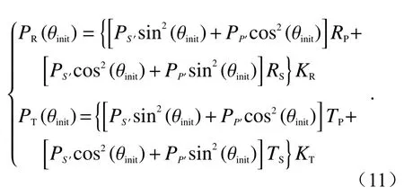
Then, the HWP is rotated around the optical axis, as shown in Fig. 4(b). After rotation, the termsPR(θinit) andPT(θinit) in Eq. (11) turn intoand. The specific formula is not repeated here. In this case, the gain ratio can be expressed as

3.5 Rotation fitting method
Rotation fitting method is a method of placing a HWP in the receiving optical path and rotating it for several times to realize the gain ratio calibration through the nonlinear least square fitting and the inversion of gain ratio, depolarization ratio and initial misalignment angle θinit[18]. This method was proposed by Alvarezet al. from NASA.
As shown in Fig. 5 (Color online), a HWP is placed in the upstream optical path of PBS. It is assumed that there is an initial misalignment angleθinitbetween the laser polarization vector and the incident surface of PBS.
If the HWP is rotated artificially by θh,j/2 relative to its initial optical axis, a series of misalignment angles θh,jcan be introduced artificially and quantitatively. From Eq. (9), the following equation can be derived:
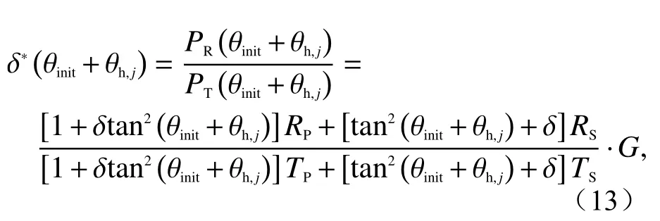
wherejrepresents thej-th rotation of the HWP. In the Eq. (13), asandTScan be considered as known quantities, only three quantities, namely gain ratioG, initial misalignment angle θinitand theoretical depolarization ratio δ, are unknown. In this case, the three unknowns cannot be solved by a single equation. However, multiple equations can be obtained by rotating the HWP for many times. Then the nonlinear least square method can be used to solve the equation set so as to solve the three unknowns. It should be noted that at least three equations need to be obtained in this method, namelyj≥3.
The advantage of this method is that the three unknowns, namely gain ratio, depolarization ratio and initial misalignment angle, can be inverted simultaneously through one calibration, and no a priori value is required. However, due to time-consuming calibration and complicated operation, this method is only suitable for a relatively stable atmospheric environment.
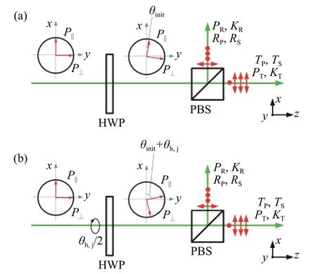
Fig. 5 Schematic diagram of rotation fitting method. (a)Before HWP rotation. (b) After HWP rotation by θh,j图5 旋转拟合法原理图。(a)半波片旋转之前;(b)半波片旋转θ h,j角之后
3.6 Pseudo-depolarizer method
The pseudo-depolarizer method is a method that adds an optical element to the optical path to convert the echo signal received by the system into unpolarized light so as to realize the gain ratio calibration. The gain ratio is calibrated by using the ratio of signal intensities of two detection channels. From Eq. (4), the gain ratioGcan be obtained:

A typical example is found in the CALIOP,where the non-depolarizing signal generated by a depolarizer is used for gain ratio calibration[19]. The specific operation procedure is as follows. A movable depolarizer is placed in the upstream optical path of PBS during the system calibration, and is removed after the calibration completion, as shown in Fig. 6. In the CALIOP, this method is used to calibrate the gain ratio of the system on orbit at night and then the method of clean atmospheric molecule is used to verify the calibration result[20].
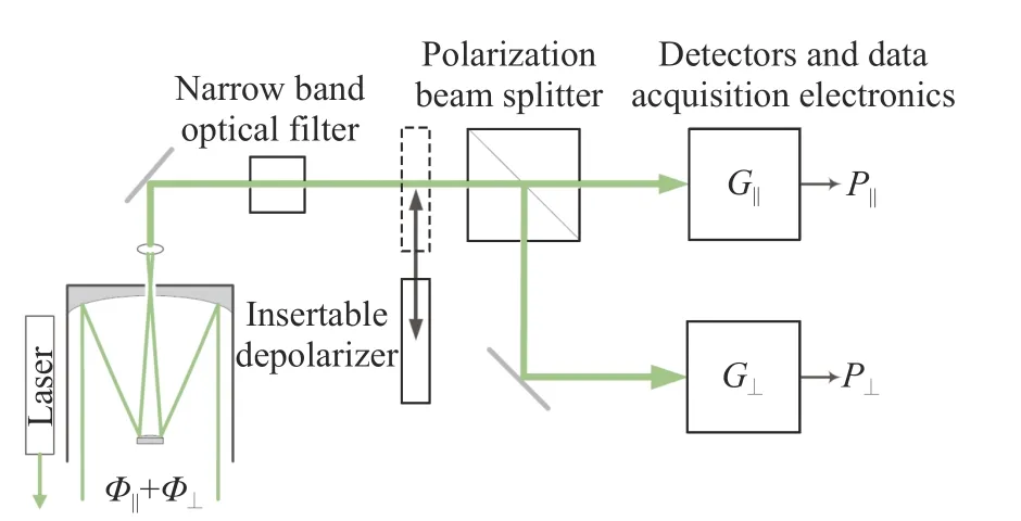
Fig. 6 Schematic diagram for CALIOP gain ratio calibration图6 CALIOP增益比定标原理图
The advantage of this method is that it can be operated easily and calibrated in real time, so as to eliminate the influence of atmospheric state change.Its disadvantage is that other errors will be introduced easily due to the difficulty for a commercial depolarizer to produce completely depolarized light.
4 Experimental results and analysis
The polarization lidar used in the experiment is a typical dual-channel lidar, whose structure is shown in Fig. 1 (where the same device is only marked once). The pseudo-depolarizer between the convergent lens and the HWP is only used in the pseudo-depolarizer method. To reduce linear polarization error, a polarizing prism was added to the emergent light path in the experiment system, so that the extinction ratio of the outgoing laser reached 2×10⁵∶1. To reduce the polarization crosstalk error, a PBS was glued with a polarizing film to achieveTP:TS(RS:RP)>30 000∶1. Therefore, the effect of alignment error on gain ratio is discussed instead of the effect of linear polarization error and polarization crosstalk error. The specific parameters of the system are shown in Table 1.
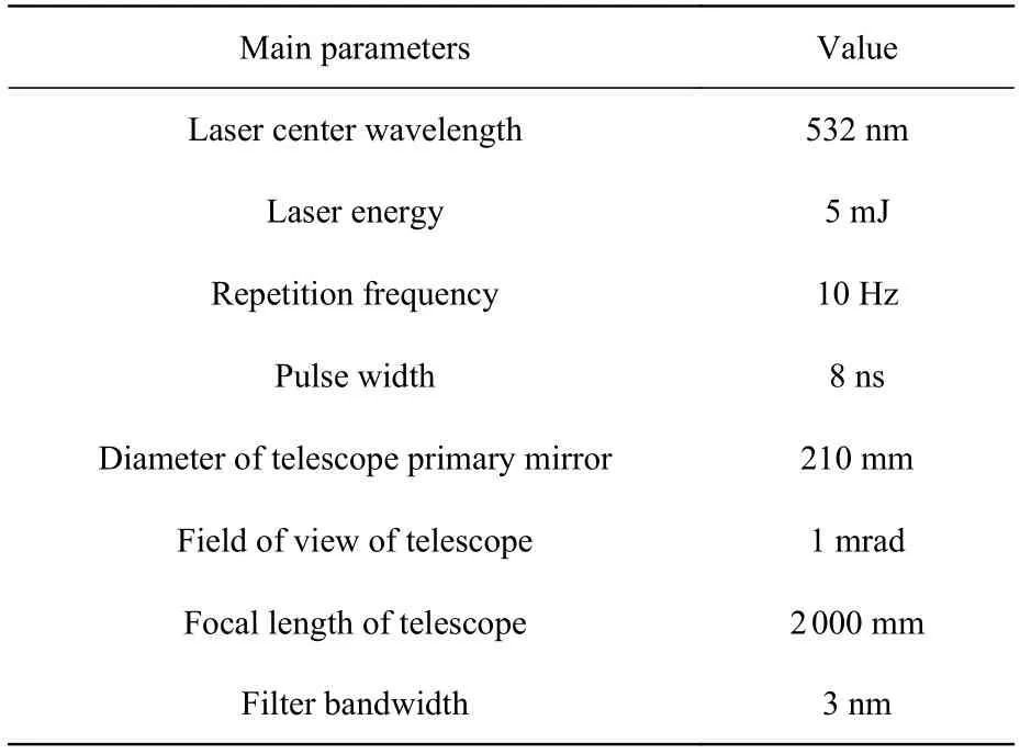
Tab. 1 Main parameters for polarization lidar system表1 偏振激光雷达系统主要参数
Due to the large calibration error of clean atmospheric molecules, the experiment in this paper mainly compares the influence of five methods,namely, +45° method, ±45° method, ∆45° method,rotation fitting method and pseudo-depolarizer method, on the gain ratio calibration at different misalignment angles (alignment angle errors).
To ensure a high signal-to-noise ratio, the experiment was carried out at night. Meanwhile, in order to reduce the impact caused by atmospheric changes, the detection in horizontal direction (pitch angle: 0°) was adopted. After the optical axis calibration of the system was completed, an electric rotating motor (accuracy: 0.005°) was used to adjust the half-wave plate to the position where the laser polarization vector was parallel to the incident surface of PBS (when 200 signals on average were passed and the maximum power of transmission channel was detected visually). At this point, the HWP angle was the initial 0°. It should be noted that, for the convenience of description, the initial misalignment angle θinitis not included in the actual total misalignment angle when the misalignment angle θhis introduced artificially and quantitatively to the following section. However, each actual misalignment angle contains the initial misalignment angle θinit(an unknown quantity). Then, withθh=0°(the actual misalignment angle is θinit+0°) as the zero point, an electric rotating motor is used to rotate the HWP. In the actual operation, the alignment angle usually does not exceed 15°[21-22]. However, to ensure the experiment integrity, the misalignment angle under discussion is expanded to 45° in this paper.
In the +45° method, ±45° method, ∆45° method and rotation fitting method, the HWP was rotated with a step size of 2.5° within the θhrange of−45°~67.5° to obtain a total of 46 sets of original echo signals. By processing the above data, a step size of 5° and a θhrange of −45° ~ +45° (that is, the difference between the two angles in each group of data before and after the HWP rotation are 45°)were selected in the four methods. After calculation,a total of 19 groups of gain ratio data were obtained.
Before starting the experiment, a pseudo-depolarizer was added to the optical path of the system, as shown in Fig. 1. Since the pseudo-depolarizer was not ideal, the HWP was rotated with a step size of 10° within the θhrange of −80°∼+100° to obtain a total of 19 sets of original echo signals in order to observe the change of pseudo-depolarizer in at least one cycle. By processing the above data, a total of 19 groups of gain ratio data were obtained after calculation.
The calibration results of the above five methods are given in Table 2 (θh=0 °).

Tab. 2 Calibration results of five methods atθh=0◦表2 θh=0◦时5种方法的定标结果
As can be seen from Table 2, when there is no misalignment angle (θh=0 °), the calibration results of±45° method, ∆45° method and rotation fitting method are close to each other and can be considered closest to the true value. Therefore, the average value of the gain ratios measured by the above three methods at θh=0 ° is defined as the true value.The curves of the relative errors of the five calibration methods changing with the misalignment angle are shown in Fig. 7 (the calculation processes of rotation fitting method and pseudo-deflector method are described in detail in the Sections 4.2 and 4.3).
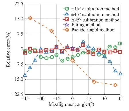
Fig. 7 Relative errors changing with the misalignment angle for the five calibration methods图7 5种定标方法相对误差随对准偏失角的变化曲线
4.1 +45°, ±45° and ∆45° methods
As shown in Fig. 7, when |θh|<15°, the calibration results of ±45° method and ∆45° method are similar with a small relative error. However, even if the misalignment angle is 0°, the calibration result of +45° method is still greatly different from those of the above two methods, with a relative error up to 4%. When |θh|>15°, the calibration results of +45°method and ∆45° method will remain almost stable.However, with the increase of misalignment angle,the calibration result of ±45° method will become more unstable and its relative error will increase sharply even up to 12.93%. The main reason for such error distribution is that the ±45° method calculates the geometric average of the two measurements before and after rotation, while the ∆45°method calculates the arithmetic average of the two measurements before and after rotation based on the+45° method. The reasons for the above phenomena of +45° method will be explained below through specific theoretical analysis.
The relative error between the two methods was analyzed[23-24]. The powers detected in the reflection channel and transmission channel before and after the HWP rotation in the two methods are denoted asand. Then
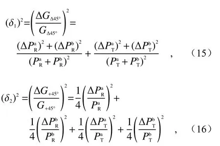
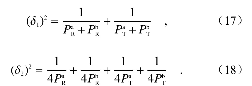
where δ1and δ2represent the relative errors of the calibration results of ∆45° method and ±45° method,and(SisRorTandnisaorb) represents the uncertainty (standard deviation) in each measured value. The photon counting signal in lidar can be considered to be subject to Poisson distribution[25-26],so the statistical error is equal to the root mean square of the mean value of the signal, i.e.Therefore, the equations (15) and (16) can be further deduced as follows
4.2 Rotation fitting method
Considering that the error of misalignment angle was not greater than 15° in the actual process,13 sets of data satisfying |θh|≤ 15° (that is, θh,j= 0°,±2.5°, ±5° ··· ±15°) were selected for fitting. The calculation results of rotation fitting are shown in Fig. 8 (Color online). According to Eq. (13), solving the three unknowns (gain ratioG, initial misalignment angle θinitand theoretical depolarization ratio δ) in the equations is a nonlinear least square problem. Before solvingG, θinitand δ, their initial values need to be predicted. Their optimum initial predicted values are shown in Fig. 8.
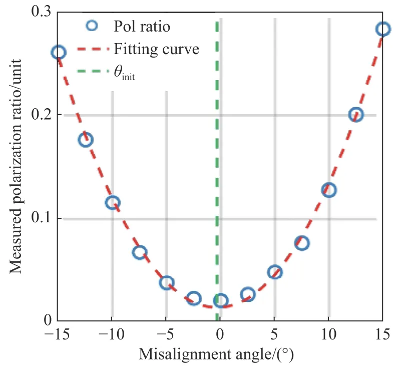
Fig. 8 Curve of the actually measured depolarization ratio changing with the misalignment angle, where the blue circle represents the δ∗(θ) values measured at different θ angles, and the red and green dotted lines represent the fitting curve and θ init, respectively图8 实际测量退偏比随对准偏失角的变化曲线图。其中蓝色圆圈代表在不同θ 情况下测量的 δ∗(θ),红色虚线代表拟合曲线,绿色虚线代表θinit
It can be found that the relationship betweenand θh,j(blue circle) can be approximately represented by a quadratic polynomial[27].Therefore, the following quadratic polynomial is constructed with the artificially and quantitatively introduced misalignment angle θh,jas an independent variable and the actually measured depolarization ratioas a dependent variable:

whereA0,A1andA2are quadratic polynomial coeffici ents. The fitting result is shown as the red dotted line in Fig. 8. The minimum value of the quadratic polynomial represents the initial misalignment angle θinit, whose result is calculated to beθinit=−A1/(2×A2)= −0.35°. This value can be used as the optimum initial predicted value of θinit. Then, θinit=−0.35° is substituted into Eq. (13) and the equation set is solved with nonlinear least square method to obtain the gain ratio, namelyG=1.2716.
4.3 Pseudo-depolarizer method
The calculation result of pseudo-depolarizer method is shown in Fig. 9 (Color online), in which the blue circles represent the gain ratios calculated at different angles of the HWP. It can be observed that the distribution of blue circles is in line with the cosine curve distribution law. Therefore, the following cosine function polynomial is constructed with the HWP rotation angle φ (θh=2φ) as an independent variable and the gain ratioGas a dependent variable:

whereB0,B1,B2andB3all represent the coefficients of the cosine function polynomial. The fitting result is shown as the red dotted line in Fig. 9.
Theoretically, if the echo signal is completely unpolarized light, its state will remain unchanged,irrespective of how the HWP angle is changed. In other words, the rotation of HWP will not affect the value of gain ratio. The result of gain ratio calibration should be represented by a line parallel to thexaxis, rather than by a cosine curve as shown in Fig. 9. The reason for this problem is that the existing commercial depolarizer cannot completely transform the polarized light into unpolarized light, so that the echo signal still contains part of the polarized light after passing through the depolarizer.When using laser as the light source to test the depolarizing effect of a depolarizer, Luo Jing et al.from Zhejiang University found that the test result was similar to the cosine distribution in Fig. 9[28].This indicates that the result of gain ratio calibration will still be affected by this portion of polarized light even if the misalignment angle is 0°.

Fig. 9 Gain ratio calibration result of pseudo-depolarizer method. The blue circles represent the gain ratios measured at different misalignment angles, and the red dotted line represents the cosine polynomial fitting curve图9 退偏器法增益比定标结果。蓝色圆圈代表半波片在不同角度下测量的增益比,红色虚线代表余弦函数多项式拟合曲线
It should be noted that among the measurement data obtained by pseudo-depolarizer method,only 5 sets of data satisfy θh= −45° ~ +45°. Therefore, only 5 points are marked in Fig. 7 according to this method. At θh= 0°, the relative error of pseudodepolarizer method is 5.6%. This indicates that the result of gain ratio calibration will still be affected by this portion of polarized light even if the misalignment angle is 0°.
4.4 Discussion
Through the analysis of experimental results,we know that the calibration results of ±45° method,∆45° method and rotation fitting method are the most accurate. This is consistent with the above theoretical analysis result. However, the error of ±45°method will increase with the misalignment angle.The rotation fitting method is only suitable for a relatively stable atmospheric environment due to timeconsuming calibration and complicated operation. In comparison, ∆45° method has obvious advantages:easier operation, robust calibration results not affected by misalignment angle, and no need to search for the initial 0° angle. However, ∆45° method cannot eliminate the influence of atmospheric state changes. In contrast, the pseudo-depolarizer method is not only easy to operate, but also capable of eliminating the influence of atmospheric state changes and free from the problem that multiple HWP rotations will increase the accumulated angle error. But so far, the commercial depolarizer still cannot produce completely depolarized light, which will introduce a new error that is difficult to evaluate. In conclusion, we suggest the use of ∆45° method for calibration as a general rule and the use of pseudo-depolarizer method for calibration when a high-precision depolarizer is available.
5 Conclusion
The calibration accuracy of gain ratio has a great influence on the detection accuracy of polarization lidar. This paper compares a variety of the existing gain-ratio calibration methods theoretically and experimentally for the first time, and provides some suggestions on the selection of gain-ratio calibration methods.
As far as the operability is concerned, the pseudo-depolarizer method only needs a depolarizer inserted into the system to realize the calibration, and can eliminate the influence of atmospheric state changes. The other four methods require at least two rotations of the HWP in relatively complicated operation and cannot eliminate the influence of atmospheric state changes. In terms of calibration accuracy, this experiment mainly compared the influence of +45° method, ±45° method, ∆45°method, rotation fitting method and pseudo-depolarizer method (excluding the method of clean atmospheric molecule due to its large calibration error)on the gain ratio calibration at different misalignment angles. The experimental results show that the calibration accuracy of ±45° method, ∆45° method and rotation fitting method is relatively high, but the operation of ±45° method and rotation fitting method is quite complex. The error of ±45° method is big when the misalignment angle is large. In the ∆45°method, the result of gain ratio calibration is not affected by the misalignment angle, and there is no need to search for the initial 0° angle. Compared with the first three methods, +45° method has a larger error when the misalignment angle is 0°. The pseudo-depolarizer method is greatly affected by the use of non-ideal depolarizer. If an ideal depolarizer is available, this method will be an ideal gain-ratio calibration method. By comparing different gain-ratio calibration methods theoretically and experimentally, this paper gives the best choice of gain ratio calibration method, suggesting the use of ∆45°method for calibration as a general rule and the use of pseudo-depolarizer method for calibration when a high-precision depolarizer is available.
——中文对照版——
1 引 言
偏振激光雷达是激光雷达家族中最早的成员之一,自1971年诞生以来,其已广泛应用于大气云及气溶胶探测[1]。偏振激光雷达反演得到的退偏比可用于区分球形粒子和非球形粒子,故其常被应用于气溶胶的类型识别及云的热力学相态识别[2]。不仅如此,退偏比也可用于识别对流层的边界层以及从形态学上区分极地平流层云与其它种类云[3-5]。同时,退偏比还可以用于研究沙尘的长距离传输特性[6]。可见……
