Atomic magnetometer with microfabricated vapor cells based on coherent population trapping∗
2021-03-19XiaojieLi李晓杰YueShi史越HongboXue薛洪波YongRuan阮勇andYanyingFeng冯焱颖
Xiaojie Li(李晓杰), Yue Shi(史越), Hongbo Xue(薛洪波),Yong Ruan(阮勇),5,†, and Yanying Feng(冯焱颖),‡
1State Key Laboratory of Precision Measurement Technology and Instrument,Tsinghua University,Beijing 100084,China
2Key Laboratory of Photonic Control Technology(Ministry of Education),Tsinghua University,Beijing 100084,China
3Department of Precision Instrument,Tsinghua University,Beijing 100084,China
4State Key Laboratory of Space Weather,National Space Science Center,Chinese Academy of Sciences,Beijing 100190,China
5MEMS Institute of Zibo National High-tech Industrial Development Zone,Zibo 255086,China
Keywords: atomic magnetometer,MEMS,vapor cell,coherent population trapping
1. Introduction
Atomic sensors have been widely served as precision measurement sensors in various applications, such as atomic clocks, magnetometers, and gyroscopes.[1,2]Measuring magnetic fields enable a characterization for many significant physical phenomena in many fields of science, including physics, geology and biology.[3-5]Traditionally, magnetometry with a sensitivity in the fT range depends on lowtemperature superconducting quantum interference device(SQUID) magnetometers.[6]However, SQUIDs need expensive liquid helium maintained in a superconducting state, resulting in huge size and high maintenance costs. With no requirement for cryogenic equipment, atomic magnetometers have been recognized as a potential candidate for SQUIDs in the applications needing ultra-low noise magnetic sensors like biomagnetic measurement.[7-10]
On the other hand, the potential of atomic magnetometers in chip-scaled integration and wafer-level fabrication endows them to have advantages in field applications and enlarges the applying scope of ultra-sensitive magnetometers.Recent progresses of MEMS technology on fabricating atomic sensors, especially microfabricated vapor cell,have leaded to demonstrations of chip-scaled atomic magnetometers.[11-14]A representative chip-scale atomic magnetometer has been constructed with a sensitivity of 50 pT/Hz1/2at 10 Hz by Schwindt et al. in 2004.[12]With the advantages of size and power consumption, chip-scale atomic magnetometers can maintain performances in terms of stability and sensitivity.[15-17]
In this work,an atomic magnetometer based on the CPT effects in microfabricated vapor cells is demonstrated. These cells were designed and fabricated with wafer-level fabrication technology in our previous works.[18-20]The performance of these microfabricated vapor cells is characterized and the potential as a core component for a chip-scale atomic magnetometer is evaluated. A closed-loop atomic magnetometer based on the microfabricated vapor cell is built and measured.
2. Theory on CPT
CPT was first demonstrated by Alzetta et al. when they detected dark lines in the fluorescence emitted by a beam of sodium atoms in 1976.[21]The phenomenon is induced by the interaction between atom and two phase-coherent light fields E1and E2at frequencies ω1and ω2,respectively. The threelevel atomic levels and light fields,forming a Λ configuration,are shown in Fig.1(a). When the beat frequency between the two resonant laser fields exactly equals the atomic ground state hyperfine splitting Δ,i.e.,ω1−ω2=Δ,atoms are driven into a coherent superposition state of the two ground state levels and absorb no photons anymore,called the dark state.
Before interacting with light, the atomic population is equally distributed between two low energy states,|b〉and|c〉.During the interaction with light,the atoms are excited to state|a〉,and then spontaneously decay either into the dark state or into its orthogonal counterpart,the bright state. The atoms in the dark state do not interact with the laser fields and remain in this state, while the atoms in the bright state interact until all atoms end up in the dark state. After such a steady state is achieved,the atomic medium becomes transparent,because both resonant light fields propagate without any optical losses,which is called the coherent population trapping effect.[22]
The full width at half maximum(FWHM)of the CPT resonance line,shown as Lorentzian shape,reads[23,24]

where γ2is the hyperfine coherence relaxation rate,Γ⋆the decay rate from the excited state or linewidth of the optical resonance,which increases with the buffer gas pressure,and ωRthe optical Rabi pulsation related to the laser intensity I.
As shown in Eq. (1), the CPT resonance linewidth increases linearly with laser intensity in a slope proportional to the inverse optical linewidth. The zero-intensity limit is only given by the ground state coherence. Because the spontaneous radiative decay between two hyperfine states of the same ground state is strictly forbidden, an atom in the dark state can maintain its coherence state until it interacts with its environment, such as atomic collisions with glass wall of a vapor cell. Filling a pressure of buffer gases in the cell can reduce the diffusive motion of atoms and makes it possible to preserve the ground state coherence,meaning the decrease of FWHM.
Based on the magnetic sensitivity of the CPT resonances in vapor cell (with buffer gas), an atomic magnetometer can be demonstrated with a high sensitivity. Figure 1(b)shows the schematic of light-induced two-photo transitions of D1 line of87Rb atom from Fg=1,2 to Fe=2 in the case of σ-σ transition scheme. The two-photo transitions between two ground states Fg=1,mF=−1/1 with Fg=2,mF=−1/1 is affected by the Zeeman level splitting. Under weak magnetic conditions,the energy between the ground state Zeeman level with the mF=n can be written as

where ν0−0is the energy of atomic ground state hyperfine splitting,γ the gyromagnetic ratio,and B the magnetic field.
As shown in Eq.(2),the value of νn−nis proportional to magnetic field magnitude B. The 0-0 central resonance signal is called the clock transition, meanwhile the −1-−1 and 1-1 signals are magnetic-sensitive resonance transition. By decreasing the FWHM of these CPT resonance peaks,the resolution of frequency measurements of the hyperfine or Zeeman resonance can be improved and leads to more sensitive magnetic field measurement.
3. Experimental setup
Figure 1(c)shows the schematic of the experimental apparatus. A 795 nm external cavity diode laser (ECDL, DL pro, TOPTICA) is locked to resonance transition of Fg=1 to Fe=2 of87Rb D1 line,with Zeeman modulation frequency stabilization technology.After coupled into an optical fiber via a fiber coupler, the light is modulated by a fiber electro-optic modulator (FEOM,PM-0S5-10-PFA-PFA, EOSPACE) driven at 6.834 GHz by an RF microwave source (N5181A, AGILENT),and the phase-coherent light for the CPT resonance is formed with two different frequencies. A linear polarizer and quarter wave plate are used to generate the circular polarization light for the σ-σ transition scheme. Then the light passes the microfabricated vapor cell placed in a five-layer magnetic shields, and is detected by a photodiode (PDA36A, THORLABS).The resonance error signal is acquired with a lock-in amplifier (LIA, LIA-MVD-200-H, FEMTO). A signal generator (33522B, KEYSIGHT) provides the reference signal for the microwave generator and LIA loop. The CPT signal from LIA is acquired by a data acquisition board(DAQ)for closedloop control. Finally, the system is closed-loop locked by a PID error compensation control.
Microfabricated Rb vapor cells are fabricated using twostep glass-silicon anodic bonding techniques and dispenser pills of SAES Getters,containing both85Rb and87Rb.[20]As shown in Fig.1(d), these cells have a dual-cavity structure with an optical cavity and a reaction cavity. The square reaction cavity contains the dispenser pill and act as a reservoir of Rb atoms, while the cylindrical one with radius size of about r=2.5 mm acts as the optical cavity for CPT detection. The two cavities are connected via a micro channel. Two cells are used in the experiments,labeled as 1 and 2,respectively. The pressure of buffer gas in cell 1 is about 8.9 kPa in 90◦C,while that of cell 2 is about 4.0 kPa.
The microfabricated vapor cell is placed in the center of the magnetic shields and magnetic coils,which provides a bias static magnetic field along the direction of light. A heating system including intermittent electrical heating and high frequency electrical heating is utilized to heat the cells up to about 90◦C. The heating current is turned off while collecting the data of CPT signal, thus the interference caused by electric heating can be negligible.
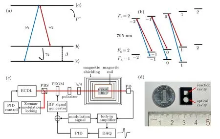
Fig.1. Schematic diagrams of the theory and apparatus. (a) The interaction of light with three-level atom in a Λ configuration. (b) Lightinduced two-photo transitions of D1 line of 87Rb atoms in the case of σ-σ transition scheme. (c)CPT resonance measurement apparatus in the case of σ-σ transition scheme. ECDL:external cavity diode laser;PBS:polarization beam splitter;FEOM:fiber electro-optic modulator;Polarizer: linear polarizer;λ/4: quarter wave plate;PD:photodiode. (d)The experimental microfabricated vapor cells with the radius size of optical cavity about 2.5 mm.
4. Results and discussion
A typical experimental absorption spectrum obtained in the cells operating in about 90◦C is shown in Fig.2, where four peaks correspond to four atomic transitions of natural abundance rubidium. The buffer gas in the cells broadens the absorption spectrum because of the collision between Rb atoms and Ne atoms. With the increase of the buffer gas pressure, the absorption line broadening gradually increases, as shown in Fig.2. Due to the higher pressure of buffer gases,the absorption peaks of cell 1 have wider line width than those of cell 2,and even a peak of87Rb overlapped with the peak of85Rb nearby in cell 1.

Fig.2. The experimental absorption spectrum obtained in the microfabricated vapor cells 1 and 2 operating in about 90 ◦C.The absorption peaks are broadened clearly.
To obtain the CPT resonance, the laser is modulated by applying 6.834 GHz high-frequency signal from the RF microwave source to the FEOM.The CPT spectrum is acquired by sweeping the frequency. In the presence of a bias magnetic field,the CPT spectrum will have three separated Zeeman resonance peaks.The frequency of RF microwave source is modulated by a sine signal in addition to its frequency sweep and a lock-in amplifier is used to get the corresponding error signal of the CPT line. Experimentally,Fig.3 shows the Zeeman spectrum and its corresponding error signal in cell 2.
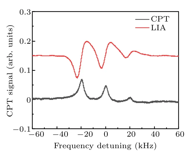
Fig.3. The typical experimental Zeeman spectrum and its corresponding error signal obtained in the Rb-Ne microfabricated vapor cell 2.The CPT 0-0 resonance linewidth is about 4.2 kHz.
The laser intensity is 4.1 µW with the beam waist size approximately covering the optical cavity of cell. The static magnetic field B is about 1.4 µT, so the frequency shift of the 1-1 resonance with the 0-0 resonance is calculated to be about 20.3 kHz, which is matched with the results in Fig.3.The CPT 0-0 resonance linewidth is about 4.2 kHz. The amplitude of −1-−1 resonance peak is higher than that of 1-1 resonance, due to optical pumping effect in the case of σ-σ transition scheme. It can be shown that the Ne buffer gas reduces the CPT line-width efficiently, compared with those of cells without buffer gas,which can be several hundreds of kHz correspondingly.
Figure 4 shows the effect of the cell temperature on the linewidth of the 0-0 resonance for the cells 1 and 2.

Fig.4. The effect of the cell temperature on the linewidth of the 0-0 resonance for the cells 1 and 2. The CPT line widths are increased with the rising temperatures for both cells.
With the rising temperature,the CPT line widths increase for both cells.This is due to the increase of the total relaxation rate of the vapor cell when the atomic density and velocity increase with the temperature,and rubidium atoms collide with the cavity wall or other atoms more frequently. Owing to the higher buffer gas pressure in cell 1, the FWHM of cell 1 is smaller than that of cell 2 at the same temperature. There is not an optimal value for the effect of cell temperature on the CPT line width at the temperatures in our experiment. The CPT line widths increases with the rising temperature. However,the amplitude of the CPT signal has an optimization point around 90◦C.For optimizing the signal-to-noise ratio(SNR)of the CPT signal,the operation temperature of the cell in the atomic magnetometer is set to 90◦C.

Fig.5. The linewidth of CPT resonance versus the total laser intensity for two Rb-Ne microfabricated vapor cells. The CPT linewidth linearly increases with laser intensity due to power broadening.
The laser intensity of pump light can also broaden the linewidth of CPT resonance. Figure 5 shows the linewidth of CPT resonance versus the total laser intensity for these two Rb-Ne cells. According to Eq. (1), the CPT linewidth linearly increases with laser intensity due to power broadening. Fit functions of the linewidth-intensity dependence are(3.65+0.20I)kHz and(1.46+0.11I)kHz for the cells 1 and 2, respectively. The ultimate linewidth of cell 1 can reach 1.46 kHz with approximately zero laser intensity. The slope of the increase is lower for the cell 1 with higher buffer gas pressure,because the optical linewidth,Γ⋆,increases with the buffer gas pressure.
Frequency modulation(FM)mode is used in the RF signal source with modulation frequency at 2.5 kHz to enable phase-sensitive detection on the CPT resonance and obtain related error signal. Lock-in amplifier and PID control are used to compensate for the frequency error. When changing the magnetic field step by step, the resulting signal from the PID control in cell 1 is shown in Fig.6,which has been converted into the corresponding magnetic field. The step interval of magnetic field changing is about 0.5 s,and the magnetic field density has been changed 95 nT in each step.

Fig.6. The resulting signal from the lock-in amplifier in cell 1. The step interval of magnetic field changing is about 0.5 s with the magnetic field density changing 95 nT in each step.
With a collecting time of 200 s, the corresponding noise spectrum of the CPT signal is calculated, as shown in Fig.7.The power frequency giving rise to the 50 Hz peak in the spectrum.The sensitivity of this magnetic sensor based on a microfabricated vapor cell is measured to be 210.5 pT/Hz1/2at 1 Hz bandwidth. Several possible sources of the noise in the magnetometer, such as fluctuations of the ambient field, laser intensity and temperature, vibrations of the detecting apparatus and electrical noise of the signal processing circuits,limit the sensitivity. The noise of the heating circuit cannot be ignored when collecting data for a long time.Further,the sensitivity of this atomic magnetometer can be improved by decreasing the noise of the circuits and optimizing the reaction coefficient of compensation system.

Fig.7. The noise power spectrum density of the lock-in CPT signal of cell 1. The measured sensitivity of this magnetic sensor based on a microfabricated vapor cell is 210.5 pT/Hz1/2 at 1 Hz bandwidth.
5. Conclusion
In summary, a closed-loop atomic magnetometer with a microfabricated vapor cell based on the CPT resonance has been demonstrated. The performance of the microfabricated vapor cell fabricated in a wafer level by the two-step glass-silicon anodic bonding techniques has been characterized experimentally.Effects of parameters like buffer gas pressure, temperature and laser intensity on the CPT resonance linewidth are studied. The typical CPT linewidth is about 3 kHz (1.46 kHz with approximately zero laser intensity) on the rubidium D1 line at about 90◦C. Finally, a closed-loop CPT magnetometer based on the microfabricated vapor cell is built and measured to be of a sensitivity of 210.5 pT/Hz1/2at 1 Hz bandwidth. These results proved that these microfabricated vapor cells can be served as a core component for a chip-scale atomic magnetometer. Future work will be focused on the development of an integrated chip-scale atomic magnetometer and the improvement of the sensitivity of the atomic magnetometer for biomedical applicaiton.
杂志排行

Chinese Physics B的其它文章
- Transport property of inhomogeneous strained graphene∗
- Beam steering characteristics in high-power quantum-cascade lasers emitting at ~4.6µm∗
- Multi-scale molecular dynamics simulations and applications on mechanosensitive proteins of integrins∗
- Enhanced spin-orbit torque efficiency in Pt100−xNix alloy based magnetic bilayer∗
- Soliton interactions and asymptotic state analysis in a discrete nonlocal nonlinear self-dual network equation of reverse-space type∗
- Discontinuous event-trigger scheme for global stabilization of state-dependent switching neural networks with communication delay∗