Beam steering characteristics in high-power quantum-cascade lasers emitting at ~4.6µm∗
2021-03-19YongQiangSun孙永强JinChuanZhang张锦川FengMinCheng程凤敏ChaoNing宁超NingZhuo卓宁ShenQiangZhai翟慎强FengQiLiu刘峰奇JunQiLiu刘俊岐ShuManLiu刘舒曼andZhanGuoWang王占国
Yong-Qiang Sun(孙永强), Jin-Chuan Zhang(张锦川), Feng-Min Cheng(程凤敏),Chao Ning(宁超), Ning Zhuo(卓宁), Shen-Qiang Zhai(翟慎强), Feng-Qi Liu(刘峰奇),3,‡,Jun-Qi Liu(刘俊岐), Shu-Man Liu(刘舒曼), and Zhan-Guo Wang(王占国)
1Key Laboratory of Semiconductor Materials Science,Institute of Semiconductors,Chinese Academy of Sciences,Beijing Key Laboratory of Low Dimensional Semiconductor Materials and Devices,Beijing 100083,China
2Center of Materials Science and Optoelectronics Engineering,University of Chinese Academy of Sciences,Beijing 100049,China
3Beijing Academy of Quantum Information Sciences,Beijing 100193,China
Keywords: beam steering,quantum cascade lasers,fourier transform of the spectra,2D effective-index model
1. Introduction
High power and high beam quality have always been the goals pursued by mid-infrared lasers. Currently, the quantum cascade (QC) lasers,[1]whose optical gain amplification derives from quantum-well intersubband transitions,have exhibited breakthrough progress toward these goals.[2-5]Additionally, the high power of this kind laser is frequently accompanied by nonlinear effects. This effect will cause many novel phenomena, which also have a great impact on the device. Beam steering is one of such nonlinear effects, which will have a huge impact on any system that requires relatively precise pointing.[6]For example, it not only affects the longdistance accurate detection of explosives by the laser through backscatter spectroscopy,but also stands as a huge obstacle for the directional infrared countermeasure(DIRCM).[6-8]Nevertheless, it is also possibly to be deliberately controlled[9]and used to perform laser projection by adjusting or scanning the direction of the laser beam.[10,11]Therefore, the origin of the beam steering effects has to be understood so that QC lasers can be better applied. Although the experimental evidence for beam steering in QC lasers has been reported and generally attributed to the interference of transverse modes[6,12]and spatial hole burning induced by higher lateral modes,[7]few studies have been done to explicitly establish an intrinsic linkage between the spectral instabilities and the beam steering and to explore the valuable criterion of the phase locking between the two lowest transverse modes when the beam steering happens.
In this paper, we combine the results of the spectrum,beam quality, and the Fourier transform spectrum based on the earlier ones[6,7,10]to suggest a method to directly judge the phase locking. The intrinsic linkage between the spectral instabilities and the beam steering is also explicitly expounded based on the Fourier transform spectrum. Then according to the theoretical calculation of a 2D effective-index model and finite element method software simulation, the theoretically calculated far field is obtained which is completely consistent with our experimental results.
2. Device materials design and waveguide structures
The QC laser wafer was grown on an n-doped (Si,2 × 1017cm−3) InP substrate by solid-source molecular beam epitaxy (MBE) based on a two-phonon resonance design, which is identical to that in Ref. [13].The active core includes 30 stages of strain-compensated In0.669Ga0.331As/In0.362Al0.638As quantum wells and barriers.[14]The entire structure is as follows: 3.0 µm lower cladding layer (Si, 2.2 × 1016cm−3), 30 active/injector stages, 0.3 µm-thick n-In0.53Ga0.47As layer (Si,4×1016cm−3), 2.4 µm (InP) upper cladding layer (Si,2.2×1016cm−3), and 0.6µm cap layer(Si, 5×1018cm−3).The layer sequence of one period, starting from the injection barrier is as follows (thickness in nanometers):3.8/1.2/1.3/4.3/1.3/3.8/1.4/3.6/2.2/2.8/1.7/2.5/1.8/2.2/1.9/2.1/2.1/2.0/2.1/1.8/2.7/1.8, In0.362Al0.638As barrier layers in bold, In0.669Ga0.331As quantum well layers in roman, and doped layers (Si, 1.5×1017cm−3) were underlined. The specific structure of the device dies in details is shown in Figs.1(a)and 1(b).
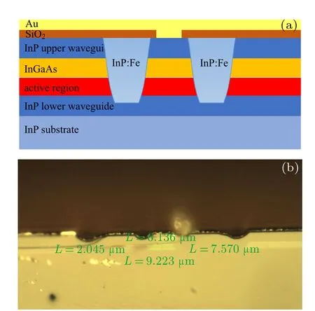
Fig.1.(a)Schematic two-dimensional representation of the device G709.(b)The structure of G709 under a high-power optical microscope.
The epi-wafer was etched into a double-channel waveguide laser. First a 300 nm thick SiO2layer was deposited by plasma enhanced chemical vapor deposition (PECVD) as a mask for filling semi-insulating InP:Fe for better heat dissipation around the ridge. And a 450 nm thick SiO2layer was deposited for insulation, and electrical contact was provided by a Ti/Au layer deposited by electron beam evaporation. An additional 4 µm thick gold layer was electroplated to further improve the heat dissipation. After thinning down to about 140µm,a Ge/Au/Ni/Au metal contact layer was deposited on the substrate side of the wafer. The waveguides were cleaved into 6-mm-long bars, and the facet of sample G709 was uncoated for the measurement of edging emitting power. Finally, the lasers were mounted epilayer side-down on a diamond heat-sink with indium solder,which were subsequently soldered on copper heat sinks.
3. Analysis of experimental results and model establishment verification
The lasers were tested after wire bonding,and mounting on a holder containing a thermoelectric cooler(TEC)to monitor the heat-sink temperature. The measurements were performed using a Fourier transform infrared(FTIR)spectrometer with 0.125 cm−1resolution in rapid scan mode.The output optical power was collected by a calibrated thermopile detector,which was put in front of the laser front facet without any efficiency correction.
3.1. Analysis of experimental results
Figure 2 shows the typical power-current(P-I)curves of sample G709, with 6 to 14 µs current pulses at a repetition rate of 50 kHz and the heat-sink temperature 25◦C. During the test interval, to avoid damage, the lasers were not tested to the maximum operating current in this configuration. Its maximum output power exceeded 704 mW (on double facet)over a broad range of current,and the results of threshold current and dynamic range are similar. Additionally, the continuous wave(CW)light-current-voltage(L-I-V)curves of the sample G709 at the heat-sink temperature 25◦C are shown.Within the tested current range, the working voltage range was 6.543 V-11.054 V and its maximum double output power reached 854.2 mW.

Fig.2. Typical power-current curves of sample G709,with 14µs current pulses at a repetition rate of 50 kHz and the heat-sink temperature 25 ◦C.It also shows the CW light-current-voltage curves of the sample G709 at the heat-sink temperature 25 ◦C.
Figure 3(a) shows the far-field patterns of the device at 25◦C along the ridge-width direction at different injection current. The far-field at 0.5 A exhibits a Gaussian-like distribution.As the current increases from 0.6 A to 0.9 A,the shoulder peaks distributed on both sides in the far field not only gradually enhance,but also irregularly deflect to the left and right directions. Especially in the range of 1.0 A-1.2 A, the farfield peak position undergoes a significant turning, known as the beam steering.[6]It should be noted that the maximum intensity peak of the beam in the far field is offset by+14.2◦and−14.2◦from the facet normal(0◦)at 1.0 A and 1.2 A,respectively. The facet normal(0◦)is used as the zero coordinate of the far-field.The diffraction limit(DL)angle of the fundamental mode at the full-width at half-maximum (FWHM) is 46◦according to the single-slit diffraction theory. In the entire test interval, the FWHM increases from 47◦±0.5◦(≈1.02 DL)at 0.5 A to 60◦±0.5◦(≈1.3 DL)at 1.2 A.Therefore,the farfield at high current could not be a pure fundamental transverse mode. Then perhaps the reason for this beam steering is that the two lowest transverse modes with slightly different effective refractive indexes are coherent, and the phase difference between the modes is constant. Furthermore,varying the current induces substantial angular steering of the output, which is usually accompanied by a significant qualitative change in the spectral characteristics.[6,10]
Figure 3(b) shows that the range of the spectrum gradually broadens from 0.031 µm at 0.5 A to 0.146 µm at 0.9 A.However, the longitudinal mode range of the spectrum suddenly decreases in the range of 1.0 A-1.2 A.It is possible that the increase of the current causes the gain hole-burning effect.Additionally,the spectrum of 1.0 A shows that although a significant small range of widening and multiple longitudinal modes exist around 4.72 µm, it also can be clearly observed that there are a series of relatively small and uniform longitudinal modes in the 4.65 µm-4.70 µm range. Nevertheless,when the laser is energized at 1.1 A and 1.2 A, the optical intensities of the multi-longitudinal mode distributed in this spectrum range are minimal caused by obvious hole-burning in the gain space.
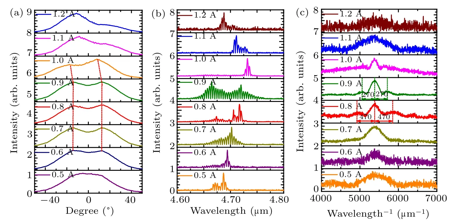
Fig.3. (a)Measured far-field intensity distributions of the device at driving currents of 0.5,0.6,0.7,0.8,0.9,1.0,1.1,and 1.2 A(from bottom to top)in pulsed mode at the heat-sink temperature 25 ◦C.(b)Emission spectra for the λ =4.65µm QCL at T =25 ◦C.(c)Fourier transforms of the spectra. The laser is driven by pulsed current from 0.5 A to 1.2 A at a repetition rate of 50 kHz. The pulse duration is 10µs.
In order to further verify that the beam steering may be caused by the coherence of the two transverse modes. We performed Fourier transform of the spectra. Figure 3(c) shows that there are two situations in the Fourier analysis over a broad range of injection currents, either only showing one peak at a certain current, or showing three closely adjacent and equally spaced peaks.[12]And there is no observation of multiple peaks that are closely adjacent and spaced differently at a certain current. This shows no incoherence between transverse modes in this range.[6,12]At the same time,the far-field profiles under most currents[Fig.3(a)]obviously do not show a completely consistent Gaussian distribution, indicating that these far-fields at high current should not be a pure fundamental transverse mode. Furthermore, since most of the farfields FWHM are between once the DL and twice the DL in the 0.5 A-1.2 A interval, it cannot be considered that these far-fields only contain the first-order mode. As a result, it is natural to attribute them to that the two lateral lowest modes with slightly different effective refractive indices are coherent.This demonstrates the phase locking of the two lowest modes to judge the occurrence of the beam steering.
Finally,COMSOL simulations and theoretical model calculations are performed to further verify the rationality of the judgement and experimental results.
3.2. Model establishment and verification
The modes are simulated by solving the Maxwell’s equations with a 2D finite-element method software. According to the simulation, the two lowest transverse modes can coexist in the laser cavity, as shown in Fig.4(a), where the TM0 and TM1 modes are represented in the bottom panel and top panel,respectively.
It is noted that the stripe width for the double-channel devices typically varies from 6.1µm at the top of the active region to 9.2µm at the bottom,while for the buried heterostructure the average waveguide width is 7.5µm. The reason why high-order modes appear in such a narrow ridge is that the thinner waveguide layer on the active area of the device causes plasmon loss. Therefore,it is very effective to produce a high beam quality by appropriately increasing the thickness of the top waveguide layer and relatively reducing the ridge width.On the basis of the results, figure 4(b) shows the calculated far-field profiles by taking various phase difference(−0.6π to 0.6π) between the basic 0th lateral mode and the 1st lateral mode.

Fig.4. (a) Calculated 2D optical mode distribution for the quantum cascade laser, 0th lateral mode (top panel) and 1st lateral mode (bottom panel). (b) Theoretical far-field profiles for a 7.5-µm-wide QCL emitting at 4.65µm,for a series of phase differences(Φ)ranging from−0.6π to 0.6π. The ratio of photon densities in the two lowest order modes is assumed to be P0/P1=3:4.
From a 2D effective-index model,we assume that the ratio of the photon density of the fundamental mode to the firstorder mode is P0/P1=3:4. The optical field of the whole superposition is approximately[6,15-17]

where β0and β1represent the propagation constants of the fundamental and first-order modes,respectively. The relationship between the two coefficients simulated in COMSOL is β0−β1≈0.031k0,where k0=2π/λ. E0and E1represent the near fields of the fundamental mode and the first-order mode,which can be obtained from COMSOL.
Therefore, if we assume that the aligned phase is at the back facet(phase difference=0),[6]then the phase difference between the two on the cavity surface can be calculated according to the following formula:
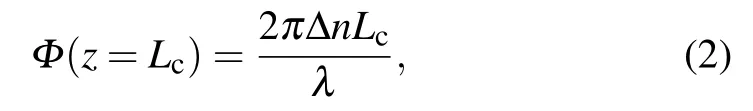
where Δn is the difference between the effective refractive indices of the two near-field modes,Lcis the cavity length of the laser,and λ is the wavelength of the laser. Through this calculation is ideal,the initial far-field experimental result at 0.6 A is consistent with the theoretical calculation of Φ =0, indicating that there is no constant phase in the two modes at the beginning. By this method,we estimate that the phase difference between the two lateral modes is around 0.2π at 1.0 A or−0.2π at 1.1 A,and that the calculated far field profile beam steering angle is around 13.5◦or −13.5◦, which fairly well agrees with the experimental value of 14.2◦or −14.2◦.
3.3. Conclusion and perspectives
In summary,we explain the intrinsic linkage between the spectral instabilities and the beam steering and report a valuable criterion consisting of the analysis of the Fourier transform of the spectra and beam quality to judge the phase difference locking of two modes. Furthermore,our model for 2D interference between the two lowest order lateral modes reproduces the experimental finding. That is,a given device can switch between strong steering in either direction or no steering when the operating conditions(phase difference)are varied.This sufficiently verifies that the criterion of beam steering given in this paper is extremely effective.
Acknowledgment
The authors would like to thank Ping Liang and Ying Hu for their help in device processing.
猜你喜欢
杂志排行
Chinese Physics B的其它文章
- Transport property of inhomogeneous strained graphene∗
- Multi-scale molecular dynamics simulations and applications on mechanosensitive proteins of integrins∗
- Enhanced spin-orbit torque efficiency in Pt100−xNix alloy based magnetic bilayer∗
- Soliton interactions and asymptotic state analysis in a discrete nonlocal nonlinear self-dual network equation of reverse-space type∗
- Discontinuous event-trigger scheme for global stabilization of state-dependent switching neural networks with communication delay∗
- Model predictive inverse method for recovering boundary conditions of two-dimensional ablation∗