Coupling model of AC filter branch in SF6 circuit breaker during the break process
2020-12-02ZaixingPENG彭在兴KaiLIU刘凯YanweiNAN南岩玮SongWANG
Zaixing PENG(彭在兴),Kai LIU(刘凯),Yanwei NAN(南岩玮),Song WANG
(王颂)1, Fei YANG (杨飞)2, Hao SUN (孙昊)2 and Yuan LA (喇元)3
1 Electric Power Research Institute,China Southern Power Grid,Guangzhou 510080,People’s Republic of China
2 State Key Laboratory of Electrical Insulation and Power Equipment,Xi’an 710049,People’s Republic of China
3 China Southern Power Grid, Guangzhou 510080, People’s Republic of China
Abstract
Keywords: AC filter branch, arc characteristics, SF6 circuit breaker
1.Introduction
AC harmonic filter branches are usually equipped in the AC side of HVDC converter station to eliminate the harmonic waves and generate the reactive power.Considering the operating status of system, the filter branch needs to operate frequently to keep the balance of reactive power in the converter station [1].SF6circuit breaker is an important switching device for AC filters,and its performance is of great significance to the reliability of DC power supply.The use of a large number of power electronics in HVDC transmission generates high-order harmonics on both the AC and DC sides,which seriously affect the interruption of the circuit breaker in AC filter.There have been several reports about the interruption failure of SF6circuit breaker due to the breakdown during the breaking process in the high voltage AC filter circuit, which could cause the accident like the explosion in the converter station[2-5].Thus,it is necessary to investigate the arc extinguish process considering harmonic current in the high voltage AC filter circuit.
In recent years,research on AC filter circuit breakers has focused on the establishment of high-frequency arc models and the calculation of fast transient overvoltage.By dividing the arc burning phase and arc decay phase, Wang et al has proposed a dynamic arc model based on the principle of highfrequency arc extinguishing [6].The influence of the timedependent arc resistance on the arc modeling was researched.Fang et al calculated the recovery voltage of the AC filter breaker in UHV converter station [7].The result showed that the opening of the AC filter circuit breaker would cause the high-frequency oscillation in the recovery voltage, which is different from the normal capacitive breaking.However, the arc models above were mainly based on the black-box models and thus the accuracy when describing the real situation at high-order harmonic conditions should be carefully checked.
Much research on the high voltage SF6circuit breaker has been done in recent years.Fang et al [8] researched the dynamic characteristics of the SF6nozzle arc before and during current-zero period based on the Prandtl mixed-length turbulence model, which proved that the turbulence has important influence on the current-zero behavior and thermal recovery process.Liu et al [9] adopted the k-ε turbulence model to simulate the arc plasma in the case of short-circuit breaking of a 500 kV SF6circuit breaker.Zhang et al [10]studied the SF6arc considering the ablation of PTFE nozzle.The simulation and experiment of the self-blast circuit breaker showed that the energy carried into the chamber by the PTFE vapor is important for the pressure increment.To overcome the problem that the NEC radiation model cannot effectively estimate the radiation reabsorption,Fang et al[11]established a semi-empirical model, which divides the arc column into a net radiation zone and a reabsorption zone.However, few researchers studied the influence of high-order harmonic current on the arcing process.
In this work,a coupling model of AC filter branch circuit and the arc plasma in the circuit breaker has been built to research the arc extinguishing process under high-order harmonic current.The arc plasma at power frequency (50 Hz),power frequency combining with the 11th harmonic and power frequency combining with the 24th harmonic current was computed considering the influence of the arc resistance on the external circuit.
2.Modeling of the arc plasma
2.1.The governing equations of arc plasma
To simplify the analysis, the numerical simulation followed the assumptions below.(1) The arc plasma is in local thermodynamic equilibrium condition; (2) the arc plasma is axisymmetric;(3)the electron emission and ion bombardment on the electrode surface were neglected;(4)the electrode erosion and the nozzle ablation were neglected.
The MHD model which contains the fluid equations and electromagnetic equations was adopted.The governing equations are shown in equations (1)-(8):


whereρ:mass density,t:time,u: gas flow velocity,p:pressure,μ0:magnetic permeability, ∇: Lagrange derivative,τ:stress tensor,j:current density,B:magnetic flux density,E:energy,kef:thermal conductivity,σ: electrical conductivity,E: electrical field,Prad:radiation loss,φ: electrical potential,A: component of the magnetic vector potential.
The thermodynamic and transport properties of SF6used in equations (1)-(4) at different temperatures and pressures were obtained from the Chen’s work [12].The net emission model as in Fang’s work [6] was used to calculate the radiation loss.For the turbulence,the two-equation turbulence model allows the determination of turbulent length and time scale by solving two separate transport equations.For the k-ε model, it is related to the time-averaged turbulent kinetic energy,k,and dissipation rate ε[4],which are determined by:
where the kinematic viscosityvtcan be calculated as
Since the peak value of the arc current in this work is about 300 A, according to Yan’s research, the following turbulent parameters were used.The constants in equations(9)-(11) were set asc1e=1.44,c2e=1.92,σk=1.0,σε=1.3,cμ=0.09 [13].
在诸城市南部山区的康岭山上,占地1.2万亩的榛子林让原本光秃秃的山头,如今变成了树的海洋。“俺每天都来转转,看着这些满山成片的绿色,人就变得更有干劲儿。”64岁的魏本欣是这一片榛子林的主人,他将周边村落的山岭薄地流转过来,荒山造林,还带动百姓脱贫致富。
2.2.Calculation domain and boundary conditions
In order to reduce the computational expense,the geometry of a certain AC filter breaker was reasonably simplified,as shown in figure 1, which contained electrode, hollow electrode, cylinders,nozzle and fluids in the calculation domain.The boundary where Z=0 m was set as the axis.The cylinder and the electrode were moved towards the right at a constant speed of 12 m s−1.The grid inside the dotted frame of figure 1 is shown in figure 2.
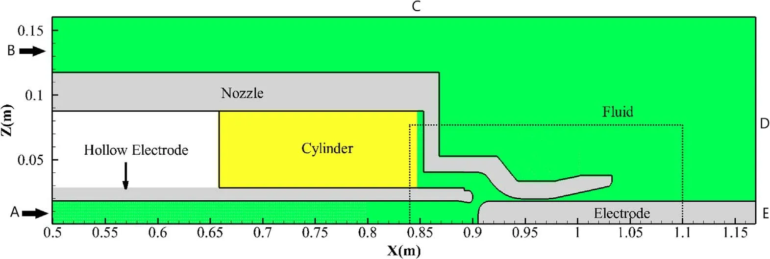
Figure 1.Calculation domain of arc plasma (The grid inside the dotted frame is shown in figure 2).
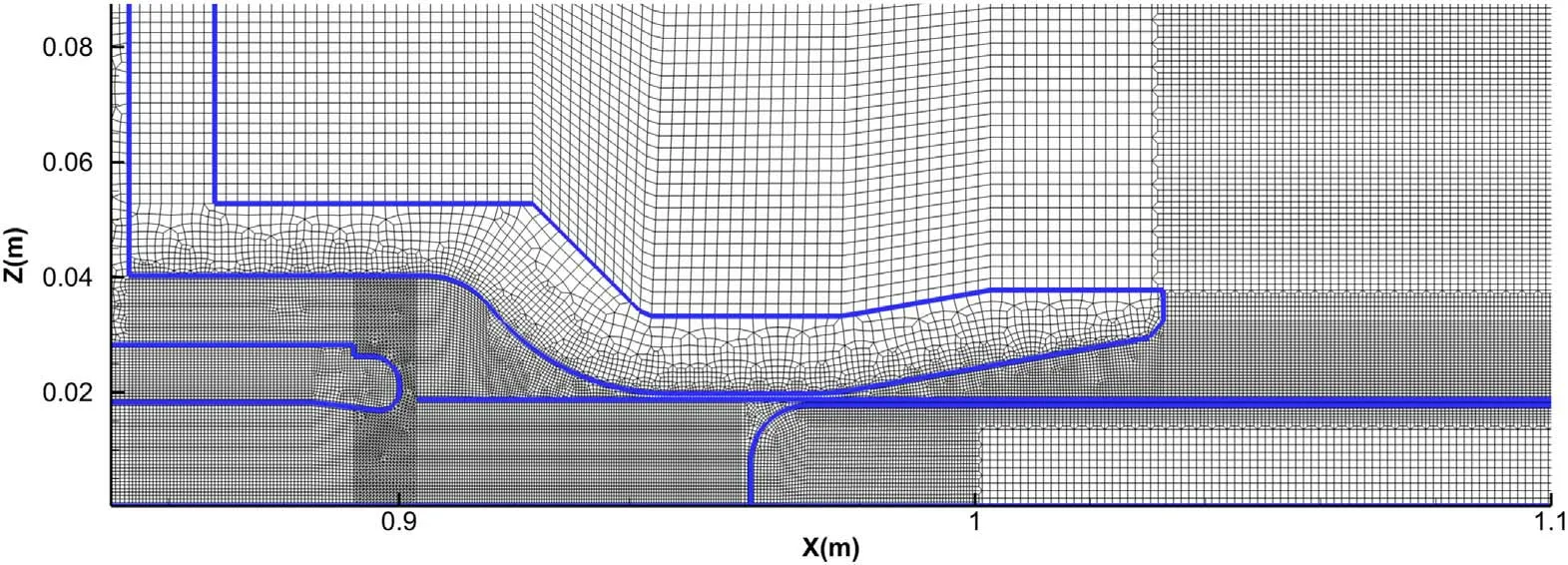
Figure 2.Part of the calculation domain.
The initial pressure was set as 6×10⁵Pa, while the boundaries A,B,C and D were set as the pressure outlet with a constant pressure of 6×10⁵Pa and a constant temperature of 300 K.The electric potential of the hollow electrode was set as zero.Since the current was mainly 50 Hz in the simulation,the skin effect would not have a significant effect on the current distribution in the electrode,so the distribution of current density would not affect the calculation of arc plasma.In order to simplify the calculation of the electromagnetic field, the current density was evenly distributed on the cross-section E.Other boundaries such as A, B, C and D were set as Neumann boundary conditions, i.e.the current density was zero.
3.Modeling of the AC filter branch circuit
3.1.The setting of AC filter branch circuit
In the HVDC converter station, 3-4 groups of AC filters are generally used in parallel connecting the AC bus to form a large group of filters.In this paper,to simplify the calculation,only a single group filter branch was considered,as shown in figure 3, which is a double-tuned filter branch in a 550 kV HVDC converter station.The parameters of the capacitors,inductors and resistors are shown in table 1.The current at the power frequency (50 Hz) is determined by the grid-side voltage, while the high-order harmonic current is generated by the other components in the converter station.In this paper, the high-order harmonic current was generated by a harmonic voltage source.The circuit breaker was in parallel to the voltage dividing capacitor as the Rarc1 and Rarc2 in figure 3.
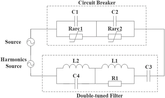
Figure 3.AC filter branch circuit.
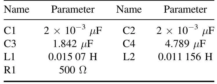
Table 1.Parameters of the AC filter branch.
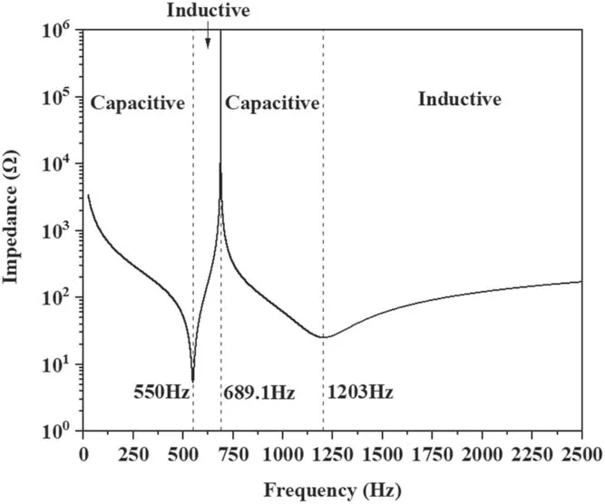
Figure 4.Equivalent impedance of AC filter versus frequency.
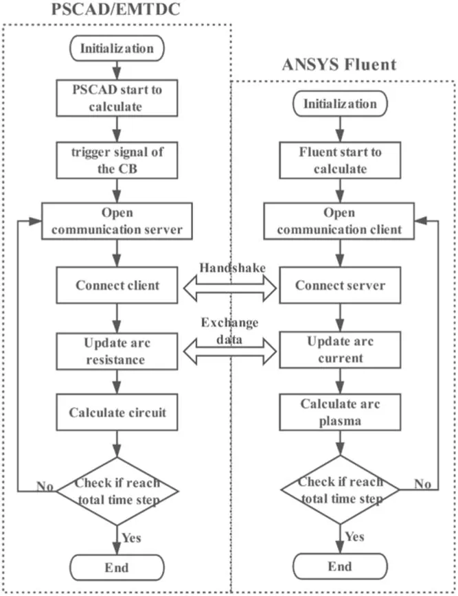
Figure 5.Flow chart of the coupling of arc with external circuit.
The equivalent impedance of the filter versus frequency is shown in figure 4, which would reach the lowest value at about 550 Hz and 1203 Hz.Thus, the filter branch is mainly used to filter the harmonics current of 550 and 1200 Hz.Besides, the equivalent impedance of the filter branch at 50 Hz is 0.045−j1722.526 Ω.So, the branch could provide reactive power to maintain the stability of voltage.The voltage source was set to the bus’s voltage to simulate the infinite bus power.The harmonics source was set to a specific frequency and amplitude to simulate the harmonics through the AC filter branch in the HVDC converter station.
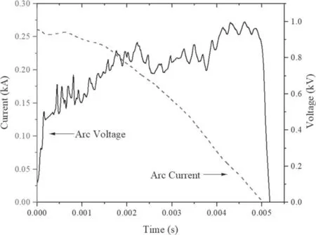
Figure 6.Arc current and voltage at 50 Hz current.
The relationship between the SF6arc model and AC filter branch can be seen in figure 3.The SF6circuit breaker studied in this paper contains two arc chambers, which are represented by two resistors Rarc1 and Rarc2 in the AC filter branch circuit, as shown in figure 3.This work does not consider the difference between the two arc chambers, so the values of Rarc1 and Rarc2 were set to be the same to simplify calculation.The capacitors C1 and C2 are the stray capacitance of the arc chambers.The stray capacitance between the porcelain shell and the ground was neglected due to its small value.The behaviors of arc plasma would cause the transient process in the circuit.Therefore, it is necessary to couple the circuit with the arc plasma.In this paper,the AC filter branch circuit was calculated by PSCAD/EMTDC, which will be discussed in detail in next section.
3.2.Coupling of arc with AC filter branch circuit
The flow chart of the coupling is shown in figure 5.The named pipe, which is a convenient inter-process communication mechanism, was used to exchange the data between the ANSYS Fluent and PSCAD/EMTDC to achieve this coupling.During the arcing process, the time steps of PSCAD and Fluent were set as the same to ensure the consistent coupling.The arc resistance was computed as arc voltage divided by arc current.After that, the resistance calculated by Fluent and the current value by PSCAD would be exchanged with each other as in figure 5:when the arc resistance in the circuit was updated by arc simulation in Fluent, a new state of circuit would be computed in next time step; after the PSCAD obtained the current values, the boundary condition of current in arc plasma(boundary E in figure 1)calculation would be updated and then a new arc state was computed.The iteration would continue until the calculation reached the total time step for arcing process.After the current drops to zero,the calculation of the Fluent was suspended and only the solution by PSCAD was used to obtain the recovery voltage.
Figure 7.Temperature distribution at only 50 Hz current.
4.Results
In order to study the influence of harmonics on the arc plasma,based on the circuit in figure 2,the arc extinguishing processes at power frequency (50 Hz) current and power frequency current combined with high-order harmonics were researched.Since the circuit in figure 2 had the lowest impedance at the 11th harmonic(550 Hz) and the 24th harmonic (1200 Hz), the harmonic currents at these two frequencies were chosen to investigate the interactions between arc plasma and circuit.
4.1.Power frequency current situation
In order to verify the model and make comparisons among different harmonics, first the arc extinguishing at power frequency current was calculated,in which the amplitude of voltage source was set as 450 kV, the frequency was set as 50 Hz, and the arc ignition was at the peak of the current (about 261 A).The waveforms of arc current and the arc voltage are shown in figure 6.The arc resistance makes the current oscillate slightly.The arc voltage generally keeps increasing from 0 to 2.5 ms,which was mainly due to the increase in arc length caused by the continuous separation of the two electrodes.As the input energy increases,the increasing rate of arc resistance begins to decrease,while the arc voltage is stabilized at around 0.8 kV from 2.5 to 4 ms.When the arc current drops to 75 A at 4 ms,the arc voltage rapidly increases to 1 kV.Finally, at 5.12 ms the current drops to zero.
The temperature distributions at different moments are shown in figure 7.The arc temperature drops after 3 ms due to the decrease of input power and strong cooling by the gas flow.The arc radius is defined as the zone from the arc core at the axis to the area where the temperature is 4000 K.It is quite obvious that at 5 ms the arc radius decreases significantly compared to 4 ms.
Figure 8.Arc current and voltage at 50 Hz combining with 15%550 Hz current.
4.2.Power frequency combining the 11th harmonic current
A simplified breaking process at power frequency combining 15% of the 11th harmonic current was calculated to research the arc plasma in AC filter circuit breaker.The main voltage source was the same as that in section 4.1, which has an amplitude of 450 kV,because it depends on the power system and does not change with the amplitude or the frequency of the harmonic current.The amplitude of the 11th harmonic voltage source was set as 0.21 kV in order to get the harmonic current with 40 A amplitude, where the impedance of AC filter branch was 5.36 Ω at 550 Hz.The initial phase of the harmonic voltage was set as zero.The waveforms are shown in figure 8 while the temperature distributions are shown in figure 9.The arc voltage appeared to fluctuate with current from 2 to 4 ms.After that, the current dropped from about 100 A to zero within 0.8 ms, while the arc voltage increased from 0.85 kV at 4 ms to 0.99 kV at 4.14 ms and then dropped to zero.

Figure 9.Temperature distribution at 50 Hz combining with 15% 550 Hz current.
4.3.Power frequency combining the 24th harmonic current
A simplified breaking process at power frequency combining with 15% of the 24th harmonic current was calculated to research the arc plasma in AC filter circuit breaker.As mentioned in section 4.2, the voltage source with power frequency was the same as the non-harmonic case.The impedance of AC filter branch was 25.139 Ω at 1200 Hz, so the amplitude of the 24th harmonic voltage source was set as 1 kV in order to get the current with 40 A amplitude.The initial phase of the harmonic voltage was also set to zero.The waveforms are shown in figure 10 while the temperature distributions are shown in figure 11.The arc voltage increases sharply at the initial moment.From 0.2 to 1.2 ms, although the arc current fluctuated continuously, the arc voltage keeps increasing.At 3 ms,the arc voltage is stabilized.After 3.5 ms,when the arc current is low and the arc enters the nozzle area,the arc radius decreases obviously due to the gas-blasting,making the arc voltage rise rapidly.At 4.27 ms, the current reached the last peak before current-zero, which was about 80 A.At the same time, the voltage is about 1 kV, after that both the current and voltage dropped rapidly to zero.
5.Discussion
5.1.The effect of harmonic current on the arc
Combined with high-order harmonic current, the arc current will decrease faster during the current zero, which could significantly influence the dielectric recovery of the residual hot gas.The temperature distributions at current-zero for both non-harmonic and harmonic conditions are shown in figure 12.With a high-order harmonic current of 40 A amplitude, since the decreasing rates of the current are 125 A ms−1and 352 A ms−1, with the 11th and 24th harmonics, respectively, which are much higher than the power frequency current (68 A ms−1), the arc temperature at highorder harmonic current during the current zero period is much higher than that at power frequency.Additionally, the arc radius at high-order harmonic current is much wider and the temperature at the axis is higher, compared to the results at power frequency.Therefore, the dielectric recovery of the residual hot gas at high-order harmonic current is more difficult than the case at power frequency.More importantly, in the case of high-order harmonic current,the current zero point appears earlier,which could further increase the difficulty for the arc extinguishing.Comparing the cases between the 11th and 24th harmonic current, the results of arc radius seem similar but the temperature at the 24th harmonic current is generally higher.
Figure 11.Temperature distribution at 50 Hz combining with 15% 1200 Hz current.
Figure 12.Temperature distributions at current zero period of different cases.
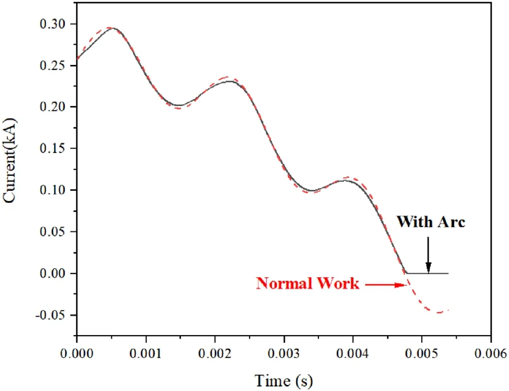
Figure 13.The AC filter current at the breaking process and the normal operating condition.
5.2.The effect of the arc plasma on the external circuit
For the AC filter circuit breaker, since the filter branch has a relatively low impedance to the specific frequency harmonics,the influence of the arc plasma on the harmonic current cannot be neglected.Figure 13 shows the influence of the arc on the external circuit at power frequency combining with 15% of the 11th harmonic current.Comparing the result at breaking process with that at the normal operating condition, the maximum difference of arc current can reach 7.5 A, which is 40% amplitude of the harmonic current.If the amplitude or the frequency of the harmonic current is further changed,there could be more differences on the values of the current.Therefore, since the arc current in these cases cannot be predicted directly if the circuit breaker is considered to be an ideal breaker,the coupling of the arc with the AC filter branch circuit is quite necessary in the numerical modeling of the circuit breaker in the AC filter branch at the HVDC converter station.
6.Conclusion
With the calculation of the coupling model between AC filter branch circuit and arc plasma in the circuit breaker, the following conclusions can be obtained:
(1) The high-order harmonic current of AC filter branch would significantly increase the decreasing rate of current (di/dt) during the current zero compared to the situation of power frequency current, which gives less time for the temperature decaying and makes the temperature at the current zero higher.For example, if a 1200 Hz harmonic current with an amplitude of 15%is added, the highest temperature at the current zero could increase from 5000 to 9000 K, and the high temperature area would be wider.This trend will be more distinct if the frequency is higher, indicating the worse dielectric recovery as the di/dt increases, which should be noticed for the industrial purposes.
(2) Different from the situation in the case of power frequency, the influence of the arc resistance on the interruption current cannot be neglected.For example,if a 550 Hz harmonic current with an amplitude of 15%is added,the difference on the current caused by the arc resistance could reach 7.5 A compared with the operating condition without arc, which is nearly 40%of the harmonic amplitude.The results indicate the necessity to consider the arc resistance during the interruption of the harmonic current.
By coupling the AC filter branch circuit with the arc plasma in the circuit breaker,many new results and trends can be obtained.Still, to verify the calculation and make the numerical model more universal for industrial applications,large amount of test results should be used in future.
Acknowledgments
This work was supported by the Major Science and Technology Project of China Southern Power Grid Co., Ltd(ZBKJXM20170065): Research on Harmonic Resonance Mechanism, Suppression Measures and Impact on Main Equipment of AC/DC Hybrid Power Grid.
猜你喜欢
杂志排行

Plasma Science and Technology的其它文章
- The structure of an electronegative magnetized plasma sheath with non-extensive electron distribution
- The effect of forced oscillations on the kinetics of wave drift in an inhomogeneous plasma
- Numerical simulation of impact of supersonic molecular beam injection on edge localized modes
- Effect of background fluctuation on velocity diagnostics by Mach probe
- Mitigation of blackout problem for reentry vehicle in traveling magnetic field with induced current
- New method for rekindling the explosive waves in Maxwellian space plasmas