Mitigation of blackout problem for reentry vehicle in traveling magnetic field with induced current
2020-12-02ShaoshuaiGUO郭韶帅KaiXIE谢楷BinSUN孙斌andShaoweiLIU刘少伟
Shaoshuai GUO (郭韶帅) , Kai XIE (谢楷), Bin SUN (孙斌) and Shaowei LIU (刘少伟)
School of Aerospace Science and Technology, Xidian University, Xi’an 710071, People’s Republic of China
Abstract
Keywords: blackout, traveling magnetic field, self-induced current, traveling magnetic field velocity
1.Introduction
A high-speed spacecraft passing through Earth’s atmosphere at an altitude between 20 and 100 km forms a shock wave in which a plasma sheath is formed with an electron density of about 1015-1019m−3[1].Any electromagnetic(EM)wave transmitted through this plasma is attenuated,reflected or absorbed,causing breaks in terrestrial and spacecraft telemetry, control, and other communication links.The phenomenon is known as radio blackout [2-6].To achieve uninterrupted monitoring of spacecraft reentries, researchers have proposed and tested a series of methods to mitigate blackout [7-11], including aerodynamic shaping, electrophilic injection or ablation, magnetic windows,high-frequency transmissions and inflatable reentry aeroshell surface catalysis effects.One of the more promising methods is the magnetic window.When a magnetic field is present, free electrons twirl around the magnetic field lines at cyclotron frequencies ωb=eB/me.With increasing magnetic field strength,the electron radius (or gyro-radius) rg=mv/eB decreases.At sufficiently large magnetic field strength,the free electrons in the plasma sheath are tightly bound to the magnetic field lines.The free electrons interact with difficulty with the electric field component of the EM wave,thereby creating a window for wave propagation[12,13].Rawhouser calculated that a 1.3 T magnetic field was needed to eliminate S-band blackouts[14].Starkey et al have also worked on telemetry attenuation in a plasma sheath and revealed that a 1.0 T magnetic field sustains a radio-wave-propagating plasma [15].The strong magnetic fields required for such magnetic windows are costly and very difficult to generate under practical flight conditions.Whether using permanent magnets, electromagnets or even superconducting magnets, the size and weight of these magnets far exceed the load capacity of the aircraft.The technical specifications for reentry vehicles are extremely difficult to achieve[15].Clearly,reducing the required strength of the magnetic field in a magnetic window is important.
One of the ways to reduce the field strength is the E×B method [16-19].In this method, both electric and magnetic fields are applied perpendicularly to each other.In this way,these applied fields give rise to an E×B drift,which accelerates the plasma away from the antenna window.Kim et al put forward a magnetohydrodynamic(MHD)model and experiment to analyze the required field strength needed to reduce the electron density in this E×B method [16].The experimental results indicated that the attenuation of electron density reached 70%-75% at 10 mm above the electrode, and the required magnetic field strength was reduced from 1 T to 0.2 T.
In the E×B method,both fields are static,the two fields being generated between a pair of electrodes and an electromagnet under constant excitation.Recently, Zhou et al replaced the static magnetic field with a spatiotemporal changing magnetic field,proposing a traveling magnetic field(TMF) to reduce the required strength of the magnetic field[20].The TMF is a composite magnetic field, which is generated by injecting a three-phase symmetrical excitation current in a magnetic field generator.In the TMF method, the electrons and ions are driven away from the antenna window by the EM force J×B,which is generated by the interaction between the current in the plasma and the spatiotemporally changing magnetic field.The current density J is an important parameter governing the EM force that determines the reduction in plasma density.Based on a proposed computational model [18], the results show that plasma electron density is reduced by about two orders of magnitude when the current density J=200 A m−2,the magnetic field strength is as low as 0.15 T, and the traveling velocity of the magnetic field is Vw=1000 m s−1.However, certain limitations exist within this method [20].One deficiency is that the current density J (which is assumed to be J=200 A m−2in [20])requires electrodes to be inserted into a high-temperature gas flow.For actual reentry vehicles, technical obstacles arise.In this paper, we propose an alternative means-spatiotemporal changes of the TMF itself can generate an induced current inside the conductive plasma layers.If the velocity of the TMF is sufficiently large, the self-induced current may reach a level that suppresses signal blackout, thereby eliminating the need for external injected currents.A model for this selfinduced current induced by the TMF in plasma was developed, and reductions of the electron density were simulated for comparison with the TMF method of injecting current.
The remainder of the paper is organized as follows:analytical expressions of the plasma density reduction ratio for a TMF of self-induced current are derived in section 2.Simulations of the effect of the TMF on electron density are conducted in section 3.The EM wave propagation in the TMF region is introduced in section 4.Model verifications are conducted in section 5.Discussion and conclusions of this paper are presented in sections 6 and 7, respectively.
2.Analytical expression of TMF acting on plasma flow
In the TMF method,both current density J and magnetic field B determine the driving force.Previously,in the TMF method[20],the current density J was increased by injecting current into the plasma fluid.In fact, spatiotemporal changes in the TMF itself can generate an induced current inside the conductive plasma layers.In this method, the TMF is a composite magnetic field,which is generated by injecting a three-phase symmetrical excitation current into a magnetic-field-generating device.By altering the excitation current of each phase or its phase shift,adjustment of the travelling magnetic field can be achieved[21].A schematic diagram of the application of the TMF is shown in figure 1(a).The phase shift between adjacent coils is °120 , so that the amplitudes of the resulting radial magnetic field components in the plasma approximately behave as continuous magnetic waves with a wavelength ofλ=6d.The TMF velocityVw=λfcan be changed by changing the frequency of the exciting current.The direction of the feeding current can be reversed,thus giving rise to a left- or right-directed action of the TMF.
In this method, the reference frame is fixed on the aircraft.As a simple idealized model of the TMF showing proof of principle(figure 1(b)),the TMF travels along the x direction with speed Vw.The plasma fluid enters the magnetic field along the negative x direction at speed V0.When the plasma fluid nears the origin, the magnetic field begins to act upon the fluid, in which the fluid velocity is V(along the negative x direction).We select the following form of the vector potential A of the applied magnetic field:

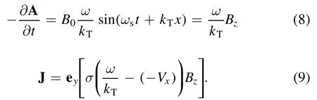
where eyis the unit vector of the coordinate axis,B0is the peak value of TMF,ωsis the frequency of the applied field,and kTis the wave number of the TMF.This form fulfills the Coulomb gauge condition:

In free space, we have from magnetostatics:

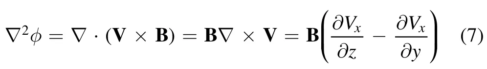
With equations(1)and(3),assuming the magnetic field has only longitudinal components Bz, we obtain the associated magnetic field:


Figure 1.Schematic of the applied TMF method.(a) Configuration of the TMF, (b) simple idealized model of the TMF, (c) generation principle of induction current, (d) principle of TMF-driven plasma.
The induced current and the principle of the TMF-driven plasma are shown in figures 1(c) and (d), respectively.The induced electric current density in the plasma fluid can be written as

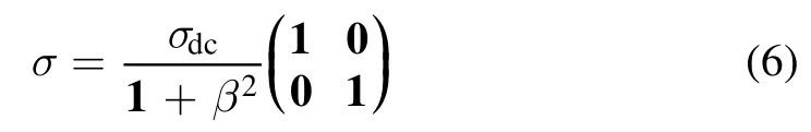
where the electric field is expressed through the electrostatic and vector potential.V is the fluid velocity, and σ is the plasma conductivity and is a tensor with magnetic field [16].
In equation (5) we approximate A and B by the applied fields and for the electrostatic potential in equation (5) we obtain:
With equations (4)-(5) and (7), we produce an induced current density J of
This current density, in turn, produces a force density J ×B (in the x direction), so the Lorentz force entering the Navier-Stokes equations is:

The TMF velocity Vwtakes the form [22, 23]:

where ωsis the angular frequency of the three-phase excitation current,andkT=2π λis the wave number of the TMF.
The following assumptions were made in the study to simplify the model:
(1) The plasma is quasi-neutral near the TMF generator.
(2) Ionization reactions in the TMF region are not considered because the TMF generator is installed in the antenna window,which is usually far away from the stagnation region.The plasma in the TMF region primarily comes from the stagnation region [24].
(3) The ions are cold in hypersonic flow,Ti≈Te[18].The electron temperature in the experimental data of the RAM-C test vehicle ranges from 0.2 to 1 eV [2].
(4) The magnetic field is unidimensional and uniform along the z direction.
(5) The magnetic Reynolds number is a dimensionless parameter in magnetic fluid mechanics defined as the ratio of magnetic field freezing to magnetic field dissipation.Under a low Reynolds number, the effect of magnetic field dissipation is obvious, and the effect of magnetic field freezing can be ignored.In hypersonic flow, the magnetic Reynolds number is smaller than 10−3when the ionization rate is less than 1%[25].With a low magnetic Reynolds number in the plasma, the magnetic field in the plasma is determined mainly by the TMF.
The derivation of the analytical solution of the onedimensional TMF model in the MHD regime is developed below.In this derivation, only the x direction is considered and the magnetic field normal to the axis of motion only has longitudinal components Bz(figure 1(b)).The drag due to ion collisions is ignored to simplify the model.In the onedimensional MHD regime, the conservation equations for mass and momentum are [18]:

where n denotes the plasma number density, Vithe particle velocity,mithe mass of the ion,kBthe Boltzmann’s constant,Tithe ion temperature, Tethe electron temperature, and J the current density.
With equations (10)-(13), the equations of motion for this one-dimensional case are:

Here the plasma velocity is defined as [18]
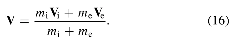
Because the mass of the ions is much heavier than the electron mass, the plasma velocity is nearly the same as the ion velocity, V≈Vi≈Vx.
Then, with equations (14)-(16), we obtain

For the one-dimensional case,nVis a constant from equation (12):

With equation (17), (18) becomes
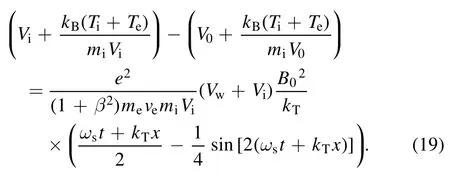
By solving equation (19), the density reduction ratioN(x)=n(x)/ne0representing the ratio of the plasma density with the TMF to the initial plasma density can be calculated from


In equation (20), the plasma density reduction ration,N x,() implies that the smaller the reduction ratio, the lower the electron densityNeTMF(x) after the application of the TMF.Moreover, we see thatB0and the TMF velocity are important determining factors ofN x.() To decreaseN x()while reducing the magnetic field, it is necessary to increase the TMF velocity.
3.Effect of TMF on electron density
On the basis of the proposed model, the plasma parameter settings at 40 km altitude were established to study the effect of the TMF on electron density.The electron densityNeTMF(x) after applying the TMF was obtained with the antenna window length L set at x=0.15 m.In simulations,we considered instanceswhen a maximum magnetic field appears, settingB0=0.15 T, which is the maximum magnetic field at the maximum load of the system[20].During a typical reentry phase of a vehicle(e.g.,RAM-C[1])at a 40 km altitude,experiments have shown that the electron densities near the antenna window are approximately 1017-1018m−3[14], the collision frequency ranges from 1 to 10 GHz, and the electron temperature and ion temperature are approximately 0.2 eV, as given in [2] and[19].The velocity of the vehicle at 40 km is approximately 7400 m s−1, while the plasma velocity is relatively slow compared to the vehicle velocity [17].The plasma velocity ranges from 1000 m s−1to 5000 m s−1, which is taken from the simulation results of [26].The authors will first consider the plasma with various parameters to study the effect of the TMF on electron density.
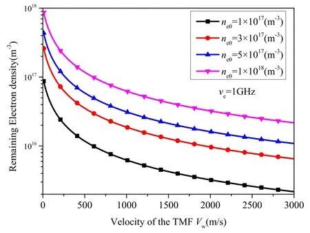
Figure 2.Remaining electron density as a function of TMF velocity with initial plasma electron density ne0 as a parameter, ve=1 GHz,and V0=3000 m s−1.
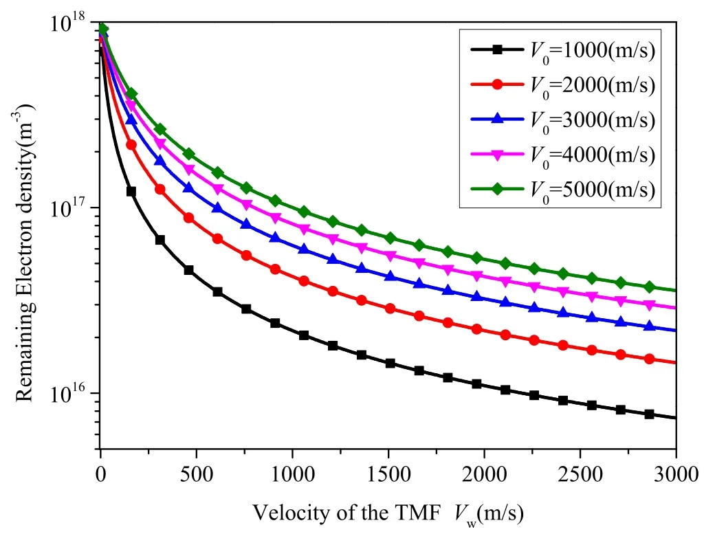
Figure 3.Remaining electron density as a function of TMF velocity with plasma velocity as a parameter, ne0=1×10¹⁸ m−3, and ve=1 GHz.
The effect of the TMF on electron density is shown in figure 2.It can be seen that as the velocity of the TMF increases,the remaining electron density gradually decreases,which means applying a higher velocity of TMF will cause a greater plasma density reduction effect.It is also found thatremains identical at different initial electron densitiesne0(without the TMF effect)with the same velocity of TMF.For example, the density reduction ratio is 0.02 for different electron densities if the velocity of the TMF Vw=3000 m s−1.Therefore, it can be concluded that the methods would work for both high and low plasma electron densities, which would be helpful for mitigating the radio blackout problem.
The initial plasma velocity V0affects the plasma density reduction, as shown in figure 3.The simulation conditions werene0=1×10¹⁸m−3and ve=1 GHz.It is shown that as the initial plasma velocity increases,the effect of the TMF decreases.We also find that a lower initial velocity enables a higher plasma density reduction.
The collision frequency is another parameter that affects plasma density reduction.It follows from figure 4 that the proposed method can still realize at least an order of magnitude of reduction at high collision frequencies with higher TMF velocity.

Figure 4.Remaining electron density as a function of TMF velocity with the collision frequency as a parameter, ne0=1×10¹⁸ m−3,and V0=1000 m s−1.
The reductions in electron density using this method were also simulated for comparison with the method of injected current with the plasma parameter settings at 40 km altitude.The electron densityNeTMFafter the TMF is applied is obtained simultaneously with the following parameters set:plasma flow velocity V0=5000 m s−1, initial electron densityne0=5×10¹⁷m−3and 1×10¹⁸m−3,B0=0.15 T,electron temperature Te=0.2 eV, ion temperature Ti=0.2 eV, and collision frequency ve=1 and 10 GHz [19].In the method of injecting current, a fluid plasma model based on the basic equations of MHD was derived to describe the TMF effects on the plasma;here the electrons and ions in the plasma were subjected to a Lorentz force J×B.The method increases the current density J=200 A m−2following an injection of current into the plasma fluid.In this study, we assume a self-induced current is generated simultaneously by the TMF as the TMF velocity increases.This self-induced current is an alternative source of injected current, thereby eliminating the need for a conductive contact with the hightemperature fluid.Figure 5 shows a comparison of simulation results for the electron densityNeTMF(L) (after the TMF effect) obtained with both ve=1 and 10 GHz from our proposed method and the method of using injected current.

Figure 5.Effect of TMF on electron density.(a) ve=1 GHz, (b)ve=10 GHz.
Regardless of electron density (figure 5(a)), for the proposed method using self-induced current, a reduction ratio of up to an order of magnitude can be achieved without injecting current.WhenB0=0.15 T, the initial electron density (without the TMF effect)ne0=1×10¹⁸m−3, and ve=1 GHz; for example, the electron density is reduced to 1×10¹⁷m−3when the velocity of the TMF Vw=1100 m s−1for the proposed method.As the collision frequency increases, the interaction between particles in the plasma is enhanced, thereby leading to a decrease in conductivity.At the same TMF velocity,the self-induced current is reduced along with the EM force.In figure 5(b), with the collision frequency set to 10 GHz, our proposed method also reduces the electron density by up to an order of magnitude without needing to inject current into the plasma.For example, withne0=1×10¹⁸m−3and ve=10 GHz, the electron density is reduced to 1×10¹⁷m−3when the velocity Vwis approximately 9000 m s−1.Although the required velocity under the higher collision frequency is about eight times that under the lower collision frequency, achieving a high-speed TMF is far easier in engineering than injecting current into plasma.
For example, supposing a TMF generator produces a field wave of wavelength 10 cm, the required excitation current frequency of the TMF generator is only approximately 100 kHz when the velocity is as high as 104m s−1,which can be realized easily using an electronic switch.Moreover, the cut-off frequency of the magnetic cores reaches MHz levels;that is, neither material nor technical obstacles exist to increasing the TMF velocity in engineering implementations[27].Therefore, this TMF method based on self-induced current is feasible in obviating the need for a magnetic field.
4.Propagation properties of EM wave in TMF region
4.1.Attenuation of EM wave propagating through plasma
In this study, the TMF generator generates a sinusoidal magnetic field in the plasma (as shown in figure 1(c)), the magnetic field ranges from 0 toB0,and the applied magnetic field strengthB0is less than 0.15 T, which is the maximum magnetic field at the maximum load of the system [20].The electron cyclotron frequency ranges from 0 to fB0Hz;in order to avoid the resonance absorption phenomenon caused by the similarity between the radio frequency and the electron cyclotron frequency, the applied magnetic field in this paper satisfies that fB0<1/3f.Under the considered conditions,the applied magnetic fields for the L-band (1.575 GHz), S-band(2.3 GHz), C-band (5.7 GHz) and X-band (9.21 GHz) are 0.02 T,0.03 T,0.06 T and 0.1 T,respectively.In this case,the magnetization of the plasma can be neglected since it has little effect on the attenuation of the EM wave.Therefore,the plasma layer can be simplified and configured to function as a nonmagnetic plasma; the relative magnetic permeability may be taken as μr=1 with the complex permittivity of each plasma layer expressed as [28]

whereε0is the permittivity of a vacuum, ω is the angular frequency of the EM wave,is the plasma resonant frequency, andueis the collision frequency,which is constant in each plasma layer.
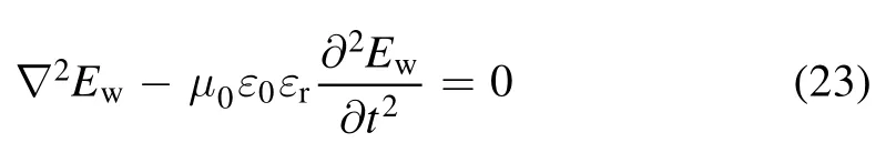
For this study,the incident wave is a transverse magnetic wave propagating along the z-axis (figure 6).The plasma is divided into n layers, with the (n+1)th layer being air; the thickness of each layer is denoted as di.Thus, the Helmholtz equation becomes [29]
whereε0is the permittivity of a vacuum,εris the relative permittivity of plasma,μ0is the permeability of a vacuum,and the electric fieldis given by[19,29]

For the nth layer, the electric fieldand the magnetic fieldcan be described as


Figure 6.Schematic diagram of EM wave propagation in the layered plasma.
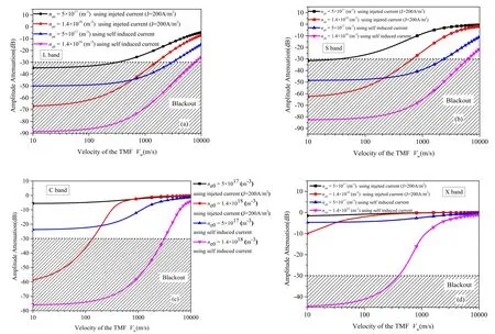
Figure 7.Effect of the TMF on EM wave propagation in plasma.(a) L-band, (b) S-band, (c) C-band, (d) X-band.

Figure 8.Distributions of induced current density with TMF, ne0=1×10¹⁸ m−3, ve=1 GHz, Vw=600 m s−1, T=1/6000.(a) t=T,(b) t=T/4, (c) t=T/2, (d) t=3 T/4.

Table 1.Velocity comparison when the signal breaks through the blackout.
The reflectance R and the transmission T of the EM wave can be written as

4.2.Effectiveness of blackout mitigation by applying typical frequency of EM wave
The proposed model with its self-induced current can reduce the peak electron density near the antenna by up to an order of magnitude at an altitude of 40 km, whereas the conventional bands L (1.575 GHz), S (2.3 GHz), C (5.7 GHz) and X(9.21 GHz) encounter blackout problems at different electron densities.To mitigate the communication blackout for the conventional frequency bands, the effectiveness of the TMF with its self-induced current needs to be assessed.The principal parameters are set as follows: plasma initial velocity V0=5000 m s−1, with electron and ion temperature Te≈Ti=0.2 eV [2], the electron densities near the antenna window are approximately 1017-1018m−3at an altitude of 40 km according to the experimental results of RAM-C, the initial electron density(without the TMF effect)can be set to
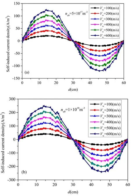
Figure 9.Self-induced current density at different TMF velocities;ve=1 GHz, V0=1000 m s−1, Vw=100-600 m s−1, B=0.15 T.(a) ne0=5×10¹⁷ m−3, (b) ne0=1×10¹⁸ m−3.
ne0=5×10¹⁷m−3and 1.40×10¹⁸m−3(peak electron density near the antenna window at an altitude of 40 km)[14],collision frequency ve=1 GHz,the plasma layer thickness is set to 0.05 m, and the applied magnetic fields for the L-band(1.575 GHz), S-band (2.3 GHz), C-band (5.7 GHz) and X-band (9.21 GHz) are 0.02 T, 0.03 T, 0.06 T and 0.1 T,respectively.The conventional L-, S-, C- and X-bands have experienced radio blackouts with an attenuation criterion of−30 dB [30, 31].The effects of the TMF on these conventional bands (figure 7) represent the change in attenuation with the TMF velocity by using induced current and in the TMF method by using injected current (J=200 A m−2).In the simulation results, the attenuation decreases with increasing TMF velocity.A comparison of the velocity when the EM wave penetrates the plasma for the two methods is presented in table 1.Taking into account the typical communication frequency band being used in reentry,the L-band(1.575 GHz) is considered.From the proposed model, the velocity required to mitigate blackout is approximately 7680 m s−1, with the plasma electron density rising to 1.4×10¹⁸m−3.Under the same set of plasma parameter settings, if the communication frequency is increased, the velocity required to break through the blackout gradually decreases.The corresponding electron densities for blackouts in the L-, S-, C- and X-bands are 2.25×10¹⁷m−3,2.6×1017m−3, 5.7×10¹⁷m−3and 1.2×10¹⁸m−3for identical parameter settings used with the analytical solution of the attenuation of EM waves propagating through plasma.We find (see table 1) that when the TMF velocity is approximately 3030 m s−1, the tolerance of the electronic density in blackouts increases by 2, 1.9, 1.75 and 3 times for the L-, S-, C- and X-bands, respectively, at the altitude of 40 km.Only by increasing the TMF velocity from 40 m s−1to 3100 m s−1does the mitigation effect reach the same level
(forne0=5×10¹⁷m−3) as in previous work (table 1).Although our proposed method requires a much higher TMF velocity than for the other method when the waves propagate through the plasma, injecting current into the plasma is unnecessary.Therefore, the self-induced current is increased by simply increasing the TMF velocity, thereby improving the EM wave transmission and halting blackouts.With proven high-frequency magnetic-core technology, generating a TMF with such a high velocity is easier than injecting current into the plasma.Therefore, the TMF method based on the induced current is feasible and practicable in sidestepping problems caused by electrode exposure and reducing the need to apply magnetic fields.
5.Model verifications
In this paper, when the TMF velocity Vw=0 ms−1, the reduction ratioN(x) in equation (20) can be found asN(x)=1,which means there is no reduction effect on electric density.The phase sequence of the magnetic pole is shown in figure 1(a).Various plasma parameters are established using numerical simulation software to verify the proposed method.The current density induced by the TMF is obtained simultaneously with the parameters being set as:initial electric densityne0=5×10¹⁷m−3andne0=1×10¹⁸m−3, ve=1 GHz, V0=1000 m s−1, and the TMF velocity ranging from 100 m s−1to 600 m s−1.Figure 8 shows the simulation results of the distributions of induced current density with the TMF (Vw=600 m s−1) at different moments.It is found that the current density can be induced by the TMF in plasma.
Figure 9 shows the current density induced by the TMF at different velocities.It follows from the figure that the induced current density gradually increases with increasing TMF velocity, which is in good agreement with the theory presented in this paper.Comparison of results of the analytical simulation and the numerical simulation of the induced current density obtained with various plasma parameters is presented in table 2.The table shows that the analytical solutions are similar to the numerical simulation results at ve=1 GHz.
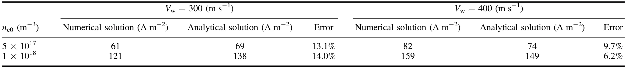
Table 2.Comparison of the numerical and analytical solutions for induced current density.

Figure 10.Attenuation during the reentry phase of an RAM-C module without applying the TMF.
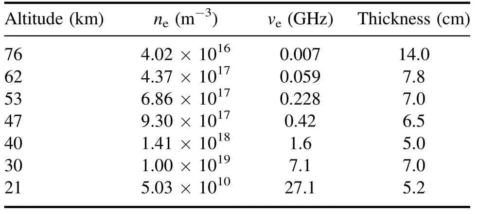
Table 3.Typical plasma sheath parameters for RAM-C [32].
Figure 10 shows the relation between attenuations and reentry altitude.The plasma parameters at different reentry altitudes used in the proposed model are given in table 3[32],and a comparison of results of the proposed model and the RAM-C measurement data is presented in table 4.It can be found that the attenuation results without applying the TMF are consistent with the measurement data.
6.Discussion
In a previous work [20], we obtained an electron density ofne0=1×10¹⁸m−3that can be reduced by up to an order of magnitude whenB0=0.15 T, Vw=80 m s−1, and ve=1 GHz.Indeed, a viable self-induced current exists in all instances.If generated by a TMF velocity Vw=80 m s−1, it produces a value of approximately 8 A m−2.Assuming the velocity is low, the self-induced current generated is much lower than the external injection current of 200 A m−2.In this case, the self-induced current can be ignored.With the objective of increasing the coupling current by injecting current into the plasma, the previous work showed that blackouts can be mitigated.Nevertheless,overcoming a series of associated problems, such as electrode shielding and electrode erosion, was needed.Our study was tasked with realizing blackout mitigation by increasing the TMF velocity,thereby increasing the self-induced current in the plasma,and achieving a similar order-of-magnitude reduction to using an injected current.
The proposed TMF method in this paper has shown that the current density can be induced in the plasma to reduce electron number density near the reentry vehicle.Although the induced current can generate Joule heating in plasma, the increase in aerodynamic heating with Joule heating by the induced current can be neglected.Taking typical values in the literature as an example, for the TMF velocity Vw= 1000 m s−1, the induced current density J≈200 A m−2,ne0= 1×10¹⁸m−3, and ve=1 GHz.In a plasma adjacent to the antenna window with a volume of 10 cm×10 cm×3 cm, the power generated is approximately 15 W and the Joule heating is approximately 1.5×10⁻³J in the duration of flow field passing through the antenna window, so the Joule heating generated by the induced current can be neglected.
Although the analytical solution is useful in describing the effect of self-induced currents on electron density reduction, the instability of the plasma fluid was not considered.Instead,to simplify the model,the plasma fluid at the antenna window was considered to be approximately uniform and constant.The applied magnetic field only has a component in the z-direction in this one-dimensional TMF model.However,the magnetic field generated by the TMF generator is threedimensional, and hence a three-dimensional model for electron density reduction should be considered.
7.Conclusion
An analytical model based on self-induced current was proposed to further improve the plasma fluid model of the TMF.Compared with a reported model, the TMF method based on self-induced current can reduce electron densities by up to an order of magnitude, and can also eliminate L-, S-, C- and X-band blackouts at an altitude of 40 km.The verification of this theory showed that this TMF method has the potential tomitigate blackouts, allowing continuous communications during a period when radio blackout inevitably occurs.

Table 4.Comparison of the proposed model and the experiment.
Not only can the TMF drive the plasma in non-contact ways but the direction of the TMF velocity can also be controlled, and therefore, a non-contact directional manipulation of the plasma can be performed when applying the TMF method.Experimental studies concerning the influence of the TMF on the plasma fluid will be conducted.
Acknowledgments
This work was supported by National Natural Science Foundation of China (Nos.61771370, 61701381, and 11704296).
ORCID iDs
Shaoshuai GUO (郭韶帅) https://orcid.org/0000-0003-3657-261X
杂志排行
Plasma Science and Technology的其它文章
- The structure of an electronegative magnetized plasma sheath with non-extensive electron distribution
- The effect of forced oscillations on the kinetics of wave drift in an inhomogeneous plasma
- Numerical simulation of impact of supersonic molecular beam injection on edge localized modes
- Effect of background fluctuation on velocity diagnostics by Mach probe
- New method for rekindling the explosive waves in Maxwellian space plasmas
- Molecular dynamics simulations of the interaction between OH radicals in plasma with poly-β-1-6-N-acetylglucosamine