Harvesting Microalgae Biomass Using Sulfonated Polyethersulfone (SPES)/PES Porous Membranes in Forward Osmosis Processes
2020-11-30ZHOUQiYANGYangWANGXiaojuanWANGQunWANGShuxinGAOXueliandGAOCongjie
ZHOU Qi, YANG Yang, WANG Xiaojuan, *, WANG Qun, WANG Shuxin, GAO Xueli, *, and GAO Congjie
Harvesting Microalgae Biomass Using Sulfonated Polyethersulfone (SPES)/PES Porous Membranes in Forward Osmosis Processes
ZHOU Qi1), 2), YANG Yang1), 2), WANG Xiaojuan1), 2), *, WANG Qun3), WANG Shuxin4), GAO Xueli1), 2), *, and GAO Congjie1), 2)
1)Key Laboratory of Marine Chemistry Theory and Technology, Ministry of Education, Ocean University of China,Qingdao 266100, China 2) College of Chemistry and Chemical Engineering, Ocean University of China, Qingdao 266100, China 3)College of Chemical and Environmental Engineering, Shandong University of Science and Technology, Qingdao 266590, China 4) Zhaoyuan Marine and Fishery Supervision and Inspection Squadron, Zhaoyuan 265400, China
This study was performed to investigate the availability of forward osmosis (FO) for microalgae harvesting using sulfonated polyethersulfone (SPES)/PES porous membranes. In FO process, porous membranes (<25.0Lm−2h−1) exhibited more superior water flux than TFC FO membranes (<2.6Lm−2h−1). Furthermore, the incorporation of SPEShas been demonstrated to enhance membrane performance. The effects of SPES content on pore structure and separation performance were investigated. Compared with pure PES porous membranes, porous membranes with 40% SPES yielded an improved hydrophilicity and greater porosity. It exhibited two times higher water fluxes than the pure PES porous membrane. For microalgae harvesting, AL-FS mode (active layer facing the feed solution) was more favourable than AL-DS mode (active layer facing the draw solution) because less deposited microalgae on the active layer mitigate the membrane biofouling. FO operation combined with SPES/PES porous membranes is conducive to preserving microalgae cell integrity under the mild condition. In addition, FO membrane can be cleaned by a simple water rinse. Potential implications were highlighted as a sustainable method for microalgae harvesting because of no pressure input and less chemical cleaning demand.
forward osmosis; porous membrane; sulfonated polyethersulfone; microalgae harvesting; cell integrity
1 Introduction
Microalgae has been recognized as a promising raw material for producing biodiesel because of its high photosynthetic efficiency, short growth cycle, high oil content and high value by-products (.., polysaccharides, protein) (Laamanen., 2016). Microalgae cultivation and harvesting has also been spotlighted as one of the mitigation processes for global warming by carbon dioxide capture (Pienkos and Darzins, 2009). Nevertheless, many issues surrounding the scale and sustainability of microalgae harvesting have yet to be resolved because of low concentration (0.5–1.0gL−1) and small size of microalgae cells (3–30μm in diameter).
Most existing microalgae harvesting processes are prohibitively energy intensive, such as coagulation, flotation,centrifugation, gravity sedimentation, microfiltration and ultrafiltration.Gudin and Thepenier estimated that biomass harvesting can contribute 20%–30% to the total biodiesel production cost (Gudin and Thepenier, 1986). Hence, technologies which use fewer external inputs need to be developed to make microalgae harvesting processes sustainable before production of microalgae-derived biodiesel become a large-scale commercial reality. Forward osmosis (FO), an emerging sustainable separation process, can proceed without external hydraulic pressure. It theoretically utilizes natural driving force, generated by salinity-gradient solutions across a semi-permeable membrane, to make water molecular transport from the more dilute feed solution (FS) to the concentrated draw solution (DS).Owing to no hydraulic pressure, FO can mitigate the tendency for microalgae cells breakage which may cause the loss of target products from the cell interior. The small particles generated by cells breakage may also aggravate the membrane fouling by blocking the surface pores and then forming a cake layer on the membrane surface (Zhang., 2010). Due to the absence of hydraulic pressure and temperature variation that may be adverse to the microalgae, FO is of great potential to be an alternative dewatering method for large-scale microalgae harvesting. Nevertheless, dewatering rate of current available FO membranes (.., TFC and CTA membranes) is still low (range 1.8–2.4Lm−2h−1) due to the intrinsic property of traditional FO membranes (Buckwalter., 2013; Wang., 2019), which hampers its applicability in actual industrial production.
To achieve superior dewatering rate for FO, other types of membranes (.., UF-like and NF-like membranes) should be designed and optimized for harvesting microalgae. Qi. (2016) has suggested that porous membranes (UF-like membranes) exhibited excellent permeability-selectivity performance in oil/water separation under the condition of relatively large draw solutes, thereby avoiding the permeability-selectivity counterbalance for traditional FO membranes. The large draw solute molecule produces a trans-membrane osmotic pressure that draws water through the membrane, while the porous membrane acts as a barrier to oil droplets, microalgae cells or other particles. Recently, related work has shown that hydrophilic membranes prepared by incorporating a certain amount of sulphonated polymers into the membrane matrix are more capable of obtaining high water flux, such assulfonated polyethersulfone (SPES)/PES (Blanco., 2001; Rahimpour., 2010), polysulfone (PSf)/sulfonated poly(ether ketone) (SPEK) (Han., 2012), PSf/sulfonated polyphenylenesulfone (sPPSU) (Widjojo., 2013). These sulfonated polymers were proved to further enhance UF performance by optimizing microstructure and hydrophilicity of membranes (Blanco., 2002; Blanco., 2006). Based on the aforementioned fundamental understandings, SPES/PES porous membranes can be a good option for harvesting microalgae in FO.
In this study, the incorporation of SPES in the PES membrane was applied to harvest microalgae with enhanced FO dewatering rate. We investigated the water flux behavior of porous SPES/PES membranes and the effects of membrane orientation on microalgae dewatering rate so as to provide insightful guidelines for the application of FO process in large-scale microalgae harvesting. The mild condition and respectable dewatering rate of FO process endow SPES/PES porous membranes with applicability in microalgae harvesting.
2 Materials and Methods
2.1 Feed and Draw Solutions
In FO tests, ultrapure water was used as feed solution. It was provided by a Millipore water purification system (Milli-Q, Academic, Millipore Corporation, Billerica, MA) with a resistivity of 18.2MΩ.cm. Poly(sodium-p- styrenesulfonate) (PSS) (Mw=80kDa) was used as draw solute. The concentration of PSS ranged from 0.25wt% to 0.75wt%.
2.2 Microalgae Suspensions
The green microalgae,, was chosen as the experimental organism because of its ubiquitousness in water environment and its utilization for production of protein (50%–65% of dry weight) and lipid content (14%–56% of dry weight) (Gouveia., 2009).was purchased from the Institute of Oceanology, Chinese Academy of Sciences (IOCAS). The microalgae was cultured in BG-11 culture medium prepared from pure chemicals dissolved in deionized (DI) water (Andersen, 2005). The fresh cultures were taken at the end of exponential growth phase. Before tests, the cell concentration reached 0.62gL−1(dry weight). Microalgae dry weight was determined gravimetrically by filtration using Whatman glass fiber filters and dried until constant weight at 105℃.
2.3 SPES Synthesis and Characterization
SPES was synthesized by using sulforic acid (98%) as the sulfonating agent. PES powder was dissolved in sulfuric acid in a glass reactor equipped with a mechanical stirred. The temperature for polymer dissolution was 25℃. The reported reaction time was the total time for polymer dissolution and reaction. After a determined reaction time, the reaction mixture was poured into a large amount of frozen ice water under rapid stirring to precipitate in the acidic form of SPES. The resulting precipitate was filtered and washed with DI water repeatedly and then the SPES was dried under vacuum at 40℃.
The ion exchange capacity (IEC) is defined as the ratio of exchanged H+(in mLequiv.g) to the weight of the dried polymer. IEC was determined by suspending 0.3g of SPES in 30mL of 2molL−1NaCl solution for 24h to liberate the H+ions. Then, the titration was done with standardized 0.1molL−1NaOH solution using phenolphthalein as an indicator. The IEC was calculated according to Eq. (1) (Rahimpour, 2010):

NaOH,NaCl, anddryare volume of NaOH, volume of NaCl and weight of dry PES, respectively. Degree of sulfonation (DS) is the average number of sulfonic acid groups (-SO3H) in per repeating unit of SPES polymer chain.can be calculated from the IEC.Thus, thecan be obtained from Eq. (2) (Rahimpour., 2010):

2.4 Membranes Preparation and Characterization
Thin-film composite (TFC) membranes: newly commercial flat-sheet FO membranes dissembled from a 4040 membrane element (Toray Chemical Korea Company Limited, Jung-gu, Seoul, South Korea) were used in our experiment. TFC membrane has an asymmetric structure, which consists of three layers: the dense polyamide active layer, the porous support layer and the ultrathin support backing.
Porous membranes: porous membranes were prepared by the phase inversion method. PES-SPES (lab-made with sulfonation degree of 15%) solution was dissolved in a mixed solvent system in which LiCl had been dissolved in N, N-dimethylacetamide (DMAc). The composition of the casting solutions was summarized in Table 1. Casting dope was prepared under constant mechanical stirring at 70℃ for 12h, which was heated in a water bath. The dope solution could be used for casting after 24h of standing at room temperature (25℃). A casting knife, which had been set a gate height of 120μm, was used to spread the casting solution onto a clean glass plate. After 30s exposure to air, the glass plate was then immersed in a coagulation bath (DI water at 25℃). The formed membrane was washed with DI water and stored in DI water until test.
The surface structure of the membranes was characterized with S-4800 scanning electron microscope (Hitachi, Japan) at a 15kV accelerating voltage. For the SEM observation, all the membrane samples were coated with gold by a sputter coating machine. Contact angle measurements were performed with a DSA100 contact angle analyzer (Kruss, Germany). The membrane porosity was measured using dry-wet weight method (Zheng., 2006; Wang., 2018). To measure the porosity of porous membrane, membrane sample was soaked in water bath for 24h and weighed (1, g) after carefully and quickly removing the excess water on the surface by absorbing paper. The wet sample was then dried in a vacuum oven at 40℃for 24h and re-weighed (2, g). Porosity was calculated from Eq. (3) below where1,2,ρ, ρare the weights of wet and dry membranes, the density of DI water (ρ, 1.0gcm−3) and PES (ρ, 1.37gcm−3) respectively.

The Fourier-transform infrared spectroscopy (FTIR, Bruker Tensor 27) was performed at the room temperature. Pure water permeability (A) of the membrane was measured according to Wang. (2017). Conductivity of FS (1wt% PSS) and permeate water were measured by a conductivity meter (INESA, China), by which PSS rejection could be calculated.
Water flux (J) in FO and rejection () were calculated from Eqs. (4) and (5) below whereΔm,ρ,cell,C,C,are the mass change of the DS (g), the density of the DS (gL−1), the membrane area (m2), concentration in the permeate and feed solution (1wt% PSS), the measurement time (h), respectively.


Table 1 Composition of the casting solutions
2.5 FO Experimental Setup and Operating Procedures
The laboratory-scale FO evaluation system was depicted in Fig.1. The channel of the cross flow membrane cell made of stainless steel has a dimension of 93mm, 30 mm, 1mm length, width and depth, respectively. Variable speed gear pump (WT-3000 1JA, Longerpump, China) was used to recirculate the DS and FS in the same cross-flow velocity of 0.27ms−1. A digital scale balance (PL4002, Mettler Toledo, Swiss) interfaced with a computer was used to calculate the water flux (J) of FO process by monitoring the weight changes of the DS.

Fig.1 Schematic diagram of an evaluation system for porous membranes in FO processes.
3 Results and Discussion
3.1 FO Performance of SPES/PES Membranes
Fig.2 compared the water fluxes of porous membranes and TFC membranes. In FO process, porous membranes (< 25.0Lm−2h−1) exhibited more superior water flux than TFC FO membranes (< 2.6Lm−2h−1). It is because that water permeability (A) of porous membranes (as illustrated in Table 2) is much higher than that of TFC membranes (A=6.90Lm−2h−1bar−1). Pure water permeability of commercial TFC membranes can be obtained in our prior studies (Wang., 2017; Yang., 2018). Porous membranes perform similar asymmetric morphology (active layer and porous layer, illustrated in Fig.4) with traditional FO membranes (.., TFC membranes). Nevertheless, the pore distribution of porous membranes is commonly larger than the dimension of salt ions, resulting in the failure of salt retention. Although porous membrane did not show any rejection of salt, its rejection of PSS was more than 96.8%, suggesting that PSS can be used as draw solution for porous membranes in FO process.
The porous membrane was more permeable compared to TFC membrane in FO process due to its lack of dense rejection layer. For TFC membrane, water fluxes (<2.6 Lm−2h−1) were very low due to their low pure water permeability (A=6.90Lm−2h−1bar−1) and low driving force (low draw solution concentration). To further improve porous membrane performance for FO, sulfonated polyethersulfone (SPES) was introduced in the porous membrane. FTIR allowed us to verify the successful incorporation of SPES in the membrane. In Fig.3, for the SPES/ PES (40:60) membrane, a characteristics peak at 1026 cm-1is observed due to the stretching vibration of the S=O bond in sulfonic acid groups. SPES content has a significant influence on the porous layer surface morphology, whilst it rarely affects the active layer (Fig.4). Increasing SPES content can result in larger pores in porous layer, which reduce the water transfer resistance. In addition, the incorporation of SPES can enhance the porosity and hydrophilicity, as illustrated in Table 2. Contact angle measurements showed a gradual reduction in water contact angle from 64.7˚ to 49.3˚ with increasing SPES content.
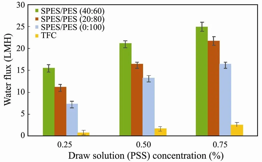
Fig.2 FO water flux of membranes with varying SPES/ PES composition using DI water as feed solution.

Fig.3 FTIR spectra of pure PES membrane and SPES/PES (40:60) membrane. A characteristics peak at 1026cm−1 is observed due to the stretching vibration of the S=O bond in sulfonic acid groups, indicating the successful incorporation of SPES in the membrane.

Fig.4 The SEM observation of (A) pure PES membrane; (B) SPES/PES (20:80) membrane and (C) SPES/PES (40:60) membrane. Porous membranes perform similar asymmetric morphology (active layer and porous layer) with traditional FO membranes. A and P present active and porous layer, respectively.
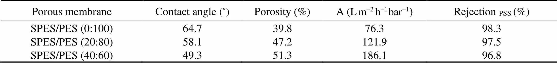
Table 2 Contact angle, porosity, molecular-weight cut-off and pure water permeability of porous membranes
Filtration experiment in AL-FS orientation was performed with 0.25–0.75 wt% PSS draw solution to evaluate the FO performance of SPES/PES membranes (Fig.2). It can be clearly seen that increased PSS concentration, functioning as driving force in FO, could augment the water flux. Furthermore, the water flux was enhanced noticeably with an increase in SPES content from 0% to 40%. The porous membrane with 40% SPES exhibited two times higher water fluxes compared with the pure PES porous membrane at 0.25wt% PSS solution concentration. The augment in water flux can be attributed to more porous structure, greater porosity and increased membrane hydrophilicity resulting from SPES incorporation. SPES/PES porous membranes with asymmetric structure exhibited respectable water flux, endowing FO with promising potential for application in harvesting microalgae biomass.
3.2 SPES/PES Membranes for Microalgae Harvesting in FO
3.2.1 AL-FS mode
Fig.5 showed the FO water flux of the SPES/PES membranes in AL-FS mode during 3h microalgae/water separation. Baseline tests were performed using pure water as FS. Dewatering experiments were conducted to determine if microalgae affected the FO dewatering rateswhen FS was microalgae suspension. Fouling can also be evaluated by comparing dewatering rates to the corresponding baseline values. Under otherwise identical operation conditions, for pure PES membrane and SPES/ PES (20:80) membrane, the dewatering rates of microalgae/water separation were comparable to the baseline values, suggesting that minimal membrane fouling had occurred. Nevertheless, for SPES/PES (40:60) membrane, a difference could be observed between dewatering rates of microalgae/water separation and baseline values.Higher fluxes cause relatively higher flux decline during the test period of 3h, which might be explained by the greater permeation drag force at increased flux. The effect of water flux on membrane biofouling can be attributed to the permeation drag rooting in convective flow toward the membrane, as illustrated in Fig.6.

Fig.5 FO water flux of the SPES/PES membranes in AL-FS mode during 3h microalgae/water separation. (a) SPES/PES (0:100); (b) SPES/PES (20:80) and (c) SPES/PES (40:60).

Fig.6 Schematic illustration of the influence of water flux on membrane biofouling. At a higher water flux (J0), deposition/adhesion of microalgae (biofouling) is promoted by greater hydrodynamic force, dragging the microorganisms toward the porous membrane surface.
3.2.2 AL-DS mode
The results of FO dewatering experiment in AL-DS mode are shown in Fig.7. The water fluxes in AL-DS mode were higher than that in AL-FS mode at all DS concentration when pure water was used as the FS (Baseline test). It is attributed to less significant internal concentration polarization (ICP) in AL-DS mode when pure water as FS is at the porous layer side (Gray., 2006). Fig.7 also indicated the influence of microalgae on the FO dewatering rates in AL-DS mode. During the initial stage of microalgae filtration, the water fluxes were nearly equivalent to that of baseline test. Nevertheless, after the first one-hour filtration, declines in water flux were observed in microalgae filtration. And water flux declined more significantly in AL-DS with an increase in the SPES content, owing to the asymmetric morphology of porous membranes. Since porous layer exhibited more porous structure than active layer (Fig.3), microalgae cells were more inclined to be entrapped in the porous layer (AL-DS mode) than in the active layer (AL-FS mode). The entrapped microalgae cells may aggravate the porous membrane biofouling by blocking the surface pores. Such results implied thatSPES/PES porous membranes in AL-FS mode were potentially more suitable than in AL-DS mode for harvesting microalgae due to its low fouling potential and stable dewatering rate.
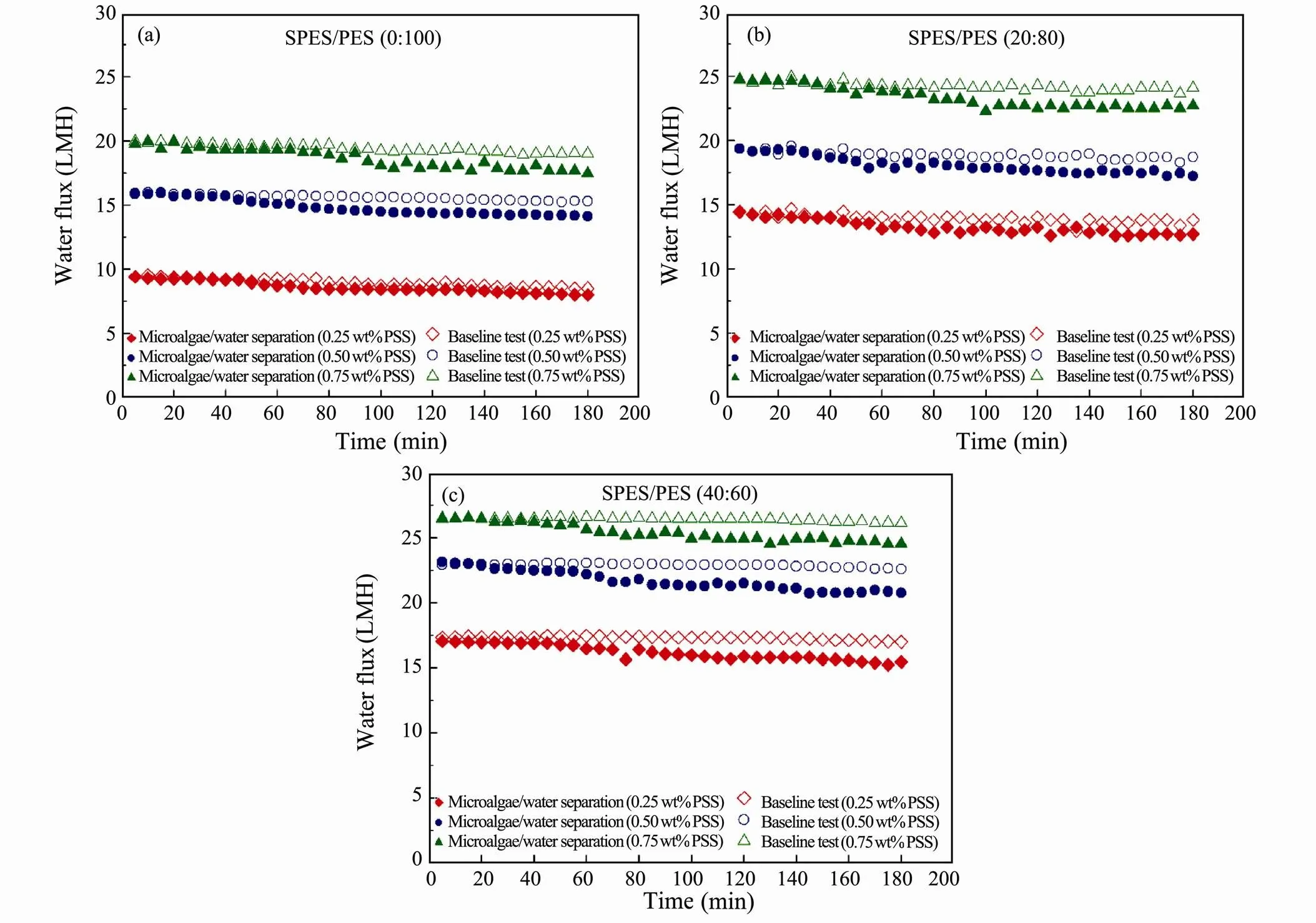
Fig.7 FO water flux of the SPES/PES membranes in AL-DS mode during 3h microalgae/water separation. (a) SPES/PES (0:100); (b) SPES/PES (20:80) and (c) SPES/PES (40:60).
3.3 Microalgae Cell Integrity and Membrane Cleaning
The extraction of high added-value compounds from microalgae suspensions should avoid deterioration and loss of functionality (Galanakis, 2012). Since cell breakage could cause the loss of target products from the cell interior, cell integrity is an important factor during microalgae harvesting. FO can proceed under relatively mild conditions (no hydraulic pressure input) with desirable water flux and better cell integrity in microalgae dewatering.Section 3.2 had demonstrated that AL-FS mode exhibited more stable and superior dewatering rate compared with AL-DS mode, indicating that AL-FS mode is more favourable in dewatering microalgae. The images of fouled membranes after 3h microalgae/water separation are shown in Fig.8.

Fig.8 The SEM images of (A) pure PES membrane; (B) SPES/PES (20:80) membrane and (C) SPES/PES (40:60) membrane. N, F and C present new, fouled and cleaned membrane, respectively.
Experiments were conducted with microalgae suspension on the active layer (AL-FS mode) in FO. Intactcells were deposited on the membrane surface because of no hydraulic pressure input. Besides, few signs of microalgae cells compaction can be observed in Fig.8. This is in stark contrast with observation under micro- and ultra-filtration, where hydraulic pressure (1–3 bar) is generally applied (Babel and Takizawa, 2010; Sun., 2013).The SEM images of membranes after cleaning with DI water are shown in Fig.8. Owing to no signs of microalgae cells compaction, microalgae cells deposited on the active layer can be easily removed, as shown in Fig.8. Similar phenomenon was also found by Mi and Elimelech (2010)for cleaning a fouled FO membrane used in treating alginate solution. FO membrane can be cleaned by a simple water rinse, indicating that operating in FO process may offer an advantage of reducing or even eliminating the demand for chemical cleaning, and thereby reducing overall operation cost.
4 Conclusions
In this study, we prepared a hydrophilic SPES/PES porous membrane for harvesting microalgae in FO process. Dewatering experiments suggested that SPES/PES porous membrane could achieve superior FO water fluxes by optimizing microstructure and hydrophilicity of porous membranes.AL-FS mode was more favourable than AL- DS mode in microalgae harvesting since microalgae were inclined to be entrapped in the porous layer, which may aggravate the porous membrane biofouling. Few signs of microalgae cells fragments can be observed because the mild condition (no hydraulic pressure input), which is conducive to preserving microalgae cell integrity.High water permeation, better microalgae cell integrity and less chemical cleaning demand give a promising prospect for FO combined with SPES/PES membranes as an initial dewatering step in large-scale microalgae harvesting.
Acknowledgements
This work was supported by the National Natural Science Foundation of China (No. 21576250), the Key Research Project of Shandong Province (No. 2018CXGC 1003), and the Young Taishan Scholars Program of Shandong Province.
Andersen, R. A., 2005.. Elsevier, Netherlands, 1-22.
Babel, S., and Takizawa, S., 2010. Microfiltration membrane fouling and cake behavior during algal filtration., 261 (1-2): 46-51.
Blanco, J. F., Nguyen, Q. T., and Schaetzel, P., 2001. Novel hydrophilic membrane materials: Sulfonated polyethersulfone Cardo., 186 (2): 267-279.
Blanco, J. F., Nguyen, Q. T., and Schaetzel, P., 2002. Sulfonation of polysulfones: Suitability of the sulfonated materials for asymmetric membrane preparation., 84 (13): 2461-2473.
Blanco, J. F., Sublet, J., Nguyen, Q. T., and Schaetzel, P., 2006. Formation and morphology studies of different polysulfones-based membranes made by wet phase inversion process., 283 (1-2): 27-37.
Buckwalter, P., Embaye, T., Gormly, S., and Trent, J. D., 2013. Dewatering microalgae by forward osmosis., 312: 19-22.
Galanakis, C. M., 2012. Recovery of high added-value components from food wastes: Conventional, emerging technologies and commercialized applications., 26 (2): 68-87.
Gouveia, L., and Oliveira, A. C., 2009. Microalgae as a raw material for biofuels production., 36 (2): 269-274.
Gray, G. T., McCutcheon, J. R., and Elimelech, M., 2006. Internal concentration polarization in forward osmosis: Role of membrane orientation., 197 (1-3): 1-8.
Gudin, C., and Thepenier, C., 1986. Bioconversion of solar energy into organic chemicals by microalgae.,6: 73-110.
Han, G., Chung, T. S., Toriida, M., and Tamai, S., 2012. Thin-film composite forward osmosis membranes with novel hydrophilic supports for desalination., 423: 543-555.
Laamanen, C. A., Senhorinho, G. N., Ross, G. M., and Scott, J. A., 2016. Heat-aided flocculation for flotation harvesting of microalgae., 20: 213-217.
Mi, B., and Elimelech, M., 2010. Organic fouling of forward osmosis membranes: Fouling reversibility and cleaning without chemical reagents., 348 (1-2): 337-345.
Pienkos, P. T., and Darzins, A. L., 2009. The promise and challenges of microalgal-derived biofuels., 3 (4): 431-440.
Qi, S., Li, Y., Wang, R., and Tang, C. Y., 2016. Towards improved separation performance using porous FO membranes: The critical roles of membrane separation properties and draw solution., 498: 67-74.
Rahimpour, A., Madaeni, S. S., Ghorbani, S., Shockravi, A., and Mansourpanah, Y., 2010. The influence of sulfonated polyethersulfone (SPES) on surface nano-morphology and performance of polyethersulfone (PES) membrane., 256 (6): 1825-1831.
Sun, X., Wang, C., Tong, Y., Wang, W., and Wei, J., 2013. A comparative study of microfiltration and ultrafiltration for algae harvesting., 2 (4): 437-444.
Wang, Q., Gao, X., Ma, Z., Wang, J., Wang, X., Yang, Y., and Gao, C., 2018. Combined water flux enhancement of PES- based TFC membranes in ultrasonic-assisted forward osmosis processes., 64: 266-275.
Wang, Q., Gao, X., Zhang, Y., Wang, J., Xu, Y., Ji, Z., Wang, X., and Gao, C., 2017. Alleviation of water flux decline in osmotic dilution by concentration-dependent hydraulic pressurization., 117: 593-603.
Wang, Q., Ma, Z., Wang, J., Sun, Z., Sun, Y., Jiang, Y., and Gao, X., 2019. Cost-oriented optimization of osmotic dilution based on concentration-dependent hydraulic pressure., 467: 113-124.
Widjojo, N., Chung, T. S., Weber, M., Maletzko, C., and Warzelhan, V., 2013. A sulfonated polyphenylenesulfone (sPPSU) as the supporting substrate in thin film composite (TFC) membranes with enhanced performance for forward osmosis (FO)., 220: 15-23.
Yang, Y., Gao, X., Li, Z., Wang, Q., Dong, S., Wang, X., Ma, Z., Wang, L., Wang, X., and Gao, C., 2018. Porous membranes in pressure-assisted forward osmosis: Flux behavior and potential applications., 60: 160-168.
Zhang, X., Hu, Q., Sommerfeld, M., Puruhito, E., and Chen, Y., 2010. Harvesting algal biomass for biofuels using ultrafiltration membranes., 101 (14): 5297- 5304.
Zheng, Q. Z., Wang, P., Yang, Y. N., and Cui, D. J., 2006. The relationship between porosity and kinetics parameter of membrane formation in PSF ultrafiltration membrane., 286 (1-2): 7-11.
. E-mail: safiya0524@163.com
E-mail: gxl_ouc@126.com
November 11, 2019;
June 26, 2020;
September 24, 2020
(Edited by Ji Dechun)
杂志排行
Journal of Ocean University of China的其它文章
- Numerical Simulation and Risk Analysis of Coastal Inundation in Land Reclamation Areas: A Case Study of the Pearl River Estuary
- Variation of Yellow River Runoff and Its Influence on Salinity in Laizhou Bay
- Cold Water in the Lee of the Batanes Islands in the Luzon Strait
- Preliminary Design of a Submerged Support Structure for Floating Wind Turbines
- Inversion of Oceanic Parameters Represented by CTD Utilizing Seismic Multi-Attributes Based on Convolutional Neural Network
- Trace-Norm Regularized Multi-Task Learning for Sea State Bias Estimation