A commutation analytical model for quench protection of the CFETR central solenoid model coil
2020-06-28TianbaiDENG邓天白GeGAO高格YananWU吴亚楠
Tianbai DENG (邓天白), Ge GAO (高格), Yanan WU (吴亚楠),
Jun LI (李俊)1, Peng FU (傅鹏)1,2, Sheng LIU (刘生)3 and Min WANG (王敏)3
1 Institute of Plasma Physics, Chinese Academy of Sciences, Hefei 230031, People’s Republic of China
2 University of Science and Technology of China, Hefei 230026, People’s Republic of China
3 China International Nuclear Fusion Energy Program Execution Center, Beijing 100862, People’s Republic of China
Abstract A central solenoid model coil will be set up to develop and verify the technique for the full-size central solenoid coil of the China Fusion Engineering Test Reactor. In case of quench and failures of superconducting coils,the quench protection(QP)system,which employs fuse-based commutation technology,is designed.This paper presents an analytical model to investigate the commutation process in the QP circuit. The model consists of the QP circuit equations, the breaker arc model,the fuse pre-arc model,and the fuse arc model.The model is employed in the whole commutation process including current transfer from breaker branch to the fuse branch model,then from fuse branch to the discharge resistor branch,and current decrease to zero in the discharge resistor. The experiment result verified the effectiveness of the presented model. The model might be helpful for design of the fuse and optimization of the commutation circuit.
Keywords:quench protection,fuse model,arc model,superconducting magnet,central solenoid model coil(Some figures may appear in colour only in the online journal)
1. Introduction
The China Fusion Engineering Test Reactor(CFETR)will be a new tokamak device to be conducted in China[1].The design of the superconducting magnet project has been carried out to bridge the technical gap between ITER and DEMO [2, 3]. The CFETR magnet system consists mainly of a central solenoid(CS)coil with 8 modules,16 toroidal field(TF)coils,6 poloidal field (PF) coils, and 18 correction coils (CC) [4]. In order to develop the technique for the full-size CS coil,the development of the central solenoid model coil(CSMC)is set up first[5].The maximum operation current of CSMC is designed to be 51.25 kA. In case of quench and failures of superconducting coils,the energy stored in the coils should be rapidly removed by the quench protection (QP) system for the safe operation of the coil.In recent years,several technologies for direct current(DC)current interrupters have been adopted in other fusion experiments. In JT60-SA, bypass switch and a set of paralleled integrated gate commutated thyristors are used as solid-state switch to cut off the coil current directly [6]. In ITER, the mechanical switch and thyristor in parallel with the counter-pulse network are employed in the quench protection system called fast discharge unit (FDU) [7]. For CFETR, investigations about the quench protection unit are still in the process[8–12].With the demand of the high reliability and simple for construction, the mature solution of fuse-based commutation,which has been employed in EAST and LHD, is more applicable [13, 14]. The designed schematic diagram of the QP system in series with the power supply and the switch network unit is shown in figure 1[15,16].
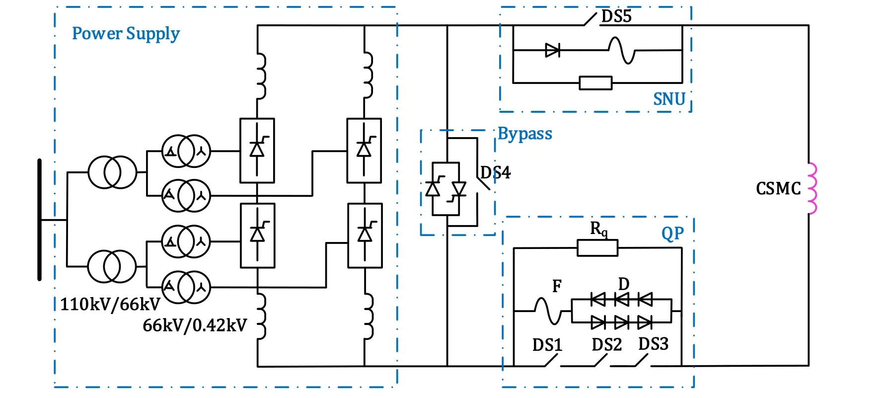
Figure 1. Schematic diagram of the QP system in series with the power supply and the switch network unit.
The QP circuit consists of the DC circuit breakers (DS1-DS3), diodes (D), fuse (F) and discharge resistor (Rq). Three DC circuit breakers (DCCBs) are connected in series to improve the reliability of the protection system. The diodes connected with the fuse in series provide voltage threshold to prevent the current from flowing through the fuse branch during normal operation of the coil. When the coil has a quench, the DS breakers would rapidly be opened after receiving the detection signals.Then the current is transferred to the discharge resistor with the help of fuse melting.
As the key component in the QP circuit, the fuse can reduce the breaker’s arc energy and produce a high pulse voltage for making current flow into the discharge resistor.By employing the finite element method, some numerical investigations have been done about the DCCB and fuse respectively [17, 18]. However, the numerical simulation of fusebased commutation has seldom been seen in the literature. To investigate the commutation process in the QP circuit, an analytical model is presented in this paper.Section 2 introduces the three stages of the whole commutation process and gives the model descriptions. The model includes the QP circuit equations,the breaker arc model,and the detail fuse model.All calculations were coded in Matlab.In section 3,an engineering experiment is carried out and the effectiveness of the presented model is verified.The model might be helpful for design of the fuse and optimization of the commutation circuit.
2. Simulation model
Figure 2(a) shows an equivalent circuit of the CSMC QP circuit. The QP circuit consists of three branches: the breaker branch, the fuse branch, and the resistor branch. Each branch has a resistor and an inductance to represent the resistance and the stray inductance of the branch respectively.The three rapid circuit breakers and the fuse are simplified as the voltage sourcesVbandVf.The mutual inductance among the branches is neglected. The expected current in the QP circuit of the commutation process is shown in figure 2(b), whereIb,IfandIRare the breaker,fuse and resistor branch current respectively.The commutation process can be split into three stages:

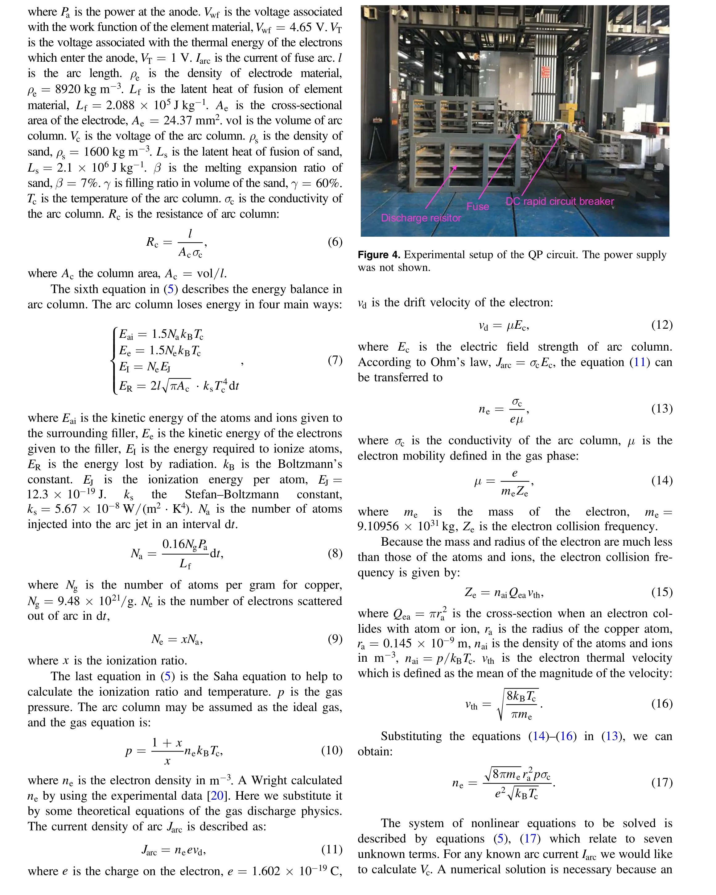
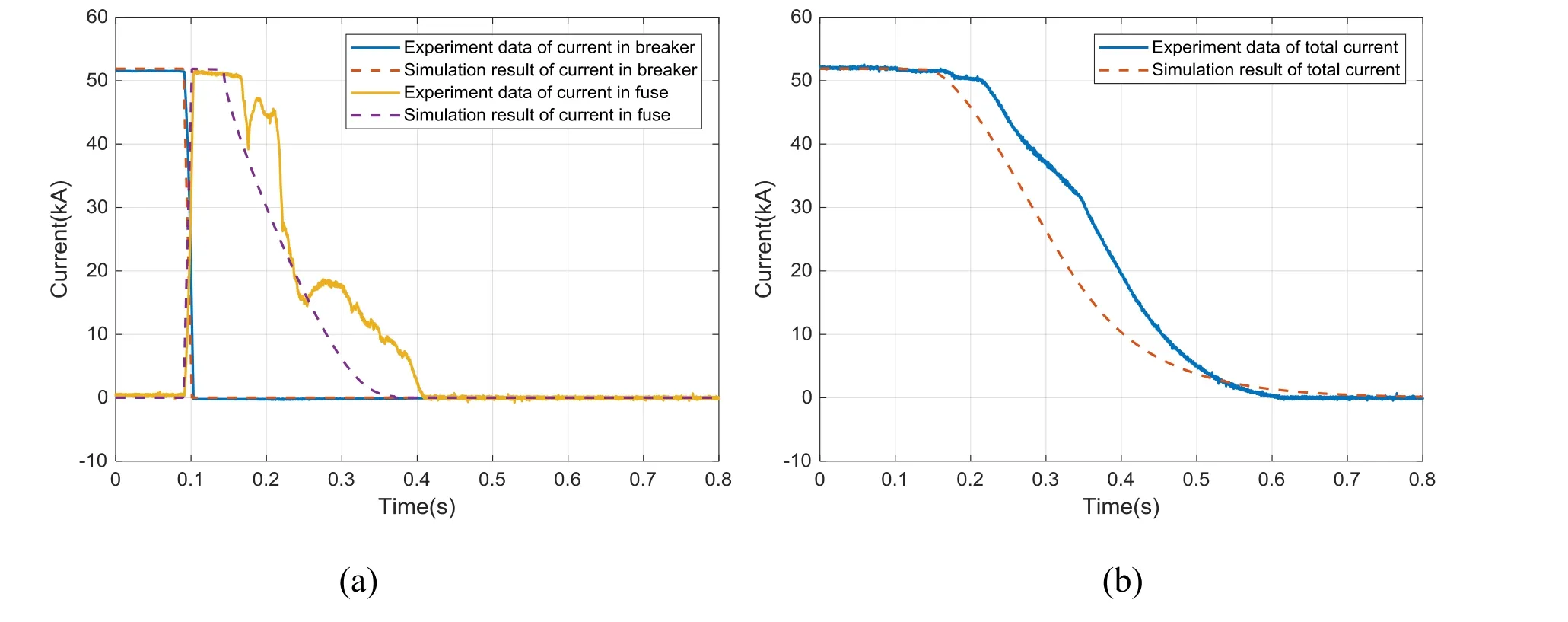
Figure 5.Simulation results of the breaker branch, the fuse branch and the total current compared to experiment data with the shot number 93716 at 52 kA.
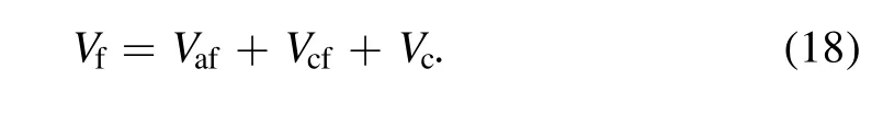
(1) Stage I: commutation process of the current from the breaker branch to the fuse branch.algebraic solution is not possible even with approximations.Any general-purpose nonlinear minimization method is suitable for solving the system. Here the arc model is coded in Matlab using fminsearch function. Then the voltage drop of the fuse in arc period can be described as
2.3.Stage III:process of the current decrease in the discharge resistor
After the current in the fuse branch decreases to zero, the arc is extinguished and the fuse branch turns off. The main circuit current flows into the discharge resistor branch. Then the energy stored in the coil dissipates by the resistor until the coil current eventually drops to zero.The value of the main circuit currentIis given by:
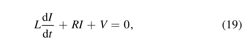
whereLis the inductance of load.Ris the circuit resistance,R≈Rqat stage III.Vis the voltage drop of the external circuit, =V1 V.
3. Results of the simulation and experiment
Combining the model described above,an integrated model is developed. All calculation was coded in Matlab. The differential equations were solved by the Runge–Kutta method. In order to verify the effectiveness of the presented model, an engineering experiment with the topology shown in figure 1 has been implemented to evaluate the simulation results. The photo of the experimental setup is shown in figure 4.The twoquadrant converters not shown in the photo are connected in series with the QP circuit and the dummy load (5 mH).
In order to facilitate the visual comparison of the simulated and the experimental data, the experimental data were transferred from TeamPlus and plotted in Matlab. Then the simulation results of current and voltage in each branch comparing to experiment data with the shot number 93716 are shown in figures 5 and 6.
As can be seen, the computed value of the breaker current has enough accuracy compared to the experiment data.The presented model in stage II cannot simulate the current vibration and the overvoltage of the fuse arc. This phenomenon could be attributed to the instability of the fuse arc and the insufficient cooling of the sand.Furthermore,as the initial length of the fuse arc is hard to determine, the computing of the initial arc voltage may lead to a large error compared with the experiment data. However, the simulated current and voltage have the same tendency with the experiment data,and the computed time that current decreasing to zero is close to the experiment results. Therefore, the effectiveness of the proposed integrated model has been verified. The main error comes from the manufacturing process of the fuse,the sensor error, the circuit parameter error, etc.
4. Conclusions
This paper presents an analytical model to investigate the commutation process in the QP circuit.The model covers the whole commutation process. It consists of the QP circuit equations,the breaker arc model,and the detailed fuse model.Then an engineering experiment is carried out to verify the effectiveness of the presented model. The simulated current and voltage have the same tendency with the experiment data,and the computed time that current decreasing to zero is close to the experiment results. Further work may concentrate on the improvement of the fuse design based on the presented model.
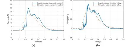
Figure 6. Simulation results of the resistor branch compared to experiment data with the shot number 93716 at 52 kA.
Acknowledgments
The authors would like to thank all the members of the team for their helpful discussion and suggestion. This work relies on the great effort which our colleagues made on the manufacturing and experimenting of the designed model.
猜你喜欢
杂志排行

Plasma Science and Technology的其它文章
- Sensitivity of two drug-resistant bacteria to low-temperature air plasma in catheterassociated urinary tract infections under different environments
- First experimental results of intrinsic torque on EAST
- Gas pressure effect on plasma transport in a magnetic-filtered radio-frequency plasma source
- Design of a variable frequency comb reflectometer system for the ASDEX Upgrade tokamak
- Optimization of plasma-processed air (PPA)inactivation of Escherichia coli in button mushrooms for extending the shelf life by response surface methodology
- Reconstruction of hollow areas in density profiles from frequency swept reflectometry