Gas pressure effect on plasma transport in a magnetic-filtered radio-frequency plasma source
2020-06-28OUDINIALIMTADJINEandBENDIB
N OUDINI , M M ALIM, R TADJINE and A BENDIB
1 Laboratoire des Plasmas de Décharges,Centre de Développement des Technologies Avancées,Cité du 20 Aout BP 17 Baba Hassen, 16081 Algiers, Algeria
2 Laboratoire d’Electronique Quantique,Faculté de Physique,USTHB,El Alia BP 32,Bab Ezzouar 16111,Algiers, Algeria
Abstract Volume negative ion production relies on a magnetic filter(MF),where the plasma downstream of the MF is characterized by a strip-like pattern that consists of a bright and dense plasma region. In this work, we study, in a radio-frequency plasma source, the effects of operating pressure on this strip. This investigation, conducted using a Langmuir probe, shows that the plasma uniformity might be controlled through the gas pressure. Moreover, the operating pressure determines on which hemi-cylinder (side of magnetic field lines) the strip forms. This side inversion of the high-density plasma hemi-cylinder is due to an inversion of an ambipolar electric field that changes the E×B drift direction.
Keywords: magnetic filter, radio-frequency plasma source, Langmuir probe, E × B drift,ambipolar electric field(Some figures may appear in colour only in the online journal)
1. Introduction
An external magnetic field is used in several low-temperature plasma sources,such as a magnetron[1–3],end-Hall ion source[4–6] and Hall-effect thruster [6–8]. These plasma sources are involved in several applications, such as thin film deposition[9, 10], magnetic enhanced reactive ion etching (MERIE)[11–14] and electric propulsion [15]. Due to magnetic drift,plasma sources involving an external magnetic field generally have a cylindrical configuration with an electric field oriented along the axial direction and a magnetic field oriented along the radial direction,or the opposite.Thus,the E×B drift is closed along the azimuthal direction.These latter sources are generally referred to as closed-drift plasma sources [16]. However, the magnetic drift is, in some sources, obstructed by the source walls.The PEGASES(Plasma propulsion with Electronegative GASES)thruster[17]and ITER-NBI(neutral beam injector for the ITER thermonuclear fusion reactor) [18] are typical examples of obstructed-drift sources. The effect of a magnetic filter(MF) on helicon source operation is also a subject of interest,and it has been demonstrated that the presence of the MF has a significant effect on electron heating upstream of it [19].
Hagelaar and Oudini [20] investigated, numerically,plasma transport across magnetic field lines in low-temperature plasma sources.Their results show that,due to magnetic drifts,namely E×B drift and diamagnetic drift, i.e. ∇ (neTe)×B,(where E and B represent electric and magnetic fields,Teis the electron temperature in energy units and neis electron density),the electron transport is enhanced across magnetic field lines at the wall vicinity.As a consequence,the MF is characterized by a current leakage located at the aforesaid region. This observation was confirmed later, numerically by Fubiani et al [21]and,experimentally by Gaboriau et al[22].Although magnetic field gradient effects on electron transport across the MF are reported in several works [20–22], Oudini et al [23] recently demonstrated that the latter gradient,i.e.magnetic mirror force,significantly affects the plasma spatial distribution.Their results show that, at the MF plane, the plasma density decreases with the increase in magnetic field strength [23]. Moreover, Gerst et al[24]observed the formation of strip-like patterns,i.e.bright strip, a few centimeters downstream from the MF plane. They concluded that the axial components of the pressure force and electric field lead to the formation of the observed pattern.
In this work,we study experimentally the strip formation in a cylindrical radio-frequency inductively coupled plasma (RFICP)plasma source operating with argon.This study relies on the measurement of the azimuthal distribution of plasma properties via a Langmuir probe (LP). Our measurements show that the operating pressure plays an important role in the strip formation.
2. Experimental setup
Figure 1 shows,schematically,a description of our experimental setup. This latter involves a cylindrical plasma source. In this source, the dielectric discharge chamber is made up by a borosilicate glass cylinder of which the diameter is 10 cm. An antenna is rolled around the aforesaid cylinder making six turns.A flow of cooled water circulates within this antenna to evacuate heat. Argon gas is injected into the discharge chamber from one end of the cylindrical borosilicate tube. The gas flow rate of injected argon is controlled by means of a needle valve.The gas pressure within the discharge chamber is controlled via a pumping system,as illustrated in figure 1.This system combines the use of a rotary pump and a diffusion pump. The plasma is ignited and sustained by circulating a current within the antenna.To do so a radio-frequency power supply, operating at 13.56 MHz, is connected to the antenna through an L-type matching box. The undesirable propagation of electromagnetic radiation propagation in the laboratory is impeded by the use of a Faraday shield.
Permanent magnets are used to generate an external magnetic field that plays, in our experiment, the role of an MF. These magnets, rare earth neodymium permanent magnets,are cylindrical with a height and diameter of 1 cm.These magnets, 14 in total, are separated into two groups of seven and placed outside the cylindrical plasma chamber at diametrically opposite positions. The two magnet groups are placed,in diametrically opposite positions,perpendicularly to the plasma source wall. The poles of the aforesaid magnets are placed in a geometrical configuration such that each magnetic field line crosses the 14 used magnets (see figure 1(b)).A gap of 5 cm separates the grounded end of the antenna and the MF plane, i.e. the plan containing the magnets.At 6 cm away from the MF plane,an LP is placed at the radial position 3.5 cm.It is important to mention that the LP is fixed,while the MF is able to be rotated manually in the plane(Oy, Oz). This allows us to investigate different azimuthal positions of the generated magnetic field. The angle formed between the line containing the magnets and Oy axis, i.e. the axis defined by the LP and cylinder symmetry axis, ranges from 0°to 360°.Note that the aforesaid angle is considered in the following as the azimuthal position diagnosed by the probe. The reference of the azimuthal position, i.e. 0°, is chosen arbitrarily and is intercepted by the central magnetic field line of the MF. This means that for the azimuthal position corresponding to 0° the magnetic field lines are oriented mainly parallel or antiparallel to the Oy axis (see figure 1(a)); the same applies to the azimuthal position corresponding to 180°.
The MF magnetic field strength profile along the plasma source axis (Ox direction) is shown in figure 2. The position x=0 refers to the MF axial position. The magnetic field profile on the plasma source axis is characterized by a maximum value of 230 Gauss and a full width at half maximum of about 10 cm.
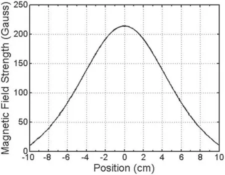
Figure 2. Spatial distribution of the magnetic field intensity, in Gauss, along the source axis.
The experimental protocol is summarized as follows.The chamber is first pumped-down to a high vacuum. Then, the argon flow rate is injected to ensure an operating pressure that is monitored through a Pirani gauge. Once the pressure is stabilized, the RF generator is turned ON, and the matching network is adapted to limit as much as possible the reflected power. Thereafter, the plasma is sustained for a few minutes before starting the measurements, to get rid of any plasma property deviations that might be induced by temperature increases in the plasma chamber walls or antenna.Finally,the plasma properties are diagnosed through an LP for several MF positions. The used probe has a length and a diameter corresponding to 1 cm and 0.2 mm, respectively. The LP is compensated with respect to 13.56 MHz frequency plasma potential oscillations and its harmonics.
Figure 1(c) shows a picture of the plasma generated by the described magnetic-filtered radio-frequency discharge operating in air. To better highlight the strip-like formation,the MF is moved to a location that is 12 cm away from the antenna grounded end. This picture shows the asymmetry introduced by the external magnetic field.
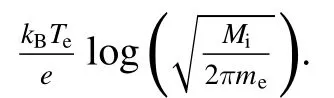
To deduce the plasma properties from the collected current–voltage (IV) characteristics, we fit the collected data.Indeed, assuming that the electron distribution function is Maxwellian,the electron contribution to the probe current,i.e.Ie, is summarized by
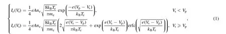
where e is the elementary electric charge, A is the probe tip surface, neis the electron density, kBis the Boltzmann constant, Teis the electron temperature, meis the electron mass, Vpis the plasma potential and Vsis the probe bias.
Also, we assume that positive ion contribution to the probe current, i.e. I+, corresponds to
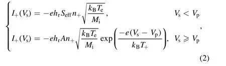
where hr=0.6 is the edge-to-center ratio, Seffis the probe collection area, T+is the positive ion temperature and Miis the positive ion mass.
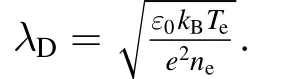
To estimate the collection area we use the following formula given in [25].

Equations(1)–(2)are used to fit the collected data,with a constraint on quasi-neutrality, i.e. we impose n+=ne, to deduce the plasma potential Vp, electron temperature Teand electron density. Numerous techniques devoted to LP data analysis are discussed in [26–29].
We would like to mention that equations (1)–(3) completely neglect the effect of the magnetic field on the probe current.This could be justified as follows.The magnetic field strength in the investigated region, i.e. 6 cm away from the MF plane, drops to ~80 Gauss. For this magnetic field strength, and for the measured electron temperatures, i.e.about 5 eV (see figure 6), the Larmor radius is about 1 mm that is five times larger than the LP radius. We would like to recall that Laframboise and Rubinstein[30]demonstrated that the magnetic field slightly affects the probe current when the probe radius is narrower than the Larmor radius, unless the magnetic field lines are strictly parallel to the probe tip (see

Figure 3. Azimuthal distribution of the ion saturation current, for a 100 W discharge, measured 6 cm away from the MF position at a radial position r=3.5 cm, for a pressure of 30 mTorr.
[30]). We would like to mention that the magnetic field, in view of our experimental configuration (see figure 1), intercepts the LP tip obliquely.
We would like to mention that we studied, in [23], the plasma properties at the MF filter location. In the aforesaid work, our findings showed that plasma properties are significantly affected by the magnetic field gradient in the vicinity of the magnets used to generate the MF.For instance,due to the magnetic mirror force, plasma density decreases with the increase (tightening) in magnetic field strength (lines).
3. Results and discussion
Figure 3 shows the measured probe current for a bias of-20 V as a function of the azimuthal position for a probe located 6 cm away from the MF plane, and at a radical position corresponding to 3.5 cm for an operating pressure of 30 mTorr and a discharge of 100 W. In view of the probe bias,we consider that the measured current corresponds to the ion saturation current. Figure 3 shows that the ion saturation current is greater for the hemi-cylinder defined by the azimuthal position [180°, 360°] than what is measured for the azimuthal position between [0°, 180°]. This result is in good agreement with the observation made by Gerst et al [24].Indeed, Gerst et al [24] observed the formation of strip-like patterns, i.e. a bright strip characterized by high plasma density, a few centimeters downstream from the MF plane.According to Gerst et al [24] the formation of the aforesaid pattern is due to the presence of forces pulling and/or pushing electrons in a preferential direction towards the plasma source wall.As a consequence of these forces,the spatial distribution of the plasma density is not axisymmetric and,therefore,one hemi-cylinder is denser than the other.
We would like to emphasize that the ion saturation current azimuthal profile is not affected at all by the magnetic field,since the ion Larmor radius is infinitely greater than the probe radius [30].
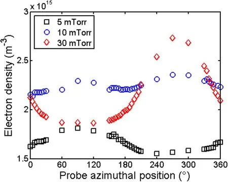
Figure 4.Azimuthal distribution of plasma density, for a 100 W discharge, measured 6 cm away from the MF position at a radial position r=3.5 cm, for different pressures.
Figure 4 shows the azimuthal distribution of plasma density,for a 100 W discharge,measured 6 cm away from the MF at a radial position corresponding to 3.5 cm for different pressures: (i) 5 mTorr, (ii) 10 mTorr and (iii) 30 mTorr. The plasma density,averaged over the azimuthal position,is about 1.5×10¹⁵m-3for a pressure of 5 mTorr, and increases to about 2.2×10¹⁵m-3for pressures of 10 mTorr and 30 mTorr. The density profiles are characterized by a significant gradient along the azimuthal direction. This gradient is attributed, according to the literature [20, 21, 24], to a combination of E×B and diamagnetic drifts that push the plasma towards the plasma source’s walls. However, we notice that for 5 mTorr, the plasma density at the hemicylinder defined by the azimuthal position between 0° and 180°is greater than the second hemi-cylinder.In contrast,for 30 mTorr we observe the opposite, i.e. the plasma density at the azimuthal position between 0° and 180° is smaller than what is measured at the azimuthal position between 180°and 360°. While for 10 mTorr, the plasma density profile is more or less flat and symmetric, in comparison to the other pressures.
We would like to mention that the spatial distribution of plasma density might be affected by the local production of electron–ion pairs through gas ionization.Indeed,the electron temperature in the diagnosed region, for the investigated experimental conditions,is about 5 to 8 eV.Therefore,a nonmarginal part of the electron has enough energy to ionize the gas. Furthermore, when electrons are magnetized, i.e. when the electron Larmor radius is much smaller than the plasma source diameter and the electron mean free path, the electron trajectory wraps around magnetic field lines allowing the electron to travel, within the magnetized region, a distance that is much greater than the dimension of this latter region.This allows ionization to be a non-marginal process within the MF, even if the magnetized region is smaller than the ionization mean free path.
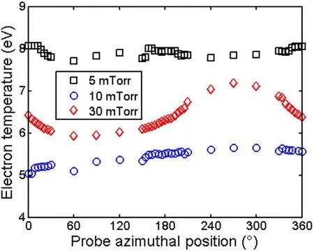
Figure 6. Azimuthal distribution of the electron temperature measured, for a 100 W discharge, 6 cm away from the MF position at a radial position r=3.5 cm, for different pressures.
4. Conclusion
In this work, electron transport across an MF is investigated experimentally in a radio-frequency plasma source.This study is conducted by analyzing the plasma properties, i.e. electron density and temperature and plasma potential,using a cylindrical LP.The azimuthal profile of the plasma density shows an important gradient due to the formation of a strip-like pattern.This pattern manifests by a hemi-cylinder that is clearly denser than the other one. This unbalance between plasma densities measured at the two hemi-cylinders is due to magnetic drift. Therefore, plasma density uniformity is strongly affected by the operating pressure,since the magnitude of the ambipolar electric field can be controlled through the operating pressure value. Indeed, the plasma density gradient can be limited by choosing an operating pressure that limits the ambipolar electric field magnitude.Moreover, the operating pressure might be used to control the plasma density uniformity. Both electron temperature and plasma density azimuthal profiles are characterized by hydrodynamic gradients.These gradients may play a significant role in electron transport that has not been quantified in this work.
ORCID iDs
N OUDINI https://orcid.org/0000-0003-3065-5254
杂志排行

Plasma Science and Technology的其它文章
- Sensitivity of two drug-resistant bacteria to low-temperature air plasma in catheterassociated urinary tract infections under different environments
- First experimental results of intrinsic torque on EAST
- Design of a variable frequency comb reflectometer system for the ASDEX Upgrade tokamak
- Optimization of plasma-processed air (PPA)inactivation of Escherichia coli in button mushrooms for extending the shelf life by response surface methodology
- Reconstruction of hollow areas in density profiles from frequency swept reflectometry
- Fullwave Doppler reflectometry simulations for density turbulence spectra in ASDEX Upgrade using GENE and IPF-FD3D