Modelling and Backstepping Motion Control of the Aircraft Skin Inspection Robot
2019-07-23,
,
Abstract: Aircraft skin health concerns whether the aircraft can fly safely. In this paper,an improved mechanical structure of the aircraft skin inspection robot was introduced.Considering that the aircraft skin surface is a curved environment, we assume that the curved environment is equivalent to an inclined plane with a change in inclination. Based on this assumption, the Cartesian dynamics model of the robot is established using the Lagrange method. In order to control the robot's movement position accurately, a position backstepping control scheme for the aircraft skin inspection robot was presented.According to the dynamic model and taking into account the problems faced by the robot during its movement, a position constrained controller of the aircraft skin inspection robot is designed using the barrier Lyapunov function. Aiming at the disturbances in the robot, we adopt a fuzzy system to approximate the unknown dynamics related with system states. Finally, the simulation results of the designed position constrained controller were compared with the sliding mode controller, and prove the validity of the position constrained controller.
Keywords: Aircraft skin inspection robot, dynamics modelling, backstepping control,fuzzy system, barrier lyapunov function, motion control.
1 Introduction
Today, the health inspection of the aircraft skin is mainly done by humans. The inspection efficiency is low, the assessment of the test results is not standard, and it is greatly affected by human factors. A variety of wall-climbing robots are designed to accomplish some tasks. In Apostolescu et al. [Apostolescu, Alexandrescu, Ionascu et al.(2011)], a climbing robot using the electro-pneumatically vacuum cups was designed. In Miyake et al. [Miyake, Ishihara, Shoji et al. (2006)], a small-size and light weight window cleaning robot was developed, the prototype robot consists of two driven wheels and an active suction cup. In Nagakubo et al. [Nagakubo and Hirose (1994)], a kind of wall climbing robot was designed with a gecko-like structure by observing the gecko climbing wall behavior. In Rosa et al. [Rosa, Messina, Muscato et al. (2002)], a type of low-cost climbing robot was proposed which can climb cylindrical painted iron surfaces using eight suction cups, the robot carries an ultrasonic probe equipment to evaluate the integrity of the metal in the inspection of storage tanks.
In order to solve the problems of suction and motion for wall-climbing robots, many useful control strategies have been proposed. In Wettach et al. [Wettach, Hillenbrand and Berns (2006)], the basic thermodynamic model was presented, which was necessary to describe the changes of the pressure under robot motion condition. Based on this model, a controller of vacuum chambers was designed to adjust the chambers pressure. In Yong et al. [Yong, Wang, Fang et al. (2007)], based on the multiple-model adaptive estimation and the Boolean logic reasoning, an approach to fault detection and identification in suction foot control of a climbing robot was presented. In Zhang et al. [Zhang, Zhang and Zong (2008)], a new pneumatic climbing robot was presented to satisfy the requirements of glass-wall cleaning. Furthermore, a segment and variable bang-bang controller was developed to implement the precise control of the position servo system for the X cylinder during the sideways movement. In He et al. [He, Li, and Chen (2017)], a comprehensive survey of the recent development of the human-centered intelligent robot was provided, and the issues and challenges in the field were discussed.
In recent years, researches on intelligent control strategies of robots under input or output constrains have been conducted in-depth. In He et al. [He, Ge, Li et al. (2017); He, Dong and Sun (2015)], some control strategies for some articulated robots and affine nonlinear systems were designed when the systems are subjected to external disturbances and output constraint. In Chen et al. [Chen, Ge and Ren (2011)], an adaptive tracking control method was proposed for a class uncertain multiple input and multiple output nonlinear systems with input constraint. In Ren et al. [Ren, Ge, Tee et al. (2010)], aiming at output feedback nonlinear systems in the presence of unknown functions, a class of control strategies were presented by using adaptive neural network and Backstepping technique.In Li et al. [Li, Li and Jing (2014)], a novel indirect adaptive fuzzy controller for a class of uncertain nonlinear systems with input and output constrains was proposed by using a barrier Lyapunov function and an auxiliary design system to solve input and output constraints. In Chen et al. [Chen, Ge, and How (2010)], the author proposed a robust adaptive neural network control strategy for a class of uncertain multi-input and multioutput nonlinear systems with input nonlinearities. Niu et al. [Niu and Zhao (2013); Niu,Liu, Zong et al. (2017)] investigated the control strategies under output constraint for switching systems and time-varying output constraint system. Ngo et al. [Ngo, Mahony and Jiang (2005); Li, Li, Liu et al. (2017)] dealt with a class of control problems for nonlinear multi-input and multi-output systems with full state constraints.
In this paper, we mainly study the motion control of the inspection robot on the surface of the aircraft skin. Considering the chattering in the sliding mode controller, the robot movement is restricted by the work environment, on the one hand the chattering will cause a violent change in the robot's adsorption force, which will lead to the drastic change of the robot's adsorption force and cause the robot to fall off because of the lack of enough adsorption force. On the other hand, the inaccurate position control of the robot can cause the robot legs touch the surface of the aircraft skin, and then affect the normal motion of the robot. It may cause the robot breaks down or slides directly from the surface of the plane. So we must avoid the robot legs touching the surface of the aircraft skin. Inspired by the above researches, we design a position controller based on the backstepping control with output constraint.
This paper is organized as follows. Section 2 describes the structure of the aircraft skin inspection robot, and Section 3 analyzes the dynamics of the inspection robot. In Section 4, the backstepping control method of the robot is designed by using a barrier Lyapunov function, and the fuzzy system-based adaptive method is used to approximate the unknown dynamics related with system states. Then, the stability of the closed-loop of the robot system is proved by the constructed Lyapunov function. Simulation results are given in Section 5.
2 The structure of the aircraft skin inspection robot
The aircraft skin health inspection robot with dual-frame is shown in Fig. 1. The robot can absorb on the aircraft fuselage using negative pressure. The robot can provide a load of about 15Kg that is enough to support the body and keep stability during inspection.There are four layers in the robot‘s structure. The first and fourth layers of the robot are the outer frame and inner frame, two servomotors and a speed reducer are installed so that the two frames can rotate. The servomotor of the outer frame is used to drive the rotating movement of the inner frame, and the servomotor of the inner frame is used to drive the rotating movement of the outer frame. The second layer of the robot is a mechanism for the robot to achieve pitch attitude adjustment. The purpose is to enable the robot to adapt the surface curvature of the aircraft skin during movement. The third layer is the sliding layer of the robot. A sliding servomotor is used to drive the ball screw to generate translational motion. The inner and outer frames are respectively installed with four mechanical legs, and the legs are connected with vacuum suction cups, so that the robot can adsorb on the surface of the aircraft skin.

Figure 1: Aircraft skin inspection robot with double frame
3 Dynamic modelling
Fig. 2 gives an improved structure of the aircraft skin inspection robot with double frame.The following discussion will focus on the movement of the robot on an inclined plane with a dip angle α.

Figure 2: Structure of the robot
In Fig. 2, O - XYZ is the global coordinate system,is the body coordination system.1O is selected at the point B of the robot. G is the gravity of the robot. Point A is selected as the reference point of position and velocity. r is the horizontal distance between point A and the rotation servomotor axis of the outer frame.1r is the distance from point A to the fixed end of the ball screw.sτ is the torque of the sliding servomotor acting on the ball screw, wsis the angular velocity of the motor driving the ball screw,andsθ is the rotation angle of the ball screw. The rotation of the ball screw drives the horizontal movement of the sliding layer.pτ is the torque produced by a pitch motor,pω is the angular velocity of the pitch motor, and thepθ is the angle between inner frame and outer frame which is produced by the pitch motor,rτ is the rotation torque produced by the rotating motor,rω is the rotational angular velocity, and therθ is the angle of rotation axis.are the support forces.are the absorption forces. The driving system of the robot is shown in Fig. 3.

Figure 3: The driving system of the robot
3.1 Dynamic model in joint space
In Fig. 3, the moment of inertia of the inner frame is calculated by

where I is the inertia of the inner frame ,1m is the mass of the sliding motion body, L is total sliding distance,1y is the horizontal sliding distance of the inner frame, and λ is the equivalent mass density of the rigid body, which satisfies

The kinetic model is derived by the Lagrange formula as follows:
Kinetic energy of the inner frame is

where r = kθs,k is the helical pitch of the ball screw.
The potential energy of the moving inner frame is

The Lagrange function of the inner frame can be written as:

Therefore, the dynamics equation of the inner frame is given by:
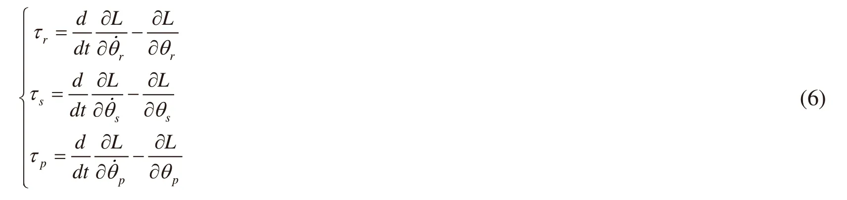
We can obtain the dynamic equation of the inner frame in joint space as follows:


3.2 Dynamic model in Cartesian space
In Fig. 3, the position of the point A in the coordinate systemis expressed as:

From (8), we can obtain:

According to the above relationship, we can obtain:
where the range of θpis set assuch that the Jacobian matrix is full rank.In the Cartesian space, when the Jacobian matrix is full rank, the virtual control forceis expressed as


From Eq. (12), we can obtain:

According to Eq. (12) and Eq. (13), we can obtain:

Substituting Eq. (12) and Eq. (14) into Eq. (7), we can obtain:

Then, Eq. (15) can be expressed as:

Multiplying both sides of (15) byyields

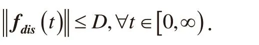
According to Eq. (11) and considering the disturbance, we can obtain the following Cartesian dynamics model.

where
Eq. (18) has the following properties:
The property1: Mx(q) isa positive definite symmetric matrix.
4 Backstepping position controller design using barrier lyapunov function
Thus the dynamics model (18) can be transformed into a state-space expression as

The robot position error is defined as:

The auxiliary variable error is defined as:

where α is the virtual control.
The derivative of e2is expressed as:

In order to ensure that the legs do not touch the aircraft skin during the motion of the robot, we adopt the barrier Lyapunov function to restrain the trajectory tracking error.
The barrier Lyapunov function is selected as follows:

where bi> 0is a small constant.
The derivative of1V is written as:

The virtual controliα is selected as follows:

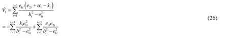
where ki> 0.
Substituting Eq. (25) into Eq. (24) yields:
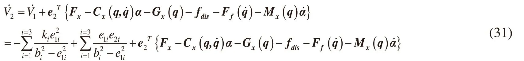
The second-order Lyapunov function is selected as

The derivative of V2is obtained as:

Substituting Eq. (21) into Eq. (28), we can obtain:

Substituting Eq. (19) and Eq. (21) into Eq. (29) yields:

Based on the property 2 and Eq. (26), we can obtain:
If x1isand … and xnis,Then y is Bj. j =1 ,2,...,N
where Fijand Bjare fuzzy sets of membership functionsandrespectively, N is the number of rules.
Then, the output of the fuzzy system can be defined as


Based on the above method of the fuzzy system, the approximation of the unknown parameters can be designed as follows:

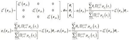
The membership function is selected as

Define the optimal approximation parameter θ*and the optimal approximation Φ*for a given arbitrarily small constantwe have
Then we design the controller as following

where K2>0 is a diagonal matrix, l >0 is a constant.
Substituting Eq. (35) into Eq. (31), we can obtain


Lyapunov function is selected as:

The derivative of V3is written as:

Substituting Eq. (36) into Eq. (39), we can obtain:

Substituting the adaptive parameter control law Eq. (37) into Eq. (40), we can obtain:
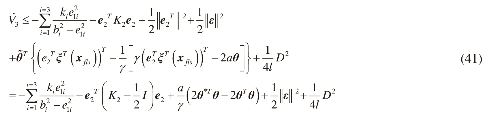

Substituting the Eq. (42) into the Eq. (41) yields:
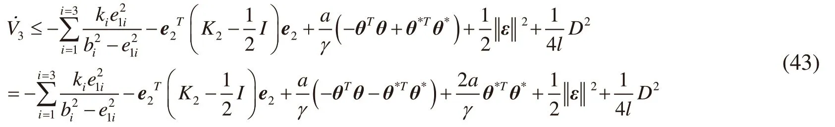


Substituting Eq. (45) into Eq. (43) and using Lemma1, we have:

In order to ensure ρ > 0,select,where λminrepresents the minimum eigenvalue of the matrix, λmaxrepresents the maximum eigenvalue of the matrix.Multiplying the left and right sides of Eq. (46) by eρt, t≥ 0, we can obtain:

Then take integrals on both sides:

Define:

According to the definition of V3and Eqs. (48)-(49),we can obtain:

Therefore, the errors of the closed-loop systemconverge automatically to the compact sets,where
Lemma 2 [Slotine and Li (1991)]: (Barbalat's lemma) A Lyapunov function candidate V (x) is bounded if the initial condition V (0) is bounded, V (x) is positive definite and continuous, and if,where ρ > 0and C > 0.
From Lemma 2, we know that both the tracking errors of system states and estimation errors of uncertain parameters as well as unknown disturbance are bounded.According towe can calculate the actual control torque. In a similar way,we can derive the dynamic equation of the outer frame and design the position controller.
5 Simulation
In this section, the simulation was carried out to illustrate the effectiveness of the proposed control scheme for the inspection robot with double frame.
In the simulation, the parameters of the inner frame for the robot are chosen as follows m1= 6kg, r1= 0.05m, L = 0.2m, α = π/ 6, k= 1.
The parameters of the controller are chosen as

The friction force and external disturbances are given by
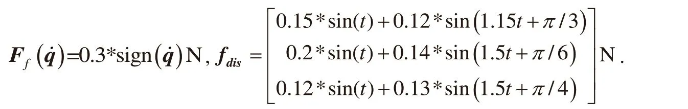
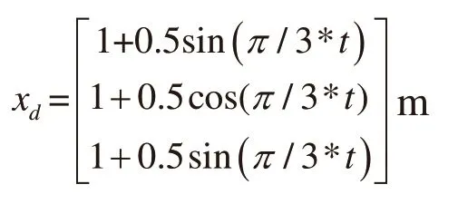
The position tracking curves of the aircraft skin inspection robot are shown in Fig. 4. Fig.5 shows the tracking errors of position by using the sliding mode control and the backstepping control. As shown in Fig. 5, we know that there are lager errors by using sliding mode control, and it will cause the robot legs touch the surface of the aircraft skin.By using the backstepping control, there is a very small error in the system. Therefore,the latter is more suitable as a motion controller for the aircraft skin inspection robot. Fig.6 shows the motor driving torque with the sliding mode control and the backstepping control. In Fig. 6, we know that sliding mode controller has great shaking, this will further affect the stability of adsorption. But the backstepping control does not cause shaking phenomenon. Therefore, the backstepping controller can ensure the control torque is relatively smooth during the movement of the robot. Fig. 7 shows the approximation of unknown dynamics related with system states. Tab. 1 shows the comparison of the position tracking errors between sliding mode control and Backstepping control with output constraint.

Figure 4: Tracking trajectories of the inspection robot
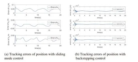
Figure 5: Tracking errors of position

Figure 6: Motor driving torques
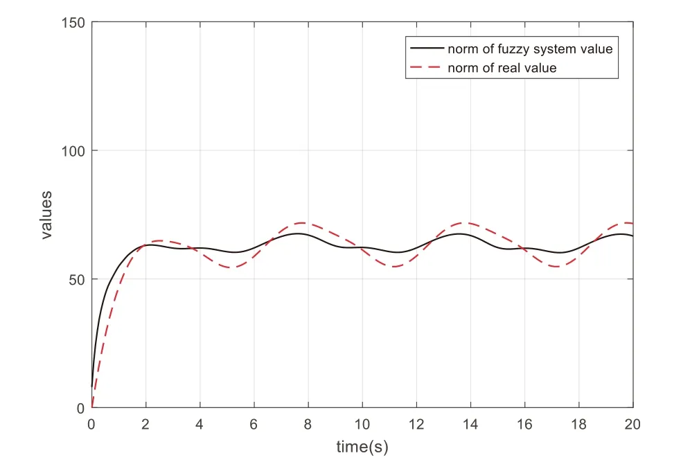
Figure 7: Approximation of the fuzzy system

Table 1: Position tracking errors
6 Conclusion
In this paper, an improved aircraft skin inspection robot was introduced. First, the mechanical structure of the robot was described in detail. Second, the dynamic model of robot in Cartesian space was established and the motion control scheme based on the backstepping method using the barrier Lyapunov function for the aircraft skin inspection robot was designed. Considering the robot movement is restricted by the work environment,the backstepping control method with output constraint is presented. The fuzzy system is adopted to approximate the unknown dynamics related with system states. Finally, the effectiveness of the control method is verified by simulation. Due to using the backstepping control, there is a very small error of trajectory tracking for the robot, and the control torque is relatively smooth during the movement of the robot. Therefore, the smooth motion of the robot can ensure the stability of the adsorption on the surface of aircraft.
Acknowledgement:This work was supported by the National Natural Science Foundation of China (Grant No. 61573185) and JiangSu Scientific Support Program of China (Grant No. BE2010190).
杂志排行

Computer Modeling In Engineering&Sciences的其它文章
- A Hierarchy Distributed-Agents Model for Network Risk Evaluation Based on Deep Learning
- Region-Aware Trace Signal Selection Using Machine Learning Technique for Silicon Validation and Debug
- Blending Basic Shapes By C-Type Splines and Subdivision Scheme
- Equivalence of Ratio and Residual Approaches in the Homotopy Analysis Method and Some Applications in Nonlinear Science and Engineering
- Numerical Validations of the Tangent Linear Model for the Lorenz Equations
- A Multiscale Method for Damage Analysis of Quasi-Brittle Heterogeneous Materials