An indoor positioning system for mobile target tracking based on VLC and IMU fusion
2019-01-17ZouQianXiaWeiweiZhangJingHuangBonanYanFengShenLianfeng
Zou Qian Xia Weiwei Zhang Jing Huang Bonan Yan Feng Shen Lianfeng
(National Mobile Communications Research Laboratory, Southeast University, Nanjing 210096, China)
Abstract:An indoor positioning system (IPS) is designed to realize positioning and tracking of mobile targets, by taking advantages of both the visible light communication (VLC) and inertial measurement unit (IMU). The platform of the IPS is designed, which consists of the light-emitting diode (LED) based transmitter, the receiver and the positioning server. To reduce the impact caused by measurement errors, both inertial sensing data and the received signal strength (RSS) from the VLC are calibrated. Then, a practical propagation model is established to obtain the distance between the transmitter and the receiver from the RSS measurements. Furthermore, a hybrid positioning algorithm is proposed by using the adaptive Kalman filter (AKF) and the weighted least squares (WLS) trilateration to estimate the positions of the mobile targets. Experimental results show that the developed IPS using the proposed hybrid positioning algorithm can extend the localization area of VLC, mitigate the IMU drifts and improve the positioning accuracy of mobile targets.
Key words:indoor positioning system (IPS); visible light communication (VLC); inertial measurement unit (IMU); hybrid positioning algorithm
In recent years, the applications of wireless sensor networks are becoming increasingly essential in our daily life. Location information becomes important in location-based services (LBS) with the popularization of mobile communication and the Internet[1]. The global positioning system (GPS) cannot support indoor positioning due to the blocking of electromagnetic signals and multipath interference. Numerous research and solutions for GPS complementation have emerged in the past decades. Among the radio indoor positioning systems, the system based on visible light communication (VLC) is more accurate than those based on wireless local area networks (WLAN) and radiofrequency identification (RFID), more stable than that based on Bluetooth (BT), and cheaper than that based on ultra-wide band (UWB)[2].
Optical wireless communication has gained much attention, which transmits the data through air using infrared (IR) and VLC[3-4]. Positioning based on VLC is preferred due to no electromagnetism, long lifespan, low cost and no health risks. VLC with a light-emitting diode (LED) has a shorter wave than the radio frequency in reducing multipath effects in an indoor environment. The positioning techniques used in location estimation are based on the geometric properties of triangles including triangulation and trilateration[5]. Since VLC is limited by the field of view, the triangulation method based on the angle of arrival (AOA) is not suitable. The trilateration method based on time of arrival (TOA) or time difference of arrival (TDOA) requires that the transmitter and receiver keep strict synchronization. Therefore, these methods are not applicable for VLC positioning. In this paper, the method based on received signal strength (RSS) is used since it is easy to achieve and can provide better accuracy.
Measurement from the inertial measurement unit (IMU) accounts for the relative estimation of position with low cost and reasonable accuracy. IMU consists of accelerometers, gyroscopes and electronic compasses and it can measure the acceleration and angular velocity[6]. However, IMU has long term drift and is sensitive to initialization of positioning. Hence, it is necessary to enhance the positioning accuracy with calibration and it also needs to be used with the integration of other measurements[7].
There is some research on realizing indoor positioning based on VLC[8-10], which communicates via wired connection in a limited positioning range. As for the IMU positioning system, due to its error-accumulation, it is not reliable enough for indoor positioning independently[11-12]. The indoor environment has many barriers for VLC positioning and the IMU cannot reduce the drifts by itself. To solve the practical problem and take advantages of VLC and IMU, an indoor positioning system (IPS) based on VLC and IMU is developed to extend the localization area of VLC and reduce IMU drifts.
In this paper, an IPS is developed by using the hybrid positioning algorithm, which consists of the LED transmitter, receiver and localization server. Before positioning, the calibration and normalization of VLC RSS and IMU data are conducted. Then, an RSS propagation empirical formula is given to obtain a higher positioning accuracy. A hybrid positioning algorithm is proposed based on the adaptive Kalman filter (AKF) and weighted least squares (WLS) trilateration which fuses the VLC RSS and IMU data together to calculate the positioning solution. The hybrid positioning algorithm is evaluated by using the developed platform with the experimental results.
1 System Description
The IPS shown in Fig.1 consists of three main parts: the LED-based transmitter, receiver and positioning server. The receiver is equipped with an advanced RISC machine (ARM), which collects measurement data and transmits the information to the server. Then, the positioning server applies the hybrid positioning algorithm to estimate and display the positioning results.
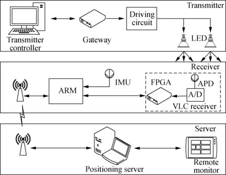
Fig.1 System architecture of the indoor positioning system
1.1 LED-based transmitter and protocol design
The transmitter consists of the controller, gateway and LED transmitter. The controller serves to control and set the parameters of gateway. The gateway is a programmed device of the field programmable gate array (FPGA). It executes controlling instructions and transmits the message to LEDs or to another gateway. The LED transmitter includes the driving circuit and LED. When the gateway receives the controlling commands, it can change its configurations or activate its transmitters.
To ensure a good performance of the VLC system, the on-off keying (OOK) modulation is used at the transmitter due to its low complexity and high transmission rate. The signal is encoded into “0” or “1” by Manchester encoding. All the LEDs transmit their own ID data during their own time slot. The frame structure includes the header, unique identification (UID) of the transmitter, data and tail.
1.2 ARM-based receiver
There are three main parts: the IMU, VLC receiver and ARM in the receiver, as shown in Fig.2. ARM is not only used for data transformation, but also works as a controller and gateway. The VLC RSS and IMU data will be collected by ARM with timestamps, and then ARM sends the data to the next gateway or server. ARM can change the configurations and transmit the feedback message to the server.
IMU consists of a three-axis accelerometer and a three-axis gyroscope (magnetometer sensors are often unreliable), which has been generally aligned during manufacturing and placed horizontally on the mobile target.The coordinate system on the grid body of IMU is assigned to be the body frame, and the inertial navigation coordinate system is assigned to be the global frame correspondingly. The VLC receiver with avalanche photodiode (APD) and analog-to-digital (AD) converts the optical signal into an electrical signal and then obtains the RSS and the ID data. The RSS measurement and the corresponding ID will be put into a fixed-length frame and then sent to ARM by FPGA.
1.3 Positioning server
The hybrid positioning algorithm is applied in the server, which is composed of three modules. The network control module plays a significant role in improving the performance of communication and positioning. In this

Fig.2 Framework of the ARM-based receiver
paper, only one receiver is considered, so the details of this function will not be discussed here. The data storage and processing module reads the raw data package, and it saves the necessary data and final positioning solutions into the database. After the position solution is obtained, the module can send the real-time position to the display module.
2 Measurement Preprocessing
In this section, the measurement calibration is described in detail. The bias and drifts of calibration formula will be updated to improve the accuracy of the measured data. Then, a propagation empirical formula is proposed to calculate the distances from reference points to the mobile target based on RSS.
2.1 Measurement calibration

(1)
(2)

In this system, the RSS is denoted as the received power of the electrical signal. Before the distance calculation, the calibration procedure is required. A set of RSS={RSS1,…,RSSi,…,RSSC} are collected with known horizontal distancesr={r1,…,ri,…,rC}.Cis the number of the measured RSS. The calibration formula of RSSiis given as
ui=U(RSSi)=G·(RSSi+bj)+nj
(3)

2.2 RSS propagation model
According to the Lambertian law[15], the receive power of the electrical signal is calculated considering the irradiance angle, the effective area of the receiver photodiode, the filter gain and concentrator gain. The Lambertian law requires that the medium must be homogeneous and the incident radiation must be strictly parallel, which are difficult to fulfill in a practical environment. However, there is a snoot attached to the LED to increase the effective luminous intensity[16]. Therefore, the real indoor positioning system cannot meet the strict environment requirements of Lambertian law.
To obtain a more accurate horizontal distance from the receiver to LEDs, a novel empirical formula is given with the data RSS and horizontal distancer. With the vertical receiver and horizontal transmitter, the measurements of VLC RSS and horizontal distance are collected to fit the empirical formula. The height of LEDs is 2.25 m, and the horizontal distanceriis calculated by the empirical formulaR(ui) with normalized RSSuifrom Eq.(3) which is shown as
(4)
wherep0=58,p1=-76,p2=-11,p3=116, andp4=-84. The fitting precision is high and the empirical formula is reliable in this IPS. Finally, the comparison between the empirical formula and Lambertian law is shown in Fig.3. It is clear that the empirical formula is closer to the real data than the traditional model.

Fig.3 Comparison between empirical formula and Lambertian law
The normalization is required during positioning, andGandbjin Eq.(3) are shown as
(5)
(6)
whereU(RSSi)0=U(RSSi|bj=0) andR(·) is the RSS propagation function the same as that in Eq.(4).
Before positioning, the calibration parametersbac,bav,Gandbjcan be calculated to calibrate the measurements before the hybrid positioning algorithm is used. During positioning, the calibration parameters are updated by Eq.(5) and Eq.(6).
3 Hybrid Positioning Algorithm
The receiver placed on the mobile target is required to start under the illumination range of VLC to obtain an initial position. First, the measurements of acceleration, angular velocity and RSS are calibrated. Then, the distance from the receiver to the LED can be calculated by the empirical formula, and the coordinate of the mobile target can be given by the proposed algorithm.
3.1 AKF with dynamic model
Since the calculation of velocityvkand yaw angleαkof the mobile target are modeled by linear Gaussian noise, the Kalman filter is adopted to obtain a higher accuracy with a lower computational complexity. The prediction process and measuring process are represented as
xk=Axk-1+Wk
(7)
zk=Hxk+Nk
(8)
wherekis the discrete-time tracking filter’s time-index for positioning, and the state vectorxkand the measurement vectorzkare defined as
(9)
(10)
(11)

(12)
WkandNk[17]are the noise vectors in the prediction process and observed process, which are presented as
Wk=[wv,kwα,kwac,kwav,k]T,Nk=[nac,knav,k]T
(13)

Qk+1=(1-ζk)Qk+ζk[diag(τk)]
(14)
whereζk=(1-p)/(1-pk+1) is the amnestic factor;pis a forgetting factor in the range from 0.95 to 0.995[18];τk=(zk-zk|k+1)(zk-zk|k+1)Tis the residual between the measurement and prediction.
3.2 WLS for trilateration
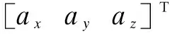
The illustration of the algorithm based on trilateration is shown in Fig.4. Suppose that the corresponding horizontal coordinate (X(i),Y(i)) of LEDiis known, and the horizontal distancerifrom the receiver to LEDican be calculated by Eq.(7).lkis the displacement calculated by IMU data,lk=vkT. When more than one RSS measurement is collected, the coordinate of mobile target (xk,yk) can be calculated as

(15)
Assume that the measurements are influenced by an i.i.d Gaussian random variable with zero mean, the method of ordinary least squares (OLS) used for coordinatesSk=[xkyk]Tis adopted as
ALSS=bLS
(16)
where
To improve the accuracy of coordinateSkin estimation, LS is weighted based on the distances and weightWLSis presented as
(17)
Therefore,the coordinateSkwith the minimum mean squared error ofbLSandALSSkin WLS is described as
(18)
However, in the actual positioning environment, the light from the LED is sheltered or dissipated and the positioning area is limited by the illumination area. As shown in Fig.4, there are three cases when taking the situation that the receiver receives different numbers of RSS measurements into consideration.
Case1When multiple RSS measurements are collected, the calculation is demonstrated as Eqs.(14) to (17).
Case2When only one RSS measurement is collected, the position of mobile targetSkcan be calculated by
(19)
Case3When no RSS measurement is collected, if the initial coordinate is given from the VLC positioning solution, the coordinate of mobile targetSkcan be calculated by
(20)
whereαk-1is the yaw angle at timek-1. Due to the
drifts, the error of results from IMU positioning will increase over time and the initial coordinate is required.
Take four LEDs as an example in Fig.4. Using the triangulation positioning algorithm to calculate the coordinate in Case 1 needs no less than three reliable RSS measurements. Therefore, the available VLC positioning area only includes area 3 and area 4. With the IMU data, the position can be calculated when receiving less than three RSS measurements or even when the mobile target is away from the illumination area. The hybrid positioning algorithm is described in Algorithm 1.
Algorithm1AKF-WLS algorithm for data fusion indoor positioning
Output: Position estimation (xk,yk).
InitializeGvia Eq.(4),bac,bavandbj=0.
Obtain the fitting function asR(u), updatebjvia Eq.(5).

fori=1,2,…,kdo
Updatebac,bav,Gandbj
end for
Calculatevkandαkby the AKF via Eqs.(3) to (14)
if {RSS1,…,RSSm}k≠∅ then
Calculateri,kvia Eq.(6)
if size {RSS1,…,RSSm}k>1 then
Update weightWLSvia Eq.(17)
Calculate position by the WLS via Eqs.(15) and (16)
Obtain optimal position via Eq.(18)
else
Calculate position via Eq.(19)
end if
else
Calculate position via Eq.(20)
end if


(a) (b) (c)
4 Experimental Results
In this section, the experiments are set up to evaluate the proposed IPS and hybrid positioning algorithm. The localization scenario is a space of 1.5 m×3 m and the vertical height is 2.25 m. The mobile target is a crawler car which moves horizontally with a velocity of 0.4 m/s. To achieve the initial position, the mobile target is required to start in the effective range of VLC positioning. There are nine LEDs as shown in Fig.5. The gravity is 9.791 883 m/s2, and the latitude is 31.220 2 rad.

Fig.5 Position solutions of different algorithms and real position
Fig.5 illustrates the positioning results of the proposed hybrid positioning algorithm in this IPS with the algorithms using IMU-only, VLC-only and tightly-coupled integration of WiFi and MEMS sensors[20]. The irradiation diameter of each LED is about 0.8 m. The area that receives more than two RSS measurements is 44% of the illumination area, which means that the available range of the proposed hybrid positioning algorithm is two times that of the VLC-only algorithm. The mobile target moves from coordinate (80 cm, 280 cm) and stops at coordinate (20 cm, 260 cm). Since the initial position of IMU-only is given from a real position, the results from IMU-only are close to the real position at the beginning. Comparing the position solutions from the proposed hybrid positioning algorithm with the solutions from IMU-only algorithm, the position errors of IMU-only increase steadily. Only when the mobile target is in the LED illumination area, can the VLC-only algorithm provide positioning solutions with a high precision. The figure also shows that the solutions from integration of WiFi and the IMU algorithm lack smoothness with low accuracy.
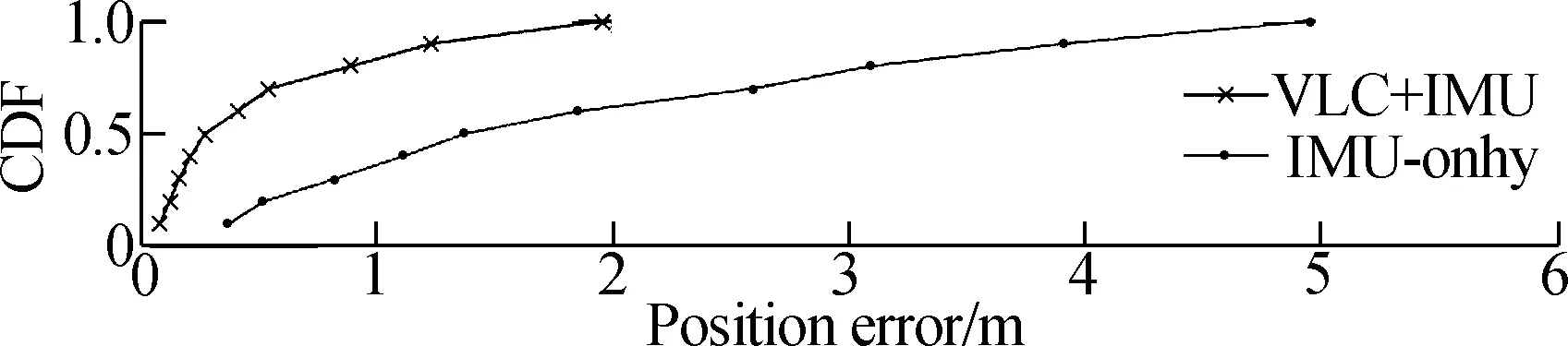
The curves in Fig.6 represent the cumulative distribution function (CDF) of position errors when the mobile

Fig.6 Cumulative distribution function of position errors
target has moved approximately 50 m. The experimental results show that the CDF of VLC-only is similar to that of the proposed hybrid positioning algorithm, but the VLC-only algorithm can provide good results only when the mobile target moves under the illumination area. As time progresses, the maximum error of the IMU-only algorithm increases to about 5 m. The maximum error of the proposed hybrid positioning algorithm is less than 2 m, which is better than that from the integration of WiFi and the IMU algorithm with the maximum error of 4.86 m. The results of the proposed hybrid positioning algorithm show that it has calibrated the cumulative errors of IMU measurement and improves the positioning accuracy.
(a)
(b)
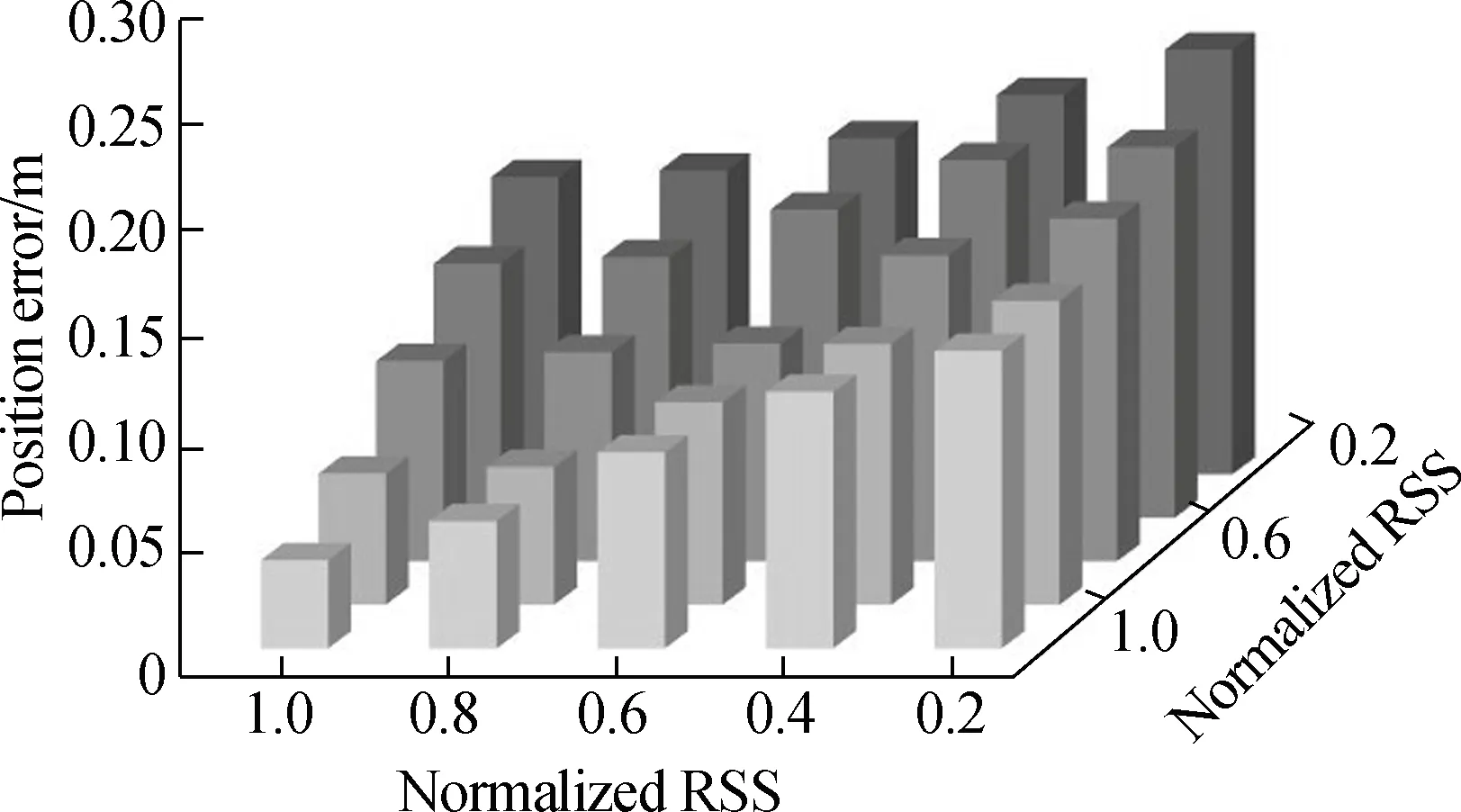
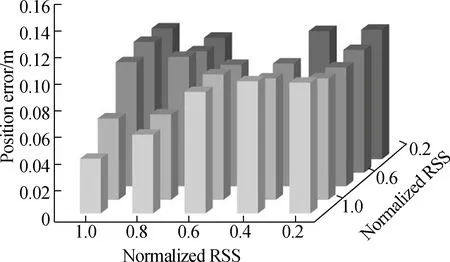
Fig.7Relationship between average position errors and normalized RSS.
(a) VLC-only; (b) VLC+IMU
Fig.7 shows the relationship between average position errors and normalized RSS. The average position errors from the proposed hybrid positioning algorithm and VLC-only algorithm are compared. When the mobile target moves with high normalized RSS, the position results from the proposed hybrid positioning algorithm are similar to those of the VLC-only algorithm. As the normalized RSS drops, the position errors of the VLC-only algorithm increase, but the position errors of the proposed hybrid positioning algorithm can be limited within 0.1 m. In Fig.8, the distributions of localization errors from the proposed hybrid positioning algorithm and IMU-only algorithm are investigated when the mobile target moves 1 lap and 10 laps. The figure shows that 90% of position errors of the proposed hybrid positioning algorithm are no more than 0.2 m. Only if the mobile target is away from the illumination range for a long time,

(a)

(b)

(c)
(d)
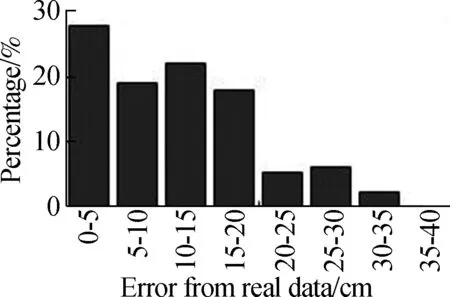
Fig.8Position errors range distribution of 1 lap and 10 laps.
(a) The IMU position error of 1 lap; (b) The IMU position error of 10 lap; (c) The AKF-WLS position error of 1 lap; (d) The AKF-WLS position error of 10 laps
(a)
(b)
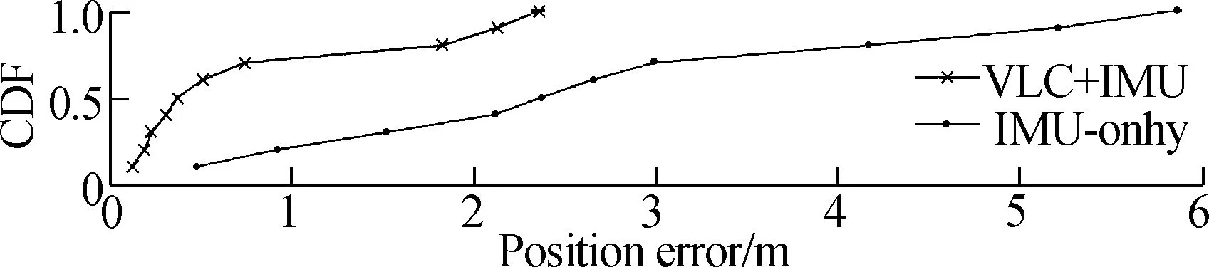
Fig.9Position errors cumulative distribution function with different velocities.
(a) With velocity of 0.4 m/s; (b) With velocity of 0.8 m/s
will the errors increase larger than 0.25 m. The average error of the proposed algorithm is 86% that of the IMU-only algorithm average error. Due to the cumulative errors, when the mobile target moves 10 laps, the average error of the IMU-only algorithm increases to be around two times that of the average error of 1 lap. At the same time, the proposed hybrid positioning algorithm can limit an average error under 0.15 m after 10 laps, which is 60% that of the IMU-only algorithm. The CDF in Fig.9 shows that the increase of velocity will affect the performance of positioning. When the mobile target has moved approximately 50 m, the maximum error of the proposed algorithm is about 3 m lower than that of the IMU-only algorithm with the velocity of 0.4 m/s and the gap is up to about 3.5 m with the velocity of 0.8 m/s. As shown in the figure, the comparison between the proposed hybrid positioning algorithm and IMU-only algorithm illustrates that the proposed algorithm provides a much more precise positioning accuracy than the IMU-only with higher velocity. Therefore, the IPS based on the proposed hybrid positioning algorithm can not only extend the VLC localization range, but also calibrate the positioning of the IMU.
5 Conclusion
An indoor positioning system is designed by applying a hybrid positioning algorithm which fuses the VLC RSS and IMU data for mobile target tracking. The alignment before localization can reduce the measurement errors of IMU and VLC RSS. Experimental results show that the developed IPS using the proposed hybrid positioning algorithm can extend the positioning range of VLC positioning, mitigate the drifts of IMU data and reduce the positioning error. The developed IPS using the proposed hybrid positioning algorithm has been demonstrated to be a very competitive method for indoor positioning, which can provide a promising approach for indoor positioning research.
杂志排行

Journal of Southeast University(English Edition)的其它文章
- Failure load prediction of adhesive joints under different stressstates over the service temperature range of automobiles
- A game-theory approach against Byzantine attack in cooperative spectrum sensing
- Dependent task assignment algorithm based on particle swarm optimization and simulated annealing in ad-hoc mobile cloud
- A cooperative spectrum sensing results transmission scheme with LT code based on energy efficiency priority
- Investigation of radiation influences on electrical parameters of 4H-SiC VDMOS
- A simplified simulation method of friction pendulum bearings