Recent development in automatic guidance and autonomousvehiclefor agriculture:A Review
2018-09-15HANShufengHEYongFANGHui
HAN Shufeng,HE Yong,FANG Hui
(1.College of Biosystems Engineering and Food Science,Zhejiang University,Hangzhou 310058,China;2.Key Laboratory of Spectroscopy Sensing,Ministry of Agriculture and Rural Affairs,Hangzhou 310058,China;3.John Deere Intelligent Solutions Group,Urbandale,IA50323,Iowa,USA)1
Abstract Automated agricultural vehicles can help alleviate labor intensity concerns,reducethecost of inputs,and improve the profitability.Significant progress has been made in automatic guidance for agricultural vehicles during the last two decades.More recently,research and development are focused on achieving more autonomy,with the ultimate goal to develop autonomous vehiclesor field robots for agricultural operations.This paper givesa review of recent development in autonomousvehicles,including localization,navigation control,mission planning,perception and safeguarding,and implement control.Trendsand futuredirectionsin autonomousvehicledevelopmentarediscussed.
Key words automatic guidance;autonomous vehicle;vehicle localization;vehicle navigation control;mission planning;vehicle safeguarding
Most farm operations, such as planting,cultivation,spraying,and harvesting,require the operator to drive the vehicle on evenly spaced paths to minimize overlaps and skips.It is an extremely demanding task because the operator,while driving,will also need to monitor and adjust the machine settings.There is a long history of creating automatic guidance systems in agriculture.JAHNS[1-2]reviewed hundreds of papers and patents related to early guidance systems.TILLETT[3]described a variety of techniques including mechanical and optical sensors for following existing features(rows),and a wide range of navigation methods including optical,electromagnetic,and radio techniques.However,none of those early systems and techniques were technically advanced and economically feasible to be applied to general agricultural field operations.
With the arrival of GPS(global positioning system)in the mid-1990s,it was apparent that most of the limitations of previous techniques were not present with GPS.The GPS-based guidance system has the advantages of high positioning accuracy and reliability in an open agricultural environment,low cost,and ease of operation and installation.Early research at Stanford University demonstrated that the carrier-phase GPS could be used to automatically guide a large-sized agricultural tractor(John Deere 7800)in parallel straight rows at a speed of 3.25 km/h with 2.5 cm tracking accuracy[4].From the late 1990s to early 2000s,researchers at the University of Illinois,in cooperation with Hokkaido University,had a strong research program for both automatic and autonomous guidance of agricultural vehicles[5-6].They developed a multiple sensor based agricultural vehicle navigation system,implemented it on a largesized tractor(Case-IH Magnum 8920),and achieved satisfactory tracking accuracy at high operation speed(>15 km/h).By early 2000s,several major agriculture equipment companies(e.g.John Deere,Case)started to commercialize the GPS-based guidance systems.Today,automatic guidance system based on GPS is a rapidly expanding technology in precision agriculture.It has become a standard feature in most large tractors and combines in the United States.
Significant research progress has been made in automatic guidance for agricultural vehicles during the last two decades.Both REID et al.[7]and LI et al.[8]provided good reviews of the research activities in automatic guidance technologies,including navigation sensor,vehicle motion model,navigation planner,and steering controller.This article discusses more recent developments in these areas.Additional technologiesare needed to achieve more autonomy beyond automatic guidance.Based on the conceptual design framework of an intelligent machine,the required technologies for autonomous vehicles can be categorized into four layers[9]as shown in Fig.1.Some of these technologies,such as machine coordination,perception and safeguarding,and implement control will be briefly reviewed.
1 Localization technology

Fig.1 Conceptual design framework for an autonomous agricultural vehicle[9]
Localization,also called positioning,is a process to estimate the location of the vehicle in a reference coordinate system.It is an essential technology in vehicle navigation.The global navigation satellite system(GNSS),coupled with the inertial sensor,is the most widely used localization system in agriculture.GNSS is an absolute positioning system.However,many agricultural applications require the machine to follow existing crop rows.In these cases,machine localization using relative positioning sensors has advantages. Localization through complementary sensors by sensor fusion can extend localization capability when one of the sensor signals is lost,and can improve localization accuracy when errorsexist from any singlesensor in thesystem.
1.1 GNSS for localization
The desired application accuracy in agriculture rangesfrom 12-40 cm for tillageto 2-4 cmfor planting.A standard GNSSreceiver is not capable of providing the positioning accuracy for any guidance applications in agriculture.Instead,differential correction techniques must be applied to improve the GNSS positioning accuracy.There are many different types of correction services.Free satellite differential services,such as the WASS in the United States,can typically provide an accuracy of 2-3 m so that they have very limited usage for agricultural vehicle guidance.Commercial satellite differential services,such as John Deere’s SF3 and OmniSTAR’s HP,can provide positioning accuracy within 10 cm worldwide.They are most commonly used positioning techniques for agricultural vehicle guidance.Real-time kinematic(RTK)correction can provide even higher accuracy(within 2 cm)with year-to-year consistency.It is a popular positioning system for precision agriculture including vehicle guidance.The basics of GPS and GPS-based automatic guidance systems were reviewed by HERAUD et al.[10].The main components of a typical GPS-based guidance system include GPSsensor,controller,electrohydraulic valve and manifold,steering anglesensor,and display.
During the last decade,the major focus of the GPSmodernization is the addition of new navigation signals (L2C,L5,and L1C) to the satellite constellation. This will enable faster signal acquisition,enhanced reliability,greater operating range,and better signal reception in challenging environments(e.g.under trees or even indoors).In parallel to the GPS modernization program in the USA,other GNSS systems are being developed around the world.The Europe’s Galileo system is expected to reach full operational capability by 2019.China’s Beidou system will also be globally available by 2020.With improved accuracy and enhanced reliability,GNSS will be the first choice of localization sensor for agricultural vehicle navigation.
1.2 Vision system for localization
When the vehicle needs to follow existing rows but the rows are not pre-mapped(taking the crop harvesting operation for example),GNSSalone cannot provide the localization needs for vehicle navigation.The localization sensor must be able to find relative position between the vehicle and the rows.Similar to human perception of rowswith hiseyes,avision system will be the best fit for this type of application.Both monocular vision and stereo vision can work.Localization with a monocular vision system involves the following steps:image acquisition,image calibration(conversion from image coordinates to vehicle/world coordinates), image segmentation (row feature extraction from the background),row detection(generation of a guidance directrix),and calculation of navigation errors(Fig.2).The key in the above steps is to find the row features from the acquired images.Many vision guidance algorithms have been studied for the agricultural outdoor environment.As for examples,REID et al.[11]developed a binary thresholding strategy using a Bayes classification technique for cotton crop at different growth stages.MARCHANT[12]reported a robust Hough transform method for finding crop rows in imagesof cauliflowers,sugar beet,and wheat with a typical lateral offset error of 18 mm.HAN et al.[13]applied a K-means clustering algorithm for image thresholding,developed a moment algorithm for row detection,and obtained a guidance directrix by using multipleregion-of-interest and a cost function.
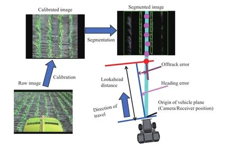
Fig.2 Localization with a monocular vision sensor for row-crop guidance
In recent years with the advances on computer technology,vehicle localization and guidance using stereo vision systems have become possible with affordable hardware.The main advantage of stereo vision in comparison with monocular vision remains in itscapability of rangedetection in addition to thecolor/feature detection.The range information can enhance row detection in the agricultural environment.The most challenging task in stereo vision processing is to determine the three dimensional(3D)depth information(3D point clouds)by stereo correspondence matching.A density grid can be generated from the 3D point clouds and used for navigation[14].Vehicle guidance with stereo vision hasbeen studied by several researchers[15-16].KISE et al.[17]reported a stereo vision-based crop row detection system to automatically navigate a tractor in a soybean field with a lateral deviation of lessthan 5 cm at the speeds up to 3.0 m/s.The vision system can provide very rich information,including color,shape,and depth of objects(rows),which can be easily integrated onto a vehicle due to the small footprint.The vision system is perhaps the best localization sensor for agricultural vehicle guidance when GNSSsignal is not available.
1.3 Sensor fusion for localization
Other localization sensors can also be used for vehicle guidance.A tactile sensor mounted in front of the vehicle and positioned between crop rows can detect the vehicle path deviation from the center of the crop rows.The vehicle is steered to the right when the left side of the tactile sensor touches the crop,and vice versa. Tactile sensors have been successfully implemented in commercial products as a lower cost alternative or backup to a GNSS-based guidance system[18-19].In addition,laser sensors,by detecting the range to the cut/uncut edge of the crop,can be applied for vehicle navigation during harvesting operations[20-21].Laser-based guidance systems are also commercially available for combine harvesters[22].
Eachtypeof sensorsdiscussed abovehaslimitations for vehicle navigation in agricultural environment.On the one hand,GNSS signals can be blocked near buildings and under trees.A GNSS-based guidance system cannot follow existing crop rows when rows are not pre-defined.On the other hand,a vision-based guidance system suffers from illumination variance and cluttered background in open agricultural fields.Tactile sensors and laser sensors can only work in limited operations(mainly harvesting)when the crop rows are clearly defined.In order to improve the localization accuracy and reliability,multiple sensors are often integrated in a navigation system by a sensor fusion.
A simple sensor fusion strategy is to select and use only one best sensor at a time from a multi-sensor system.The primary localization sensor might be switched from one to another due to change of the environment.For example,in a vision/GNSS combined row crop guidance system,when the crop rows can be detected by the vision,only vision output is used for localization.When the vehicle enters an area of significant crop washout or a headland,GNSS becomes the primary localization sensor.The transition from using one localization sensor to another should be smooth,otherwise the vehicle navigation control will become unstable.
Since each sensor in a multi-sensor system can provide localization information at the same time,many sensor fusion strategies will try to combine the outputs from each of the sensors.Kalman filter has become a standard approach to fuse the GNSSdata with inertial measurement unit(IMU)data to improve the reliability of position information.The fusion system can also achieve higher positioning update rate than GNSSalone.Modern GNSS receivers for agricultural vehicle guidance have an internal IMU fused by a tightlycoupled Kalman filter.
Fusion of GNSSand vision can provide one of the best localization solutions for agricultural vehicle navigation due to their complementary nature.However,the development of a proper fusion algorithm is challenging because the position measurements from these two sensors are in different coordinate systems.In addition,positioning noise covariance matrices are difficult to be quantitatively defined in a GNSS/vision system.ROVIRA-MÁS et al.[23]developed a Kalman filter to blend the data from both GPSand vision,and showed that the fusion system was able to reduce the effects of noisy GPStrajectories.HAN et al.[24]disclosed afuzzy logic approach to estimatethe weightsfrom both GPS quality data and vision quality data,and the position output is a linear weighted combination from both the GPS-estimated position and the visionestimated position.
2 Mission planning
Mission planning includes the optimization of vehicle or implement path based on criteria such as the shortest time to accomplish a given field operation.Mission planning will also optimize machine functions,typically the vehicle speed,associated with the vehicle path.Path planning is part of a mission planner that only optimizes the vehicle navigation path.Only the path planning will be discussed below.
2.1 Guidance patterns
The simplest path planning is to define a vehicle guidance pattern to match a desired farming operation.Some examples of the guidance patterns include:
Straight lines:A master straight line(usually referred to as an A-B line)is defined by entering two points or one point plus a heading.Subsequent parallel lines are automatically generated.The spacing between any adjacent two lines is fixed at a given amount called the swath width.This is the most common guidancepattern in agriculture.
Curves:A master curve line is defined by manually driving the vehicle along a curved path.Subsequently new curve lines are generated by offsetting the previous curve with a fixed swath width.The curve guidance pattern is useful when the field operation needs to follow field contour lines.The minimum turning radius of the vehicle needs to be considered in the generation of a subsequent new curve.There is no guarantee that two adjacent curves can be evenly spaced at every point,especially in sectionswith largecurvature.
Adaptive curves:A pattern similar to curves,but if the user takes manual control,the new curve path is recorded and acts as a master curve line for the next pass.
Pivots:A pattern consists of concentric circles separated by the swath width.The pivot guidance pattern is useful for farming operations with centerpivot irrigation.
Spirals:A pattern in which each swath grows concentrically by the swath width.This pattern does not need to be limited to circular spirals;in some cases,rectangular or arbitrary shapes are used.This guidance pattern is typically used for operations around field headlands.
The guidance patterns described above have been implemented in almost every commercial autoguidance product.The patterns are generated on-line without route/path optimization.The operator will need to manually drive the vehicle to the next path.
2.2 Optimized two dimensional(2D)path planning
Path planning optimizes an entire field operation route including both working paths inside the field and non-working paths such as end-of-row turns.The working paths should cover the entire field with minimum overlaps and skips (thus coverage planning)and the goal is to minimize the total operation time.Path planning is usually an off-line task.The planned paths can be applied to a vehicle with automatic guidance or to an autonomous vehicle.An autonomous vehicle will automatically execute the entire planned paths,whereas the automatically guided vehicle will need a human operator to steer on the non-working paths(turns).A 2D path planner creates optimized paths on a 2D planar surface.
An optimized path planner will first decompose an entire field into several sub-regionsand find a best path direction for each sub-region.Field decomposition can improve the efficiency of field operations especially when the field boundary is irregular shape.CHOSETet al.[25]explored trapezoidal decomposition for coverage path planning.However,it was not clear how the direction of the trapezoidal decomposition lines was determined.Field decomposition,including the selection of the path direction,is still more of an art than a science.Following the longest edge of the field is a simplebut practical strategy for most fields.
Once the best path direction is determined,the optimized path planner divides the field into partitions.A partition is an area where paths can be constructed by simply traveling back and forth along adjacent rows.No optimization is needed within a partition.After this simplification,the path planning becomes more manageable;it is simple to find the optimized connecting paths among all the partitions.This is clearly a traveling salesperson problem(TSP)which can besolved by many algorithms.
JIN et al.[26]applied a geometric model and developed an algorithm that could optimally decompose a planar field.Their optimization process is based on a headland turning cost function and a divide-and-conquer strategy.To reduce the total turning cost,the number of turnsisminimized and turnswith high costsareavoided.Their path planner was applied to planar fields with complexity ranging from simple convex shapes to irregular polygons with multiple obstacles.Their algorithm showed good potential to improve field operation efficiency on planar fields.Fig.3 shows an exampleoutput from their 2Dpath planner,whereafield was decomposed into two subfields and the optimal travel direction for each subfield was determined.

Fig.3 Example of 2D path planner output with two decomposed subfields and optimal travel direction[26]
By using an optimized path planner,the total non-working travel distance can be reduced by up to 50%compared with the conventional non-optimized method[27].However,there are many other factors,such as the in-field supply logistics,that need to be considered before farmers can use the mathematically optimized routegenerated by apath planner[28].
2.3 Optimized 3D path planning
A 3D path planner createsoptimized pathson a 3D terrain.Literature on 3D path planning in agriculture is limited.JIN et al.[29]approached the problem by firstly developing an analytical 3D terrain model with B-spline surface fits to facilitate the computation of various path costs.They then calculated coverage costs,which included a soil erosion cost and a curved path cost,for each particular coverage path solution.They developed a terrain decomposition and classification algorithm to divide a field into sub-regions with similar field attributes and comparatively smooth boundaries.The most appropriate path direction of each region minimized the coveragecosts.
3 Navigation control
Building on the foundation of localization and mission planning,the purpose of navigation control is to automatically steer the vehicle along the desired path and minimize the tracking errors.Development of the navigation control requires two steps.The first step is to calculate the tracking errors,typically a cross-track error and a heading error.The update rate in tracking error calculation is based on the rate of position update,typically 5-10 Hz for a GNSS-based system.The second step is to compute steering corrections that must be applied to the steering actuator(an electrohydraulic valve or an electrical motor)to minimize the tracking errors.This step is implemented in a microcontroller with steering controller software.It is called lower level control with amuch higher update rate(typically 50 Hz).
In calculating the tracking errors,a lookahead point from the desired path is selected.The location of the lookahead point can impact the tracking performance,especially for curve-row guidance.The lookahead distance is often dependent on the vehicle speed[30].
There have been abundant literatures on steering controller development for agricultural vehicle navigation since 1970s.Most controller designs start with vehicle modeling.Since agricultural vehicles operate at lower speeds(e.g.lessthan 4.5 m/s),vehicle dynamic effects such as side slips can be ignored,and a kinematic vehicle model will be sufficient to describe thevehicle motion.For front-wheel steered vehicles,the classic“bicycle model”of the automobile,which treats the pair of tires at each end of the vehicle as a single tire,is typically used to develop various closed-loop feedback controllers.The closed-loop control technique is necessary for agricultural vehicle navigation because of the uncertain operation environment with many disturbances.The proportional-integral-derivative(PID)based controllers are the most common,primarily because they are less sensitive to disturbances to the system so they can be applied to various field operations.Different variations of PID-based controllers have been developed.One example is the gainscheduled PID controller where some or all of the PID gainscan beadjusted based on thevehicle speed.Selftuning PID control is a promising technique for agricultural guidance control.
Many other steering control algorithms have been studied as well.For examples,O’CONNOR et al.[4]developed a linear-quadratic regulator(LQR)based controller to guide a large-sized agricultural tractor.QIU et al.[31]developed a fuzzy steering controller by using the steering rate command and the steering angle error as the inputs to determine a proper steering control signal.TU[32]developed a sliding mode control based navigation controller for a 4WS/4WD system.These controllers showed some success,but they have not been implemented in commercial guidance products.Steering controllers for high-speed operations(e.g.spraying at 9.0 m/s)is still a research topic.
4 Autonomousvehicles
Localization,mission planning and navigation control enable vehicle automatic steering,which constitute the basic technologies in autonomous vehicle or field robot.Recent progresses in the machine automation spectrum as related to full vehicle autonomy are briefly discussed below.
4.1 Implement control
There is a wide range of agricultural implements such as cultivators and planters that are attached to the tractors.Automatic control of these implements is essential for automated or autonomous operations.Implement control includes implement path control and implement function control.Implement path control is often called implement guidance.Examples of implement function control include depth control of tillagemachinesand rate control of planters.
The goal of implement guidance is to keep the implement on the desired path.Due to the implement drift caused by varying soil conditionsaswell asgravity in sidehill applications,the implement path will be different from the tractor path.There are two types of implement guidance systems.The first type is active implement guidance system, whose system automatically steers the implement to the guidance line by providing a correction to the implement steering mechanism.Active implement guidance system requires a localization sensor for the implement(e.g.GPS or vision)and a steerable implement,and it isnot practical for small implements.The second type of implement guidance system is passive implement guidance.Passive implement guidance does not require a steering mechanism on the implement,and the drift of the implement path iscorrected by adjusting thetractor path.Passive implement guidance requires a good model of the tractor-implement system,and may or may not need the localization sensor on the implement.Both active and passive implement guidance systems are now commercially available[33].
4.2 Machine coordination
Machine coordination is a type of field operations in which multiple machines work together to achieve a field operational goal.Combine harvesting operation with a grain cart is a good example.The tractor pulling the grain cart needs to be positioned alongside the moving harvester in order for the harvester to unload the grain on the go.Both speed and position of the tractor are automatically controlled based on theharvester’sspeed and position.Another example of machine coordination in agriculture is the leader-follower operation.A group of tractors work in the same field with a certain formation with one tractor as the leader and the rest as the followers.The formation might change based on the location of the leading tractor.ZHANG et al.[34]reported a machine coordination system with two robotic tractors to improve the work efficiency by at least 80%.
In addition to the automatic guidance control,key technologies in machine coordination are mission planning and wireless communication.The multivehicle mission planner needs to develop an operation path for each individual vehicle in the fleet such that the total cost can be minimized and the paths are collision free.Research on multi-vehicle mission planning in agriculture is much needed.Wireless communication technology for multivehicle coordination within a field is mature and reliable.As an example,the Machine Sync product from JOHN DEERE[35]creates an in-field wireless network that can include 10 machines(combines and tractorswith grain carts)working together.
4.3 Perception and safeguarding
An autonomous vehicle must perceiv e its environment to carry out its tasks.The primary goal of machine perception is to ensure safe operation of the vehicle(safeguarding).Obstacle detection,recognition,and avoidance are typical examples in vehicle safeguarding.
There are many different types of perception sensors.Most of them operate in the electromagnetic spectrum,including monocular vision,stereo vision,laser,radar,ultrasonic sensor,and more recently active 3D range camera.All of these sensors have been studied for vehicle safeguarding in agricultural environments[36-37].Because agricultural operations are exposed to a very challenging environment(e.g.dust,rain,and extreme lighting condition)for perception sensors,no single type of sensor has been shown to work reliably in all operating conditions and to have clear advantages or disadvantages over the others.Selection of a perception sensor should consider range,robustness to lighting condition,robustness to dust,spatial resolution,maintenance,and cost.Table1 summarizes the ratings for each of major types of perception sensors[9].
Machine vision is perhaps the most promisingtechnology for agricultural perception applications because it can provide a vast amount of data at a relatively low cost.In addition,development of sensor fusion systems for safeguarding will continue to be a major effort.Appropriate sensor fusion algorithmsare much needed in thisarea.
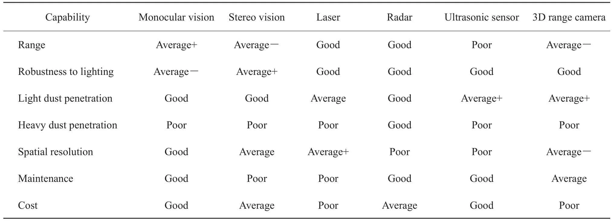
Table1 Perception sensor ratings[9]
5 Future directions
The past two decades have witnessed an extraordinary progress in automated vehicle guidance.GPS-based auto-guidance systems are now widely adopted by farmers.The next step in the vehicle automation spectrum is the development of fully automated vehicles,or autonomousvehicles.
Some of the notable achivements in the development of autonomous agricultural vehicles included the vision-based system for a New Holland 2550 speedrower by Carnegie-Mellon University Robotics Institute[38]and the sensor-fusion based system for a Case-IH Magnum 8920 tractor by University of Illinois[6].Although their systems could perform autonomous operations,they both lacked the perception and safeguarding capability.During the last 10 years,Ag equipment companies have showed great interests in developing and commercializing autonomous vehicles.As for examples,KINZE[39]has developed a driverless grain cart tractor to automate the harvesting operation since 2011;CNH[40]revealed an autonomous concept vehicle.However,it will be a long journey before these prototypescan becommercialized dueto lack of reliable safeguarding.Fig.4 includes some of the best examples and prototypes of highly-automated and autonomous vehicles developed during the last two decades.

Fig.4 Examples and prototypes of highly-automated and autonomous vehicles developed during the last two decades
Significant hurdles exist in developing autonomous vehicles.The most challenging technical hurdle is vehicle perception and safeguarding.Safeguarding sensors are still very expensive and not robust enough to work under all agricultural environments.In recent years,the rapid development of driverless car technology in the automotive industry has made cost-effective safeguarding sensors promising.With breakthroughs in vehicle perception and safeguarding technology,highly automated agricultural vehicles or even fully autonomous vehicleswill become areality in thenear future.