Simulation and experimental investigation on a dynamic lateral flow mode in trepanning electrochemical machining
2017-11-20DongZHUZhouzhiGUTingyuXUEAoLIU
Dong ZHU,Zhouzhi GU,Tingyu XUE,Ao LIU
College of Mechanical and Electrical Engineering,Nanjing University of Aeronautics and Astronautics,Nanjing 210016,China
Simulation and experimental investigation on a dynamic lateral flow mode in trepanning electrochemical machining
Dong ZHU*,Zhouzhi GU,Tingyu XUE,Ao LIU
College of Mechanical and Electrical Engineering,Nanjing University of Aeronautics and Astronautics,Nanjing 210016,China
An appropriate flow mode of electrolyte has a positive effect on process efficiency,surface roughness,and machining accuracy in the electrochemical machining(ECM)process.In this study,a new dynamic lateral flow mode,in which the electrolyte flows from the leading edge to the trailing edge,was proposed in trepanning ECM of a diffuser.Then a numerical model of the channel was set up and simulated by using computational fluid dynamics software.The result showed that the distribution of the flow field was comparatively uniform in the inter-electrode gap.Furthermore,a fixture was designed to realize this new flow mode and then corresponding experiments were carried out.The experimental results illustrated that the feeding rate of the cathode reached 2 mm/min,the best taper angle was about 0.4°,and the best surface roughness was up toRa=0.115 μm.It reflects that this flow mode is suitable and effective,and can also be applied to machining other complex structures in trepanning ECM.
©2017 Chinese Society of Aeronautics and Astronautics.Production and hosting by Elsevier Ltd.This is an open access article under the CC BY-NC-NDlicense(http://creativecommons.org/licenses/by-nc-nd/4.0/).
1.Introduction
The diffuser is one of the key components in an aero engine.1It is generally made of hard-to-cut materials and the thickness of its blade is thin,so its manufacture is difficult by a traditional machining process.Electrochemical machining(ECM)is an efficient and economic technology because of its advantages such as regardless of material characteristics,no cutting force and no tool wear.2–7In the ECM of diffusers,an appropriate flow mode of electrolyte has a positive effect on processing efficiency,surface roughness,and machining accuracy.
A lot of research has been conducted on the ECM process of diffusers or other complex components.Some innovative flow modes have been presented to enhance the uniformity of a flow field.Zhu et al.8,9proposed a W-shape flow mode and improved the process stability and surface quality in ECM of a blade.Zhu et al.10also designed a dynamic additional flow mode and enhanced the machining efficiency.Tang et al.11,12presented a reversed flow pattern in ECM of a closed integer impeller and improved the surface roughness of samples.Xu et al.13proposed a Π-shaped flow pattern to machine the cascade passages of a blisk and enhanced the feeding rate of the cathode and the surface roughness.In addition,plenty of computational methods have been adopted to analyze the characteristics of parameters in the inter-electrode gap and acknowledge the anodic shaping rules.Sawicki and Paczkowski14investigated the effects of the hydrodynamic conditions of electrolyte flow on critical states using an example of machining curved surfaces with any sort of outlines and curved rotating surfaces in ECM. Dabrowski and Paczkowski15presented a mathematical model of twodimensional electrolyte flow and analyzed the distributions of parameters such as electrolyte velocity,pressure and thickness of the inter-electrode gap.Rousar and Riedel16measured the critical current density under different Reynolds numbers in flow-through cells.Fujisawa et al.17built a multiphysics model,including multiphase flow,thermal fields,and electric fields,to forecast the final shape of a three-dimensional compressor blade.Klocke et al.18–20established an interdisciplinary model,considering electric field,fluid flow,and heat transfer,to simulate the ECM process for aero engine blades.
This paper mainly aims to investigate the distribution of the flow field in trepanning ECM.Furthermore,an innovative flow mode,namely dynamic lateral flow mode,is proposed to improve the flow situation of electrolyte in the channel.Then a simulation is conducted to analyze the characteristics of the flow field,and corresponding experiments are carried out to verify the effectiveness of this new mode.
2.Description of a new flow mode in trepanning ECM
A schematic diagram of the trepanning ECM method is shown in Fig.1.In the process,a tool electrode with a cavity is used as the cathode,and it continuously feeds towards a workpiece along the feeding direction at a constant feeding rate.When a power supply is applied on the two electrodes and an electrolyte is provided,the workpiece will begin to dissolve and the electrolytic products will be flushed away simultaneously.Then,a part will be formed gradually with the cathode feeding.This method is suitable to fabricate a part with the same cross section.
In trepanning ECM,the forward flow mode is generally used(Fig.1(a)).Specifically,the electrolyte is firstly pumped into the cavity of the electrode,flows through the channel along the blade,then gets into the inter-electrode gap between the cathode and the workpiece,and at last comes out of the channel freely to the electrolyte tank.In this traditional mode,the channel becomes large greatly when the electrolyte flows out of the outlet.It means that the flow field is open,which may lead to the instability of the process because streamlines at the outlet are divergent.The description of this shortcoming is shown in Fig.1(b).As shown in the figure,streamlines at the channels of the blade body are good,whereas they are not even at the trailing and leading edges because of a dramatically transition of the profile.Therefore,the distribution of the flow field is not uniform in the entire inter-electrode gap.
To overcome the defect in the forward flow mode,a dynamic lateral flow mode is proposed in trepanning ECM(Fig.2).In this new mode,the inlet is next to the leading edge and the electrolyte is provided from the leading edge to the trailing edge.Meanwhile,the inlet is moving in the process and is followed with the cathode feeding.Compared with the static flow mode in which the inlet is not moving,this movement enables the electrolyte to flow into the inter-electrode gap straightly through the whole process without any turning when the electrolyte flushes into the machining area.It will make the process stay in a more stable stage.
In addition,there are some advantages of this new mode compared with the forward flow mode.(1)The electrolyte is sealed in a fixture and flows along the designed channel.The flow field can be controlled and is not open at the outlet,so its uniformity will be more even and the process will be more stable.(2)The flow conditions at the area of the machined surface are not good,which will decrease the scatter dissolution on the machined profile indirectly.Then the surface roughness will be reduced on the blade.
3.Simulation of trepanning ECM
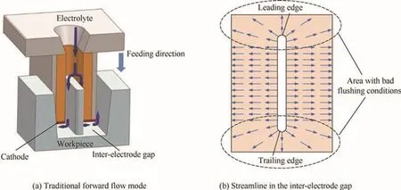
Fig.1 Schematic diagram of trepanning ECM by using forward flow mode and distribution of streamlines in inter-electrode gap.
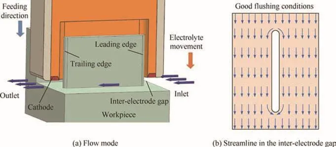
Fig.2 Description of dynamic lateral flow mode and distribution of streamlines in inter-electrode gap.
In order to observe availability of the new flow mode,the fluid situation of the electrolyte in the channel is simulated in this section.To simplify the simulation process,two assumptions of the fluid motion are made first.(1)Wherever the fluid is in contact with a solid boundary,there is no motion or slip relative to that boundary of the fluid particles adjacent to it.(2)The shearing stress between adjacent layers offluid of an infinitesimally small thickness is taken to be proportional to the rate of shear in the direction perpendicular to the motion.Then the procedures of the simulation,including modeling,loading,and solving,are introduced in trepanning ECM as follows.
3.1.Modeling
The first procedure of the simulation is modeling.There are two types of machining gap in trepanning ECM,namely equilibrium gap⊿band side gap⊿s(Fig.3(a)).Their equations are expressed as follows according to the ECM theory:
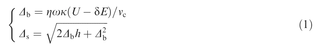
where η is the current efficiency,ω is the electrochemical equivalent,κ is the electrolyte conductivity,Uis the power supply voltage,δEis the decomposition voltage,vcis the feeding rate of the cathode,andhis the feeding distance from the starting pointAto a certain pointBon the workpiece profile.
Then the front gap,between the hub of the workpiece and the cathode,and the side gap,between the outsides of the cathode and the workpiece,can be obtained according to Eq.(1).In addition,because there is an insulator inside the cathode,the scatter dissolution is neglected and then the side gap between the machined body and the cathode equals to⊿bapproximately based on the shaping rules in ECM.Combined with actual machining conditions in trepanning ECM,a model of the flow field is built at the final stage of the process after calculation(Fig.3(b)).In the figure,PIis the pressure at the electrode inlet andPOis the back pressure at the electrode outlet.PlanesSandQare selected to observe the flowing situation below.The position of PlaneSis in the middle of the interelectrode gap,whereas PlaneQis perpendicular to PlaneSand through the midpoint of the flow path.
3.2.Loading
The second procedure of the simulation is loading on the boundary,and the conditions of the boundary are determined by setting pressures on the inlet and the outlet in this study.To obtain the initial values of pressures,the critical velocity of the electrolyte should be discussed first.According to the ECM theory,there are two criteria of velocityuto ensure a process stay in a stable state:(1)to ensure the fluid in a turbulent state in the machining gap(uT)and(2)to control the temperature rise(u0).The equations of these two criteria are described as follows:
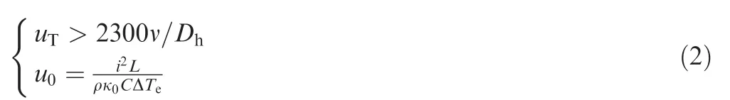
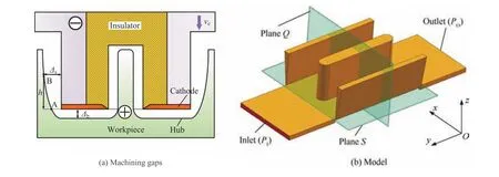
Fig.3 Description of machining gaps and a three-dimensional model of new flow mode.
where ν is the kinematic viscosity,Dhis the hydraulic diameter,iis the current density,Lis the flow length,ρ is the electrolyte density,κ0is the electrolyte conductivity at the inlet,Cis the heat capacity of the electrolyte,and ΔTeis the allowed temperature rise.
To realize the two criteria,the electrolyte velocity should be higher thanuTandu0.Then these two values can be calculated by combining with actual experimental conditions.The results of the calculation are thatuT=15.2 m/s andu0=3.12 m/s.The critical velocity should be about higher than 15.2 m/s.Accordingly,the pressure at the inlet should be high enough to ensure the electrolyte to reach the critical velocity.The expression of the critical pressure is defined as follows:
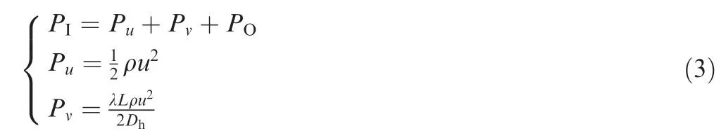
wherePuis the dynamic pressure,andPνis the viscous friction pressure(when the flow is turbulent λ=0.3164/Re0.25).
Then the critical pressurePIis obtained to meet the requirements of the critical velocity,and its value is about 0.46 MPa after calculation(herePO=0 MPa).Therefore,the pressure at the inlet should be higher than this critical value.Furthermore,the higher the pressure is,the higher the velocity of the electrolyte will be.Then,it will make the removal of the dissolving products quicker and enable the process more stable in a certain degree.On the other hand,there is a limitation of the capacity of pump in the experimental system,so the pressure cannot be too high.Taking into account these aspects,the initial pressure at the inlet is determined,and it equals to 1.2 MPa in this study.This value is much higher than the critical pressure to meet the two criteria of velocity and obtain a high velocity of the electrolyte in the inter-electrode gap;meanwhile,it can also sustain the normal work of the pump.Consequently,the conditions of the boundary are determined,that is,PI=1.2 MPa andPO=0 MPa.
3.3.Solution and discussion

Fig.4 Distribution of electrolyte velocity on Plane S and Q in the channel.
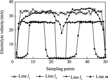
Fig.5 Curves of velocities on lines sampled from Planes S and Q.
After loading the conditions on the boundary,the simulation process is solved by using the computational fluid dynamics software(ANSYS Workbench),and the distribution of the flow field in the channel is achieved.Specifically,PlanesSandQare chosen to re flect the flow field,and the distributions of velocity on PlanesSandQare shown in Fig.4.As shown in the figure,(1)the velocity is uniform on the whole on PlaneS,and its values are high in most of the area(Fig.4(a)).Specifically,the velocities at the inlet and on the two sides between the blade and the cathode at the outlet are relatively higher than that in the center of the gap,which may make the exhaust of electrical products quicker and lead to higher surface quality at these two areas.(2)However,there is an area with a bit lower velocity at the outlet of the machining gap compared with those in other areas on PlaneS,just behind the trailing edge.This phenomenon occurs because of the block of the blade.The low-velocity area might lead to a low dissolution rate of the workpiece and even cause flow marks on the workpiece.(3)The velocities of the electrolyte on PlaneQthat is in the area between the blade and the cathode are comparatively lower than that in the inter-electrode gap(Fig.4(b)),which is good to decrease the dissolution of the workpiece and increase the surface quality.
Furthermore,three lines on PlaneSand one line on PlaneQare used to analyze the velocity in the channel quantitatively.Specifically,Linesl1,l2,andl3,which are perpendicular to the flow path,are selected on PlaneS,while Linemon PlaneQis chosen along the direction of the dotted line whose position is in the middle of the channel from the starting point to the ending point.Then 50 points are sampled on each line evenly and their values are obtained from the starting point.The curves of velocities on all lines are illustrated in Fig.5.The following results are obtained according to the figure.(1)The velocities onl1are higher than those on other lines as a whole and the highest value can reach 34.89 m/s.(2)The distribution of velocities onl3is not very uniform.The values are higher on two sides than that in the middle.However,this smallest value in the middle is about 17.65 m/s which exceeds the critical velocity,so it can ensure the stability of the process.(3)In addition,all velocities onl2are close to each other and their values are about 25 m/s.Nevertheless,the values are near 0 in the non-machining area which can be observed from the distribution of velocities on Linem,which can be good for the surface quality.In a word,the flow field is good in the channel and this flow mode is suitable for trepanning ECM.Then experiments will be conducted to verify the effectiveness of the simulation.
4.Experimental results and discussion
4.1.Experimental procedures
A self-developed ECM system was built to verify the simulation process.The machining conditions were displayed in Table 1.The pressure was adopted according to the simulation boundary.
A new fixture was designed and fabricated to realize the lateral flow mode.Then experiments were carried out,and the process site is shown in Fig.6.During the process,the electrolyte inlet was feeding with a movement of the cathode to ensure the inlet provide the electrolyte into the interelectrode gap invariably.After machining,the surface roughness of samples were measured by a roughness tester(its model is MAHR PS1)and the machining accuracy was measured using a three-coordinate measuring machine(its model is TESA Micro-Hite 3D).
4.2.Effects of lateral flow mode on machining efficiency
Under the above conditions,a series of experiments about the limitation of machining efficiency were conducted by using this lateral flow mode in trepanning ECM,and the machining process was stable when the feeding rate of the cathode was increased from 0.5 to 2 mm/min.Moreover,the current changes were illustrated under different feeding rates during the whole process in Fig.7.As shown in the figure,the current changed greatly with an increase of the feeding rate,and the maximum values are about 280,499,700,and 905 A under the four situations,respectively.In addition,when the feeding distance was about less than 1.5 mm,the currentenhanced observably,whereas it increased slowly when the feeding distance exceeded 1.5 mm and the process got stable comparatively.However,the machining process became unstable and the current varied violently as the feeding rate reached 2.5 mm/min.The reason may be that with an increase of the feeding rate,the interelectrode gap became smaller and smaller.The smaller gap speeded up the material removal rate while it also made the electrochemical products exhaust out difficultly.Therefore,the limitation of the feeding rate is 2 mm/min under the above experimental conditions.The machining efficiency was improved obviously by using this flow mode.The result reflected that the distribution of the flow field might be uniform in the inter-electrode gap because the feeding rate reached 2 mm/min.The improvement of the machining efficiency revealed that this flow mode is effective and suitable for trepanning ECM.
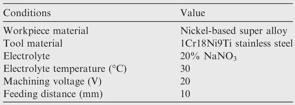
Table 1 Experimental conditions for trepanning ECM.
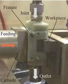
Fig.6 Machining equipment on site.
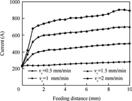
Fig.7 Current changes during the ECM process with different feeding rates of the cathode.
4.3.Effects of lateral flow mode on surface quality
The surface quality was analyzed on the body and hub of machined samples under different feeding rates by using the lateral flow mode(Fig.8).As shown in the figure,(1)the surface of the hub was smooth in most of the area,which was better than that of the body,because the latter was machined by the scatter dissolution which would lead to bad surface quality.Meanwhile,the velocity of the electrolyte in the machining gap was higher than that in the side gap,which would also make the surface quality better on the hub.(2)The labeled areas in the dotted line is brighter than other areas on the hub,which means that the surface quality is better than that in other places.Compared with the simulation results in Fig.4,these areas are just the places where the electrolyte velocity is high.The higher the velocity is,the faster the dissolution products are carried away,which will lead to better surface quality of machined samples.(3)There is a small flow mark at the outlet,just behind the blade.With the cover of the blade,the velocity of the electrolyte is low(Fig.4(a))which makes the exhaust of electrical products difficult and lead to bad surface quality.Therefore,the experimental results are consistent with those of the simulation.In addition,experiments of the forward flow mode were also performed,and the situation of surface quality on the hub is illustrated in Fig.8(b).There were obvious flow marks at the top and bottom of the hub.This phenomenon occurred because of the bad flushing conditions of the electrolyte in the areas of the leading and trailing edges.Furthermore,the surface roughness was worse on the blade body compared with that in the lateral flow mode.Therefore,the lateral flow mode was more suitable than the forward flow mode for trepanning ECM according to the surface quality of machined samples.
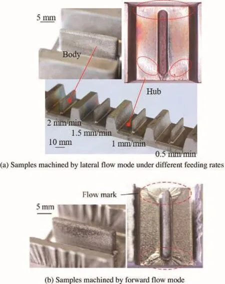
Fig.8 Surface quality on different parts of samples under lateral and forward flow modes.
Moreover,the surface roughness Ra on the hub and blade body of samples machined under the lateral flow mode was measured to analyze the surface quality quantitatively.The surface qualities of samples under different feeding rates are shown in Fig.9.The following conclusions could be obtained according to the figure.(1)The surface roughness Ra on the hub was better than that on the blade body.The reason might be that the current density on the hub was higher than that on the blade body which made the materials dissolved more evenly.(2)With an increase of the feeding rate of the cathode,the surface roughness enhanced obviously on the hub and the best value was aboutRa=0.115 μm,whereas it improved gradually on the body and the best value was approximatelyRa=1.585 μm.This phenomenon happened because of the following reasons:the current density was high at the hub;the influence was more significant than that at the blade body;the roughness situation was consistent with simulation results;the flow condition was not good and the electrolyte velocity at this place was lower,resulting in improper flushing conditions and leading to poor surface roughness.
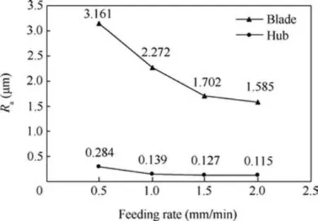
Fig.9 Surface roughness of the machined samples under different feeding rates.
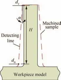
Fig.10 Schematic graph of taper in trepanning ECM.
4.4.Effects of lateral flow mode on machining accuracy
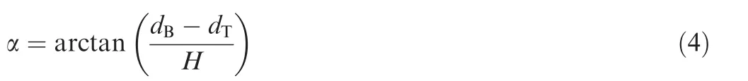
In trepanning ECM,the deviations were different between the top and bottom of a sample.Generally,the deviation at the bottom was larger than that at the top on the whole because of scattered corrosion.Although the inside walls of the cathode were insulated,there might still be weak effects of scattered corrosion on the machined surface.In other words,there was a taper angle of the machined sample,which was chosen to analyze the machining accuracy under the lateral flow mode in this study.The schematic graph of this phenomenon is described in Fig.10.
To obtain the taper angle,a line on the samples was measured by a three-coordinate measuring machine.Its direction was from the top to bottom of the sample,and the schematic graph of this line is described in Fig.10.The taper angle is defined as follows:wheredTis the deviation between the sample and the model at the top of the detecting line,dBis the deviation between the sample and the model at the bottom of the detecting line,andHis the length of the detecting line.
Then the profiles of the detecting line on samples machined under different feeding rates were measured.The taper angles were calculated according to Eq.(4)after measuring,and the results are illustrated in Fig.11.The taper angles were 1.81°,1.25°,0.73°,and 0.4°on the line as the feeding rates were 0.5,1,1.5,and 2 mm/min,respectively.It shows that the taper angle became smaller with the feeding rate increasing.The reason might be that the influence of scattered corrosion got weaker because of less action time of dissolution.Then the change of the deviation between the top and bottom became smaller with an increase of the feeding rate of the cathode.
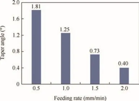
Fig.11 Taper angle of samples machined under different feeding rates.
5.Conclusions
(1)A dynamic lateral flow mode,in which the electrolyte flows from the leading edge to the trailing edge,was proposed to improve the uniformity of the flow field in the inter-electrode gap in trepanning ECM.
(2)A numerical model of the inter-electrode gap was set up and simulated by using the computational fluid dynamics software ANSYS Workbench.The results showed that the velocities of the electrolyte in the interelectrode gap were higher than the critical velocity which could ensure the stability of the process.It reflected that this new flow mode was suitable for trepanning ECM.
(3)A new fixture was designed to realize this new flow mode and then corresponding experiments were carried out.The experimental results illustrated that the feeding rate of the cathode reached 2 mm/min,the best taper angle was about 0.4°,and the best surface roughness was up toRa=0.115 μm.The results indicated that this flow mode was suitable and effective.For further research,parameters such as electrolyte pressure and voltage will be optimized to enhance accuracy and efficiency.
Acknowledgements
This study was co-supported by the National Natural Science Foundation of China(51675271)–China,Key Project of Jiangsu Provincial Research and Development(BE2015160)–China,Fundamental Research Funds for the Central Universities(NE 2017003)–China.
1.Gottlich E.Research on the aerodynamics of intermediate turbine diffusers.Prog Aerosp Sci2011;47(4):249–79.
2.Klocke F,Zeis M,Klink A,Veselovac D.Technological and economical comparison of roughing strategies via milling,EDM and ECM for titanium-and nickel-based blisks.Proc CIRP2012;2:98–101.
3.Rajurkar KP,Zhu D,McGeough JA,Kozak J,De Silva A.New developments in electrochemical machining.Ann CIRP1999;48(2):567–79.
4.Kozak J.The computer simulation of electrochemical shaping processes.IAENG Trans Eng Technol,Lect Notes Electr Eng2013;170:95–107.
5.Chang CS,Hourng LW.Two-dimensional two-phase numerical model for tool design in electrochemical machining.J Appl Electrochem2001;31(2):145–54.
6.Xu ZY,Xu Q,Zhu D,Gong T.A high efficiency electrochemical machining method of blisk channels.CIRP Ann-Manuf Technol2013;62(1):187–90.
7.Zhu D,Zhu Di,Xu ZY,Zhou LS.Trajectory control strategy of cathodes in blisk electrochemical machining.Chin J Aeronaut2013;26(4):1064–70.
8.Zhu D,Zhu Di,Xu ZY,Xu Q,Liu J.Investigation on the flow field of W-shape electrolyte flow mode in electrochemical machining.J Appl Electrochem2010;40(3):525–32.
9.Zhu D,Zhu Di,Xu ZY.Optimal design of the sheet cathode using W-shaped electrolyte flow mode in ECM.Int J Adv Manuf Technol2012;62(1–4):147–56.
10.Zhu D,Zhang JC,Zhang KL,Liu J,Chen Z,Qu NS.Electrochemical machining on blisk cascade passage with dynamic additional electrolyte flow.Int J Adv Manuf Technol2015;80(1–4):637–45.
11.Tang L,Yang F,Zhu QL,Gan WM.Electrochemical machining flow field simulation and experimental verification for irregular vortex paths of a closed integer impeller.Int J Adv Manuf Technol2016;83(1–4):275–83.
12.Tang L,Gan WM.Utilization of flow field simulations for cathode design in electrochemical machining of aerospace engine blisk channels.Int J Adv Manuf Technol2015;72(9):1759–66.
13.Xu ZY,Sun LY,Hu Y,Zhang JC.Flow field design and experimental investigation of electrochemical machining on blisk cascade passage.Int J Adv Manuf Technol2014;71(1–4):459–69.
14.Sawicki J,Paczkowski T.Effect of the hydrodynamic conditions of electrolyte flow on critical states in electrochemical machining.In:Dancova P,Vit T,editors.9th International conference on experimental fluid mechanics,2014 Nov 18–21,Cesky Krumlov,Czech Republic.France:EDP Sciences;2015,p.02078-1-5.
15.Dabrowski L,Paczkowski T.Computer simulation of twodimensional electrolyte flow in electrochemical machining.Russ J Electrochem2005;41(1):91–8.
16.Rousar I,Riedel T.Sparking at cathode tools during electrochemical machining in flow-through cells.J Appl Electrochem1994;24:767–71.
17.Fujisawa T,Inaba K,Yamamoto M,Kato D.Multiphysics simulation of electrochemical machining process for three-dimensional compressor blade.J Fluids Eng2008;130(8),081602-1-8.
18.Klocke F,Zeis M,Klink A.Interdisciplinary modelling of the electrochemical machining process for engine blades.CIRP Ann-Manuf Technol2015;64(1):217–20.
19.Klocke F,Zeis M,Harst S,Klink A,Veselovac D,Baumga¨rtner M.Modeling and simulation of the electrochemical machining(ECM)material removal process for the manufacture of aero engine components.Proc CIRP2013;8:265–70.
20.Klocke F,Zeis M,Herrig T,Harst S,Klink A.Optical in situ measurements and interdisciplinary modeling of the electrochemical sinking process of Inconel 718.Proc CIRP2014;24:114–9.
17 August 2016;revised 7 December 2016;accepted 14 December 2016
Available online 20 April 2017
*Corresponding author.
E-mail address:zhudong@nuaa.edu.cn(D.ZHU).
Peer review under responsibility of Editorial Committee of CJA.
Production and hosting by Elsevier
http://dx.doi.org/10.1016/j.cja.2017.02.020
1000-9361©2017 Chinese Society of Aeronautics and Astronautics.Production and hosting by Elsevier Ltd.
This is an open access article under the CC BY-NC-ND license(http://creativecommons.org/licenses/by-nc-nd/4.0/).
Diffuser;
Electrochemical machining;
Electrolyte;
Experiment;
Flow
杂志排行

CHINESE JOURNAL OF AERONAUTICS的其它文章
- Wake structure and similar behavior of wake profiles downstream of a plunging airfoil
- Self-sustained oscillation for compressible cylindrical cavity flows
- Numerical studies of static aeroelastic effects on grid fin aerodynamic performances
- A new vortex sheet model for simulating aircraft wake vortex evolution
- Linear stability analysis of interactions between mixing layer and boundary layer flows
- Aerodynamic multi-objective integrated optimization based on principal component analysis